Quantcast
Channel: Tech Support
Viewing all 880 articles
Browse latest View live

How to Create a Chart in Microsoft Excel

$
0
0
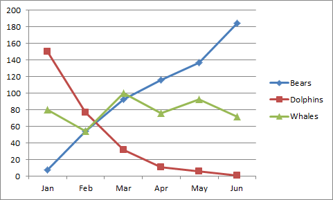
A simple chart in Excel can say more than a sheet full of numbers. As you'll see, creating charts is very easy.


Create a Line Chart:

To create a line chart, execute the following steps.
  • Select the range A1:D7
  • On the Insert tab, in the Charts group, choose Line, and select Line with Markers.


Result:


Change Chart Type

You can easily change to a different type of chart at any time.
  • Select the chart.
  • On the Insert tab, in the Charts group, choose Column, and select Clustered Column.


 Result:


Switch Row/Column

If you want the animals, displayed on the vertical axis, to be displayed on the horizontal axis instead, execute the following steps.
  • Select the chart. The Chart Tools contextual tab activates.
  • On the Design tab, click Switch Row/Column.


Result:


Chart Title

To add a chart title, execute the following steps.
  • Select the chart. The Chart Tools contextual tab activates.
  • On the Layout tab, click Chart Title, Above Chart.


Enter a title. For example, Population.

Result:


Legend Position

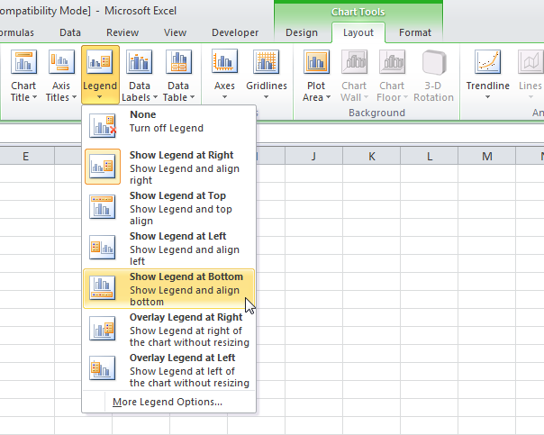
By default, the legend appears to the right of the chart. To move the legend to the bottom of the chart, execute the following steps.
  • Select the chart. The Chart Tools contextual tab activates.
  • On the Layout tab, click Legend, Show Legend at Bottom.


Result:


Data Labels

You can use data labels to focus your readers' attention on a single data series or data point.
  • Select the chart. The Chart Tools contextual tab activates.
  • Click an orange bar to select the Jun data series. Click again on an orange bar to select a single data point.
  • On the Layout tab, click Data Labels, Outside End.


 Result:


How to Disable Third-Party Cookies in Chrome and Firefox

$
0
0
If you are more tech savvy, you probably know that most of the websites that you visit store pieces of information right in your browser in the form of cookies. Generally speaking, cookies are a small piece of useful data that are used for tracking users’ activity in the website, to store stateful information like login sessions, shopping cart items, etc., and even to record and transmit the users’ browsing activity.

However, there are some third-party cookies that can track your activity without you even visiting the site. If you are really concerned about your privacy, here is how you can configure your Firefox and Chrome browser to disable third-party cookies.

In case you are wondering, first-party cookies are the cookies stored by the website you are visiting, and third-party cookies are nothing but the cookies whose domain or origin is different from the website you are visiting. Since the web browsers treat the first- and third-party cookies differently, it is easy to disable third-party cookies.

Disabling third-party cookies in Chrome is relatively easy and straightforward. First, click on the menu icon in the upper right corner and select the option “Settings” from the list.


The above action will open the Chrome settings tab. Here scroll down and click on the link “Show advanced settings.”


Now, click on the button “Content Settings” under the Privacy section. This action will open the Content settings window where you can manage a lot of things like the cookies, images, javascript, plugins, etc.


To disable the third-party cookies, select the check box “Block third-party cookies and site data” and click on the “Done” button appearing at the bottom right corner of the window to save the changes.


If there are any exceptions you want to place for the cookies, you can do so by clicking the button “Manage Exceptions” and adding the domain names accordingly.


From this point forward, Chrome displays a small icon in the Omnibar to visually indicate that the Chrome browser is blocking third-party cookies of the website you are visiting.


To disable third-party cookies in the Firefox browser, click on the menu icon and select the “Options” button to open the Firefox options window.


Once opened, navigate to the “Privacy” tab and select the option “Use custom settings for history” from the drop-down menu next to the wording “Firefox will” under the History section.


This action will display a few settings for the custom configurations. Select the option “Never” from the drop-down menu next to “Accept third-party cookies” and click on the “Ok” button to save the changes.


Just like in Chrome, if there are any exceptions you want to place, click on the “Exceptions” button and enter the domain names accordingly.


That’s all there is to do and it is that simple to disable third-party cookies in Firefox and Chrome.
That being said, if ever want to see what cookies are being used by a certain website in your Chrome browser. Simply right-click anywhere in the website, select the option “Inspect Element” and navigate to the “Resources” tab.

If you expand the Cookies tree, you will find all the cookies that are being used by the target website. If you are using Firefox, you can find the same under the Storage tab of Developer tools.


Hopefully that helps, and do comment below sharing your thoughts and experiences on blocking third-party cookies in Chrome and Firefox.

Samsung Unveils Pair of All-New Galaxy S6 Smartphone Models

$
0
0
Samsung's next-generation Galaxy S6 smartphones, which include giant leaps in style, design, components and features from earlier models, have finally arrived after months of rumors about how Samsung would fight off Apple's latest iPhone 6 devices.

The new Galaxy models, a standard Galaxy S6 and a much flashier and more sculptured Galaxy S6 Edge that features a bright display which wraps around both sides of the handset, were unveiled at Mobile World Congress 2015 in Barcelona, Spain, on March 1 during a special "Samsung Galaxy Unpacked" event a day before MWC opens officially.


Our first impressions, after seeing and handling the new Galaxy models up close at a special press preview briefing in New York City last week, is that these Galaxy smartphones appear to hit the mark when it comes to taking on the iPhone 6 and the iPhone 6 Plus around the world.

The improvements in the new S6 smartphones over the previous Galaxy S5 model are many, from a chassis made of aircraft-grade aluminum to a higher resolution 5.1-inch, quad HD Super AMOLED display (2,560-by-1,440 resolution for the S6 versus 1,920-by-1,080 for the S5) that has about 80 percent more pixels (577 pixels per inch) than the S5. Corning Gorilla Glass 4 is used on both the front display and rear panel of the phones.


Both new Galaxy S6 models also include Samsung's latest 14nm technology, 64- bit Exynos 7 processors, which have eight cores and use less power while providing higher performance than previous chips made with 20nm manufacturing processes. Full specifications and clock speeds for the new processors were not available at press time. Android 5.0 Lollipop is running on both devices.

Both the Galaxy S6 and the Galaxy S6 Edge also include new LPDDR4 flash RAM and nonexpandable UFS 2.0 flash storage that will be available in three capacities—32GB, 64GB and 128GB. The new S6 phones differ from the old S5 and previous versions by omitting micro SD memory card slots due to space constraints as the new devices are thinner.


Like the previous Galaxy S5, the new S6 models offer a 16-megapixel rear camera, but the latest versions add Smart Optical Image Stabilization (OIS), a 1.9 f lens and automatic real-time High Dynamic Range (HDR) processing for improved picture quality in low light and other conditions, according to Samsung. The 5MP front camera of the new Galaxies is also improved, with a 1.9 f lens, HDR, new white balance detection for improved images and other improvements that let users get better "selfies" when using the camera. Fast-tracking auto-focus is also now featured on the new S6 models.

Faster access to the cameras is also a benefit of the new S6 models thanks to a new "fast launch" feature that lets users capture a photograph as quickly as hitting the home button twice. The new Galaxy versions are always on camera standby mode, making faster use of the cameras possible at the spur of the moment. That's a far cry from the previous Galaxy S4 and S5 models.


Improved and faster charging, as well as wireless charging capabilities, is also built into the newest Galaxy S6 phones, with a fast charging mode that allows users to charge the battery to 50 percent in just 20 minute using a corded charger. The wireless charging system works with WPC or PMA wireless charging systems and can provide a 50 percent device charge in about 30 minutes.

The Galaxy S6 includes a 2,550mAh nonremovable battery, while the S6 Edge includes a 2,600mAh nonremovable battery. Audio quality is also improved over the earlier S5 model, with a speaker that provides sound that is up to 1.5 times louder than the previous-generation audio system in the older devices.

Both smartphone models support 4G Long Term Evolution (LTE) networks and will support future LTE networks as they are adopted by mobile carriers, according to Samsung.

The S6 measures 5.64 inches in length, 2.77 inches in width and 0.26 inches in thickness, while the S6 Edge measures 5.59 inches by 2.75 inches by 0.27 inches. The S6 weighs 4.86 ounces, while the S6 Edge weighs 4.65 ounces. 

The S6 will be available in Black Sapphire, Gold Platinum, Blue Topaz and White Pearl, while the S6 Edge will be available in Black Sapphire, White Pearl, Gold Platinum and Green Emerald. The faceplate and backplate colors are actually created through the use of thin colored foil-like materials that are positioned on the backside of the glass on the front and rear of each phone.

Both smartphones are equipped with Samsung KNOX and upgraded Find My Mobile security features that help users keep their work and personal content separate on their devices.

An integrated mobile payments system will be included in both phone versions in the future, but it is not ready at launch, according to Samsung. The system will include support for near-field communication (NFC) wireless payments and Magnetic Secure Transmission transactions as used in today's magnetic card swiping systems for credit cards, according to Samsung.


The user interfaces in the S6 models have also been improved and simplified as product designers worked closely with the user interface team to refine and streamline the phones, according to the company. Function menus were reduced by some 40 percent.

Hong Yeo, a Samsung senior product designer based in Seoul, told us that developing the S6 models, which had been code-named Project Zero, has been the most exciting design project his team has ever worked on.

"Everyone involved got together to really come out with a complete package," said Yeo. "We took a step back and listened to what customers were saying and what they wanted to communicate" about features they wanted to see. "We wanted to create a device with a lot of warmth and character. Both models represent a new design era for Samsung. It's something we've been working on for years."

Creating the thinner, more futuristic and more stylish S6 devices shaved 1mm in thickness and 2mm in width from the previous S5 smartphones, according to Yeo. "In our world, that's a massive difference."


The design team was free to use any materials for the phones, as long as the materials met the design standards for the project, he said. A key highlight of the project became the use of glass and metal in the new devices.

"It's not just any glass," said Yeo. "We added a reflective structure under the glass to capture light. It's an emotional form wrapped around a different product that the world d has never seen before."

The new S6 phones will ship in the second quarter of 2015. Pricing information has not yet been released. The previous Galaxy S5 version was released in April 2014.

The Web Will 'Just Work' With Windows 10 Browser

$
0
0
Project Spartan on Windows 10 PCs represents a break from Internet Explorer's checkered history, claims the company.

After a series of leaks, Microsoft finally took the lid off its next-generation Web browser, dubbed Project Spartan, when it officially unveiled the Windows 10 operating system to the public on Jan. 21 during a press event.


A new rendering engine, minimalist UI and features that allow users to "mark up the Web directly" came together for a fresh take on Windows-based Web browsing during a demonstration at the company's Redmond, Wash., headquarters. Now, Microsoft is detailing how Project Spartan is a departure from Internet Explorer (IE) and its past foibles.

In a lengthy blog post Feb. 26, Charles Morris, program manager lead for Project Spartan, admitted that as the IE version numbers crept upward, Microsoft "heard complaints about some sites being broken in IE—from family members, co-workers in other parts of Microsoft, or online discussions." Most of those sites fell outside of the company's Web compatibility target, namely the top 9,000 sites that account for an estimated 88 percent of the world's Web traffic.

As part of a new "interoperability-focused approach," his group decided to take a fork in the path laid out by previous versions of IE. "The break meant bringing up a new Web rendering engine, free from 20 years of Internet Explorer legacy, which has real-world interoperability with other modern browsers as its primary focus—and thus our rallying cry for Windows 10 became 'the Web just works,'" said Morris.

While Project Spartan's new rendering engine has its roots in IE's core HTML rendering component (MSHTML.dll), it "diverged very quickly," he said. "By making this split, we were able to keep the major subsystem investments made over the last several years, while allowing us to remove document modes and other legacy IE behaviors from the new engine."

IE isn't going away, however. "This new rendering engine was designed with Project Spartan in mind, but will also be available in Internet Explorer on Windows 10 for enterprises and other customers who require legacy extensibility support," Morris said.

Morris and his team are also leveraging analytic drawn from "trillions of URLs" and the company's Bing search technology to help inform the browser's development, suggesting that future builds of Project Spartan will be more closely aligned with the Web's evolution and his company's new cloud like approach to software updates.

"For users that upgrade to Windows 10, the engine will be evergreen, meaning that it will be kept current with Windows 10 as a service," he said, referencing the company's ambitious new OS strategy. A revamp of Microsoft's own practices is also helping to bring the team's vision to fruition, Morris revealed.

"In addition, we revised our internal engineering processes to prioritize real-world interoperability issues uncovered by our data analysis. With these processes in place, we set about fixing over 3000 interoperability bugs and adding over 40 new Web standards (to date) to make sure we deliver on our goals," he stated.

WatchGuard M500 Appliance Alleviates HTTPS Performance Woes

$
0
0
WatchGuard aims to alleviate the performance and security issues presented by the broad adoption of HTTPS with the M500 Unified Threat Management Appliance.

HTTPS has become the standard bearer for Web traffic, thanks to privacy concerns, highly publicized network breaches and increased public demand for heightened Web security.

While HTTPS does a great job of encrypting what used to be open Web traffic, the technology does have some significant implications for those looking to keep networks secure and protected from threats.

For example, many enterprises are leveraging unified threat management (UTM) appliances to prevent advanced persistent threats (APTs), viruses, data leakage and numerous other threats from compromising network security. However, HTTPS has the ability to hide traffic via encryption from those UTMs and, in turn, nullifies many of the security features of those devices.

That situation has forced appliance vendors to incorporate a mechanism that decrypts HTTPS traffic and examine the data payloads for problems. On the surface, that may sound like a solution to what should never have been a problem to begin with but, in fact, has created additional pain points for network managers.

Those pain points come in the form of throughput and latency, where a UTM now has to deal with encrypted traffic from hundreds or even thousands of users, straining application-specific ICs (ASICs) to the breaking point and severely degrading the performance of network connections. What’s more, the situation is only bound to get worse as more and more Websites adopt HTTPS and rely on the Secure Sockets Layer (SSL) protocol to keep data encrypted and secure from unauthorized decryption.

Simply put, encryption hampers a UTM’s ability to scan for viruses, spear-phishing attacks, APTs, SQL injection and data leakage, and reduces URL filtering capabilities.

WatchGuard Firebox M500 Tackles the Encryption Conundrum

WatchGuard Technologies, based in Seattle, has been a player in the enterprise security space for some 20 years and has developed numerous security solutions, appliances and devices to combat the ever-growing threats presented by connectivity to the world at large.

The company released the Firebox M500 at the end of November 2014 to address the ever-growing complexity that encryption has brought to enterprise security. While encryption has proven to be very beneficial for enterprise networks trying to protect privacy and prevent eavesdropping, it has also presented a dark side, where malware can be hidden within network traffic and only discovered at the endpoint, often too late.

The Firebox M500 pairs advanced processing power (in the form of multi-core Intel processors) with advanced heuristics to decrypt traffic and examine it for problems, without significantly impacting throughput or hampering latency. The M500 was designed from the outset to deal with SSL and open (clear) traffic using the same security technologies, bringing a cohesive approach to the multitude of security functions the device offers.

The Firebox M500 offers the following security services:

1. APT Blocker: Leverages a cloud-based service featuring a combination of sandboxing and full system emulation to detect and block APTs.

2. Application Control: Allows administrators to keep unproductive, inappropriate, and dangerous applications off limits from end users.

3. Intrusion Prevention Service (IPS): Offers in-line protection from malicious exploits, including buffer overflows, SQL injections and cross-site scripting attacks.

4. WebBlocker: Controls access via policies to sites that host objectionable material or pose network security risks.

5. Gateway AntiVirus (GAV): In-line scan of traffic on all major protocols to stop threats.

6. spamBlocker delivers continuous protection from unwanted and dangerous email.

7. Reputation-enabled defense: Uses cloud-based reputation lookup to promote safer Web surfing.

8. Data loss prevention: Inspects data in motion for corporate policy violations.

WatchGuard uses a subscription-based model that allows users to purchase features based on subscription and license terms. This model creates an opportunity for network administrators to pick and choose only the security services needed or roll out security services in a staggered fashion to ease deployment.

Installation and Setup

The Firebox M500 is housed in a 1u, red metal box that features six 1000/100/10 Ethernet ports, two USB ports, a Console port and a pair of optionally configurable small-form-factor pluggable ports. Under the hood resides an Intel Pentium G3420 processor and 8GB of RAM, as well as the company’s OS, FireWare 11.9.4.

The device uses a “man-in-the-middle” methodology to handle HTTPS traffic, allowing it to decrypt and encrypt traffic destined for endpoints on the network.

That man-in-the-middle approach ensures that all HTTPS (or SSL certificate-based traffic) must pass through the device and become subject to the security algorithms employed. This, in turn, creates an environment where DLP, AV, APT protection and other services can function without hindrance.

Initial deployment consists of little more than placing the M500 in an equipment rack and plugging in the appropriate cables. The device defaults to an open mode for outboard connections that allows all outbound traffic to enable administrators to quickly plug it in without much disruption.

On the other hand, inbound traffic will be blocked until policies are defined to handle that traffic. This can potentially cause some disruption to remote workers or external services until the device is configured.

A configuration wizard guides administrators through the steps to set up the basic security features. While the wizard does a decent job of preventing administrators from disrupting connectivity, there are settings that one must be keenly aware of to maintain efficient performance. The wizard also handles some of the more mundane housekeeping tasks, such as installing licenses, subscriptions, network configurations and so on.

To truly appreciate how the Firebox M500 works and to fully comprehend the complexity of the appliance, one must delve into policy creation and definition. Almost everything that the device does is driven by definable policies that require administrators to carefully consider what traffic should be allowed, should be examined and should be blocked.

Defining policies ranges from the simplistic to the very complex. For example, an administrator can define a policy that blocks Web traffic based on content in a few simple steps. All it takes is clicking on policy creation, selecting a set of predefined rules, applying those rules to users/ports/etc. and then clicking off on the types of content that are not allowed (such as botnets, keyloggers, malicious links, fraud, phishing, etc.).

Policy definition can also be hideously complex, such as with HTTPS proxy definition and the associated certificate management. Although the device steps you through much of the configuration, administrators will have to be keenly aware of exceptions that must be white-listed (depending on their business environment), privacy concerns and a plethora of other issues.

That said, complexity is inherent when it comes to controlling that type of traffic, and introducing simplicity would more than likely unintentionally create either false positives or limit full protection.

Naturally, performance is a key concern when dealing with encrypted traffic, and WatchGuard has addressed that concern by leveraging Intel processors, instead of creating custom ASICs to handle the traffic.

Independent performance testing by Miercom Labs shows that WatchGuard made the right choice by choosing CISC-based CPUs instead of taking a RISC approach. Miercom's testing report shows that the M500 is capable of 5,204M bps of throughput with Firewall services enabled.

For environments that will deploy multiple Firebox M500s across different locations, WatchGuard offers the WatchGuard System Manager, which uses templates for centralized management and offers the ability to distribute policies to multiple devices. That eliminates having to manage each M500 individually, beyond initially plugging in the device.

WatchGuard offers a deployment tool called RapidDeploy, which provides the ability to install a preconfigured/predefined image and associated policies on a freshly deployed device. Simply put, all anyone has to do is plug in the appliance and ensure there is connectivity, and an administrator located anywhere can set up the device in a matter of moments. That proves to be an excellent capability for those managing branch offices, remote workers, multiple sites or distributed enterprises.

The M500 starts at a MSRP of $6,190, (including one year of security services in a discounted bundle). APT services for a year add another $1,375, while a year's worth of DLP services adds another $665. The company offers significant discounts for multiyear subscriptions and also supports a vibrant reseller channel.

While the WatchGuard Firebox M500 may not be the easiest security appliance to deploy, it does offer all the features almost any medium enterprise would want. It also offers a solution to one of the most critical pain points faced by network administrators today—keeping systems secure, even when dealing with encrypted traffic.

How to Quickly Fix Boot Record Errors in Windows

$
0
0
If you have used Windows for a good amount of time, you may have come across boot record errors that prevent your Windows from booting up properly. The reasons for this error could be due to, but not limited to, corrupted or deleted boot files, removing Linux operating system from a dual-boot computer, mistakenly installing the older version of boot record, etc. 

The boot record errors are purely software errors and can be easily corrected using the Windows built-in tools and the installation media.
But the problem is that the Windows operating system doesn’t provide any sort of graphical user interface so as to fix the boot record problems with just a few clicks. So if you ever need to, here is how you can fix the Windows boot record errors by just entering a command or two into the Windows command prompt.

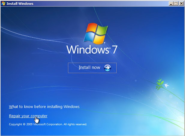
If you have a boot record problem, then you probably won’t be able to reach the Windows desktop and open command prompt from there. In this case, you have to insert the Windows OS installation media and boot from it. At the “Install Now” screen, click on the link “Repair your computer.”


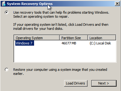
The above action will open the System Recovery Options window. Here select the operating system you want to recover and click on the “Next” button to continue.


Since we need the command prompt to work with, select the option “Command Prompt.”


Note: If you are using Windows 8 or 8.1, then press the F8 or “Shift + F8″ keys on your keyboard while booting, select the option “Troubleshoot -> Advanced Settings” and then again select Command Prompt from the list of the options to open the Command Prompt window.

Note: though I’m showing this on a Windows 7 computer, the procedure is one and the same for Vista and 8/8.1.

Once you are in the command prompt, we can start fixing the boot record error using the bootrec command. Most of the time boot record problems are a direct result of damaged or corrupted Master Boot Record. In those scenarios, simply use the below command to quickly fix the Master Boot Record.

bootrec /fixmbr
 
 
Once you execute the command, you will receive a confirmation message letting you know, and you can continue to log in to your Windows machine.

If you think your boot sector is either damaged or replaced by the other boot loaders, then use the below command to erase the existing one and create a new boot sector.

bootrec /fixboot
 
 
Besides corrupted boot records, boot record errors may also occur when the “Boot Configuration Data” has been damaged or corrupted. In those cases, you need to use the following command to rebuild the Boot Configuration Data. If the BCD is actually corrupted or damaged, Windows will display the identified Windows installations to rebuild the entire BCD.

bootrec /rebuildbcd
 
 
If you have installed multiple operating systems on your Windows machine then you might want to use the “ScanOS” argument. This parameter commands Windows to scan and add all the missing operating systems to the Boot Configuration Data. This enables the user to choose an operating system while booting.

bootrec /scanos
 
 
That’s all there is to do, and it is that simple to fix boot record errors in the Windows operating system.

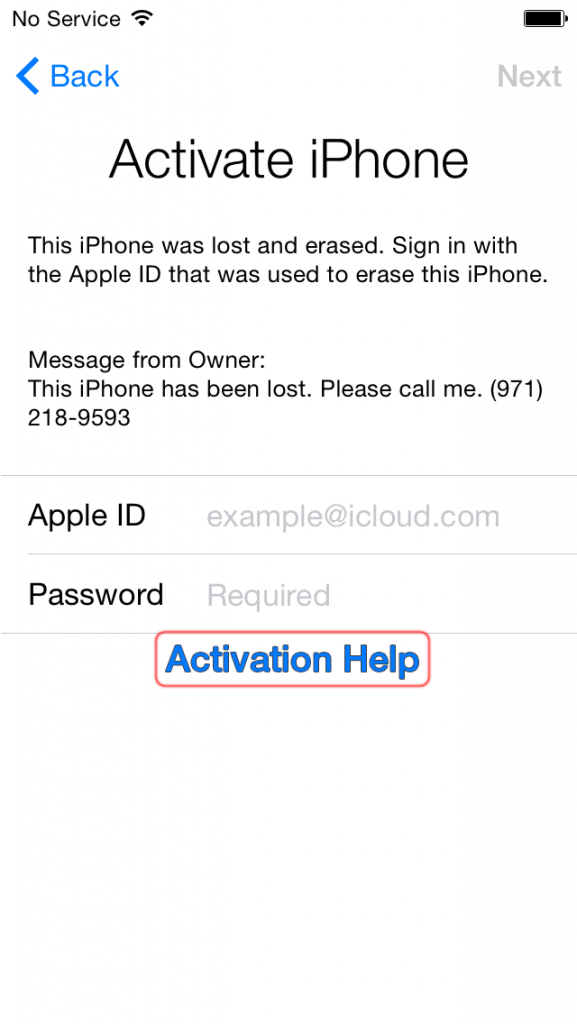
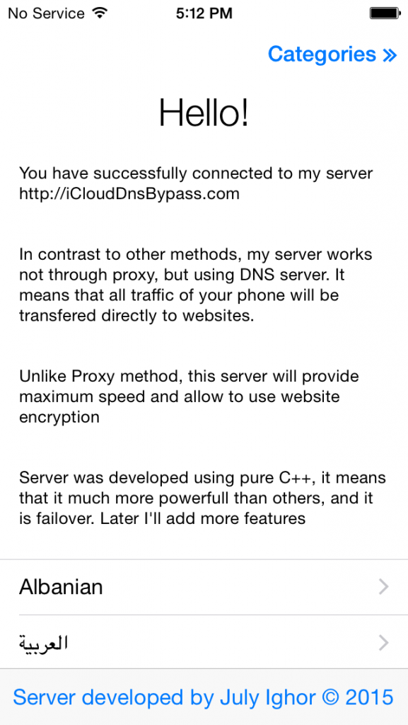
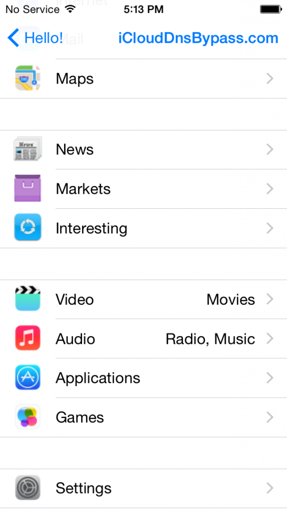
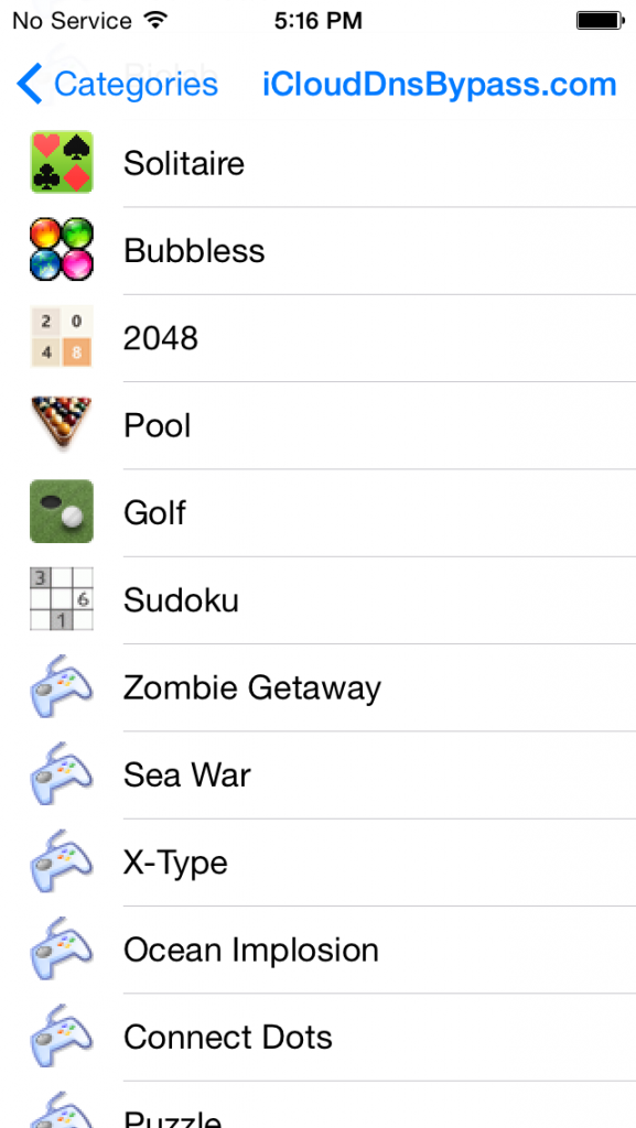
How to bypass iPhone, iPad, iPod with iCloud Bypass DNS Server

$
0
0

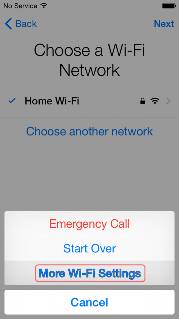
How to connect your iDevice to iCloud Bypass DNS Server

Follow the below step by step instruction in screenshots to use your iCloud locked device to watch videos, take pictures, listen music and much more, while you are waiting full bypass.


Hyper-V and Networking – Part 4: Link Aggregation and Teaming

$
0
0
In part 3, I showed you a diagram of a couple of switches that were connected together using a single port. I mentioned then that I would likely use link aggregation to connect those switches in a production environment. Windows Server introduced the ability to team adapters natively starting with the 2012 version. Hyper-V can benefit from this ability.

      To save you from needing to click back to part 2, here is the visualization again:


      Port 19 is empty on each of these switches. That’s not a good use of our resources. But, we can’t just go blindly plugging in a wire between them, either. Even if we configure ports 19 just like we have ports 20 configured, it still won’t work. In fact, either of these approaches will fail with fairly catastrophic effects. That’s because we’ll have created a loop
      Imagine that we have configured ports 19 and 20 on each switch identically and wired them together. Then, switch port 1 on switch 1 sends out a broadcast frame. Switch 1 will know that it needs to deliver that frame to every port that’s a member of VLAN 10. So, it will go to ports 2-6 and, because they are trunk ports with a native VLAN of 10, it will also deliver it to 19 and 20. Ports 19 and 20 will carry the packet over to switch 2. When it comes out on port 19, it will try to deliver it to ports 1-6 and 20. When it comes out on port 20, it will try to deliver it to ports 1-6 and port 19. So, the frame will go back to ports 19 and 20 on switch 1, where it will repeat the process. Because Ethernet doesn’t have a time to live like TCP/IP does (at least, as far as I know, it doesn’t), this process will repeat infinitely. That’s a loop.

      Most switches can identify a loop long before any frames get caught up. The way Cisco switches will handle it is by cutting off the offending loop ports. So, if it’s the only connection that switch has with the outside world, all its endpoints will effectively go out. I’ve never put any other manufacturer into a loop, so I’m not sure how the various other vendors will deal with it. No matter what, you can’t just connect switches to each other using multiple cables without some configuration work.

      Port Channels and Link Aggregation

      The answer to the above problem is found in Port Channels or Link Aggregation. A port channel is Cisco’s version. Everyone else calls it link aggregation. Cisco does have some proprietary technology wrapped up in theirs, but it’s not necessary to understand that for this discussion. So, to make the above problem go away, we would assign ports 19 and 20 on the Cisco switch into a port channel. On any other hardware vendor, we would assign them to a link aggregation group (LAG). Once that’s done, the port channel or LAG is then configured just like a single port would be, as in trunk/(un)tagged or access/PVID. What’s really important to understand here is that the MAC addresses that the switch assigned to the individual ports are gone. The MAC address now belongs to the port channel/LAG. MAC addresses that it knows about on the connecting switch are delivered to the port channel, not to a switch port.

      LAG Modes

      It’s been quite a while since I worked on a Cisco environment, but as I recall, a port channel is just a port channel. You don’t need to do a lot of configuration once it’s set up. For other vendors, you have to set up the mode. We’re going to see these modes again with the Windows NIC team, so we’ll get acquainted with that first.

      NIC Teaming

      Now we look at how this translates into the Windows and Hyper-V environment. For a number of years, we’ve been using NIC teaming in our data centers to provide a measure of redundancy for servers. This uses multiple connections as well, but the most common types don’t include the same sort of cooperation between server and switch that you saw above between switches. Part of it is that a normal server doesn’t usually host multiple endpoints the way a switch does, so it doesn’t really need a trunk mode.

      A server is typically not concerned with VLANs. So, usually a teamed interface on a server isn’t maintaining two active connections. Instead, it has its MAC address registered on one of the two connected switch ports and the other is just waiting in reserve. Remember that it can’t actually be any other way, because a MAC address can only appear on a single port. So, even though a lot of people thought that they were getting aggregated bandwidth, they really weren’t. But, the nice thing about this configuration is that it doesn’t need any special configuration on the switch, except perhaps if there is a security restriction that prevents migration of MAC addresses.

      New, starting in Windows/Hyper-V Server 2012, is NIC teaming built right into the operating system. Before this, all teaming schemes were handled by manufacturers’ drivers. There are three teaming modes available.

      Switch Independent

      This is the same mode as the traditional teaming mode. The switch doesn’t need to participate. Ordinarily, the Hyper-V switch will register all of its virtual adapters’ MAC addresses on a single port, so all inbound traffic comes through a single physical link. We’ll discuss the exceptions in another post. Outbound traffic can be sent using any of the physical links.

      The great benefit of this method is that it can work with just about any switch, so small businesses don’t need to make special investments in particular hardware. You can even use it to connect to multiple switches simultaneously for redundancy. The downside, of course, is that all incoming traffic is bound to a single adapter.

      Static

      The Hyper-V virtual switch and many physical switches can operate in this mode. The common standard is 802.3ad, but not all implementations are equal. In this method, each member is grouped into a single unit as explained in the Port Channels and Link Aggregation section above. Both switches (whether physical or virtual) much have their matching members configured into a static mode.

      MAC addresses on all sides are registered on the overall aggregated group, not on any individual port. This allows incoming and outgoing traffic to use any of the available physical links. The drawbacks are that the switches all have to support this and you lose the ability to split connections across physical switches (with some exceptions, as we’ll talk about later).

      If a connection experiences troubles but isn’t down, then the static switch will experience problems that might be difficult to troubleshoot. For instance, if you create a static team on 4 physical adapters in your Hyper-V host but only three of the switch’s ports are configured in a static trunk, then the Hyper-V system will still attempt to use all four.

      LACP

      LACP stands for “Link Aggregation Control Protocol”. This is defined in the 802.1ax standard, which supersedes 802.3ad. Unfortunately, there is a common myth that gives the impression that LACP provides special bandwidth consolidation capabilities over static aggregation. This is not true. An LACP group is functionally like a static group.

      The difference is that connected switches communicate using LACPDU packets to detect problems in the line. So, if the example setup at the end of the Static teaming section used LACP instead of Static, the switches would detect that one side was configured using only 3 of the 4 connected ports and would not attempt to use the 4th link. Other than that, LACP works just like static. The physical switch needs to be setup for it, as does the team in Windows/Hyper-V.

      Bandwidth Usage in Aggregated Links

      Bandwidth usage in aggregated links is a major confusion point. Unfortunately, it’s not a simple matter of all physical links being simply combined into one bigger one. It’s more likely that load-balancing will occur than bandwidth aggregation.

      In most cases, the sending switch/team controls traffic flow. Specific load-balancing algorithms will be covered in another post. However it chooses to perform it, the sending system will transmit on a specific link. But, any given communication will almost exclusively use only one physical link. This is mostly because it helps ensure that the frames that make up a particular conversation arrive in order.

      If they were broken up and sent down separate pipes, contention and buffering would dramatically increase the probability that they would be scrambled before reaching their destination. TCP and a few other protocols have built-in ways to correct this, but this is a computationally expensive operation that usually doesn’t outweigh the restrictions of simply using a single physical link.
      Another reason for the single-link restriction is simple practicality.

      Moving a transmission through multiple ports from Switch A to Switch B is fairly trivial. From Switch B to Switch C, it becomes less likely that enough links will be available. The longer the communications chain, the more likely a transmission won’t have the same bandwidth available as the initial hop. Also, the final endpoint is most likely on a single adapter. The available methods to deal with this are expensive and create a drag on network resources.

      The implications of all this aren’t exactly clear. A quick explanation is that no matter what teaming mode you pick, when you run a network performance test across your team, the result is going to show the maximum speed of a single team member. But, if you run two such tests simultaneously, it might use two of the links. What I normally see is people trying to use a file copy to test bandwidth aggregation. Aside from the fact that file copy is a horrible way to test anything other than permissions, it’s not going to show anything more than the speed of a single physical link.

      The exception to the sender-controlling rule is the switch-independent teaming mode. Inbound traffic is locked to a single physical adapter as all MAC addresses are registered in a single location. It can still load-balance outbound traffic across all ports. If used with the Hyper-V port load-balancing algorithm, then the MAC addresses for virtual adapters will be evenly distributed across available physical adapters. Each virtual adapter can still only receive at the maximum speed of a single port, though.

      Stacking Switches

      Some switches have the power to “stack”. What this means is that individual physical switches can be combined into a single logical unit. Then, they share a configuration and operate like a single unit. The purpose is for redundancy. If one of the switch(es) fails, the other(s) will continue to operate. What this means is that you can split a static or LACP inter-switch connection, including to a Hyper-V switch, across multiple physical switch units. It’s like having all the power of the switch independent mode with none of the drawbacks.

      One concern with stacked switches is the interconnect between them. Some use a special interlink cable that provides very high data transfer speeds. With those, the only bad thing about the stack is the monetary cost. Cheaper stacking switches often just use regular Ethernet or 1gb or 2gb fiber. This could lead to bandwidth contention between the stack members. Since most networks use only a fraction of their available bandwidth at any given time, this may not be an issue. For heavily loaded core switches, a superior stacking method is definitely recommended.

      Aggregation Summary

      Without some understanding of load-balancing algorithms, it’s hard to get the complete picture here. These are the biggest things to understand:
      • The switch independent mode is the closest to the original mode of network adapter teaming that has been in common use for years. It requires that all inbound traffic flow to a single adapter. You cannot choose this adapter. If combined with the Hyper-V switch port load-balancing algorithm, virtual switch ports are distributed evenly across the available adapters and each will use only its assigned port for inbound traffic.
      • Static and LACP modes are common to the Windows/Hyper-V Server NIC team and most smart switches.
      • Not all static and LACP implementations are created equally. You may encounter problems connecting to some switches.
      • LACP doesn’t have any capabilities for bandwidth aggregation that the static method does not have.
      • Bandwidth aggregation occurs by balancing different communications streams across available links, not by using all possible paths for each stream.

      What’s Next

      While it might seem logical that the next post would be about the load-balancing algorithms, that’s actually a little more advanced than where I’m ready for this series to proceed. Bandwidth aggregation using static and LACP modes is a fairly basic concept in terms of switching. I’d like to continue with the basics of traffic flow by talking about DNS and protocol bindings.

      How to Root Any Samsung Galaxy S4 in One Click

      $
      0
      0

      Method # 1


      Step 1: Download & Install TowelRoot

      The process couldn't be easier—start by making sure you have installation from "Unknown sources" enabled, then just grab the TowelRoot apk from here and install.


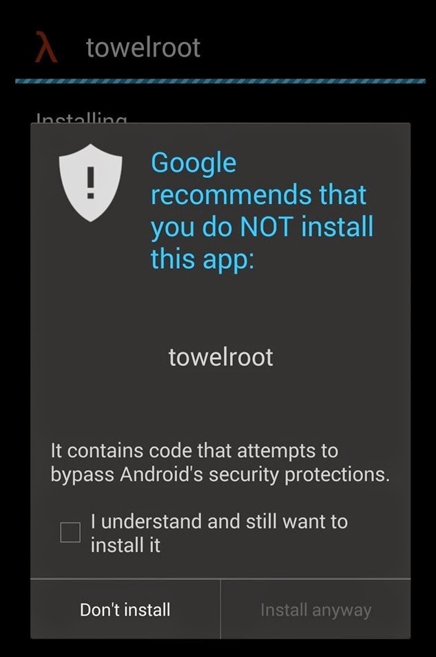
      We're rooting using a pretty genius method. It basically exploits the kernel, which freezes Android, and while the OS is sitting there panicking, it asks for root privileges and Android gives them to it. Then, it copies over the necessary root files and reboots the phone. But because of the way this exploit functions, you'll see a nice scary warning when installing TowelRoot—check that you understand the risks, then hit Install anyway.

      Step 2: Run TowelRoot

      Now hit the make it ra1n button, and let the app do its thing. It'll automatically reboot your device, and then you'll be rooted!


      Yes, it really is that easy. Really.


      Step 3: Install SuperSU

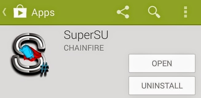
      While TowelRoot will root your device, it will not install a root manager, which is critical for keeping malicious apps from gaining root access. Far and away the best root manager is SuperSU from developer Chainfire. Head to the Play Store to grab the app directly.


      Install it and run. You can skip the part where the app asks if you'd like it to remove KNOX, but to each their own. Either way, you're rooted and ready to roll. And it couldn't have been easier.

      Method # 2


      Now root your GALAXY S4 by following the guide below!

      Preparations :

      • Free download Kingo Android Root and install it on your computer.
      • Make sure your device is powered ON.
      • At least 50% battery level.
      • USB Cable (the original one recommended).
      • Enable USB Debugging on your device.


      Step 1: Launch Android ROOT and connect GALAXY S4 to computer.

      After downloading and installing, double-click the desktop icon of Android ROOT to launch the software. The interface will be shown as below. Then follow the instructions and connect your GALAXY S4 to computer via USB cable. It is highly recommended that you use the original cable and plug it into the back of your computer to make sure the connection is stable, which is critical to the whole rooting process.


      Step 2: Waiting for automatic driver installation to complete.

      You may need to wait a little longer if this is the first time you connect your device to computer. Driver software installation should be done automatically. But sometimes, it often goes wrong. Do not be frustrated and try several times. If it still fails, manually download and install the correspond driver on the official website of Samsung. Contact us at any time if necessary.


      Step 3: Enable USB debugging mode on your GALAXY S4.

      If you have already done this, skip this step and move on. If not, please follow the instructions as shown on the software interface according to your Android version.


      Step 4: Read the notifications carefully before proceeding.

      Rooting is a modification of the original operating system and it may lead to certain consequences. Before you jump into any operation, you should know the risks and make a wise decision. So if you are not sure what ROOT means, consult GOOGLE, refer to detailed information or contact us.


      Step 5: Click ROOT to start the process when you are ready.

      It will take 3 to 5 minutes to complete the process. Once you started, do not move, touch, unplug USB cable, or perform any operation on your device anyhow!


      Step 6: ROOT Succeeded! Click Finish and wait for reboot.

      Your device is now successfully rooted. And you need to click Finish to reboot it in order to make it more stable. Still, do not touch, move or unplug it until it reboots. Check your device and find out SuperSU icon, which is the mark of a successful ROOT.


      One thing about Kingo ROOT that worth your attention is that there is the REMOVE ROOT function built in, which means you may use it to remove ROOT from your GALAXY S4 with just one-click as well, clean and simple.

      How To Activate WhatsApp Calling For Android

      $
      0
      0
      Get the latest WhatsApp for Android
      WhatsApp Calling, the new invitation-only feature of WhatsApp that adds free phone call capabilities to the app that was previously only capable of messaging, has officially been launched.

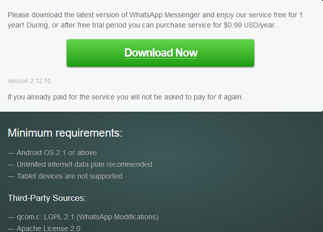
      The feature can be accessed by users running WhatsApp version 2.12.10 or  2.11.528 from the Google Play Store, or version 2.11.531 if downloaded directly from the official website of WhatsApp.


      The rollout of the feature was first tested by WhatsApp in India early last month, with the feature then already tagged as an invitation-only. Users that wish to test the WhatsApp call feature first had to receive a call from another user to activate the feature, even if the user already had the latest version of WhatsApp installed.

      With the official launch of WhatsApp Calling, the process of triggering the feature to be activated is to receive a call from another WhatsApp user that already has the feature unlocked, showing no change to the process that was implemented for WhatsApp Calling's testing. However, if the user being called up does not have the latest version of WhatsApp installed, a notification will be sent to request the user to update the app before the call is made.

      According to Android news website Android Police, after a user receives a call from another WhatsApp user with the WhatsApp Calling feature already activated, the user interface for the app changes, either instantly or after the user closes and then re-opens WhatsApp. The new user interface displays three tabs, labeled as calls, chats and contacts.

      The call feature has been integrated well into WhatsApp, with the tab for WhatsApp Calling showing all incoming, outgoing and missed calls with their exact times. Calls that are ongoing are placed in the app's notification panel until the call is ended, and calls that are missed leave notifications that can later be checked by the user. While in a call, users can choose to mute their microphones or to turn on the loudspeaker.

      Accessing the call feature can be done through the messages with any of the user's contact, as a call button will appear as one of the options in the action bar for that user beside the attach option and the menu.

      Users that tap on the avatar of a contact will also be shown a profile image of the user that is bigger in size, with options of either sending them a message or calling them displayed, along with viewing their information.

      The call button for contacts now leads by default to a WhatApp call, as opposed to a smartphone call in the past.

      How to enable WhatsApp voice calls (with root)

      In case none of this is still working for you, there is another way for rooted users to force the feature onto their phones, but it is a bit of a pain, as you’ll need to be connected to your PC and open a terminal every time you want to WhatsApp call someone (until it is enabled permanently for you).
      Just open a terminal emulator and enter the following command:

      su -c am start -n com.whatsapp/com.whatsapp.HomeActivity

      Have you got the feature yet? Will you now turn to WhatsApp as your default dialer?

      Oracle Database 12c Release 1 (12.1) RAC On Windows 2012 Step By Step Installation

      $
      0
      0
      This article describes the installation of Oracle Database 12c Release 1 (12.1) RAC on Windows 2012 Server Standard Edition using virtual environment with no additional shared disk devices.


      • Introduction
      • Download Software
      • VirtualBox Installation
      • Virtual Machine Setup
      • Guest Operating System Installation
      • Oracle Installation Prerequisites
      • Create Shared Disks
      • Clone the Virtual Machine
      • Install the Grid Infrastructure
      • Install the Database Software and Create a Database
      • Check the Status of the RAC


      Introduction

      One of the biggest obstacles preventing people from setting up test RAC environments is the requirement for shared storage. In a production environment, shared storage is often provided by a SAN or high-end NAS device, but both of these options are very expensive when all you want to do is get some experience installing and using RAC. A cheaper alternative is to use a FireWire disk enclosure to allow two machines to access the same disk(s), but that still costs money and requires two servers. A third option is to use virtualization to fake the shared storage.

      Using VirtualBox you can run multiple Virtual Machines (VMs) on a single server, allowing you to run both RAC nodes on a single machine. In additon, it allows you to set up shared virtual disks, overcoming the obstacle of expensive shared storage.


      Before you launch into this installation, here are a few things to consider.
      • The finished system includes the host operating system, two guest operating systems, two sets of Oracle Grid Infrastructure (Clusterware + ASM) and two Database instances all on a single server. As you can imagine, this requires a significant amount of disk space, CPU and memory.
      • Following on from the last point, the VMs will each need at least 3G of RAM, preferably 4G if you don't want the VMs to swap like crazy. Don't assume you will be able to run this on a small PC or laptop. You won't.
      • This procedure provides a bare bones installation to get the RAC working. There is no redundancy in the Grid Infrastructure installation or the ASM installation. To add this, simply create double the amount of shared disks and select the "Normal" redundancy option when it is offered. Of course, this will take more disk space.
      • During the virtual disk creation, I always choose not to preallocate the disk space. This makes virtual disk access slower during the installation, but saves on wasted disk space. The shared disks must have their space preallocated.
      • This is not, and should not be considered, a production-ready system. It's simply to allow you to get used to installing and using RAC.
      • The Single Client Access Name (SCAN) should be defined in the DNS or GNS and round-robin between one of 3 addresses, which are on the same subnet as the public and virtual IPs. Prior to 11.2.0.2 it could be defined as a single IP address in the "/etc/hosts" file, which is wrong and will cause the cluster verification to fail, but it allowed you to complete the install without the presence of a DNS. This does not seem to work for 11.2.0.2 onward.
      • The virtual machines can be limited to 2Gig of swap, which causes a prerequisite check failure, but doesn't prevent the installation working. If you want to avoid this, define 3+Gig of swap.
      • This article uses the 64-bit versions of Windows and Oracle 11g Release 2.
      • In this article I am using a Oracle Linux as my host OS.


      Download Software

      Download the following software.


      VirtualBox Installation

      First, install the VirtualBox software. On RHEL and its clones you do this with the following command as the root user.
      # rpm -Uvh VirtualBox-4.2-4.2.16_86992_el6-1.x86_64.rpm
      The package name will vary depending on the host distribution you are using. Once complete, VirtualBox is started from the menu.


      Virtual Machine Setup

      Now we must define the two virtual RAC nodes. We can save time by defining one VM, then cloning it when it is installed.

      Start VirtualBox and click the "New" button on the toolbar. Enter the name "w2012-121-rac1", OS "Microsoft Windows" and Version "Windows 2012 (64 bit)", then click the "Next" button.

      BlackBerry launches encrypted enterprise messaging service BBMProtected for iOS

      $
      0
      0

      BlackBerry today announced that it is bringing BBM Protected — its enterprise-grade encrypted messaging service — to BBM for iOS.

      The keys to encrypt messages in BBM Protected will be generated on the iPhone device itself. This prevents any “‘man in the middle’ hacker attacks, providing greater security than competing encryption schemes, and earning BBM Protected FIPS 140-2 validation by the U.S. Department of Defense.”


      The feature can be easily deployed in enterprises that already use BBM for communication, and does not require any additional setup or OS upgrade on their side.

      BBM Protected users can start a chat with other BBM Protected users in their organisation as well as outside of it. In case the recipient (or sender) does not use BBM Protected, the other party in the conversation can still initiate an encrypted and trusted chat environment.

      BBM Protected is a paid service, though BlackBerry is offering a free 30-day trial to enterprises. It is also available for Android and BlackBerry OS 10 running devices.

      Hyper-V and Networking – Part 6: Ports, Sockets and Applications

      $
      0
      0
      In many ways, this particular post won’t have a great deal to do with Hyper-V itself. It will earn its place in this series by helping to clear up a common confusion point I see being posted on various Hyper-V help forums. People have problems moving traffic to or from virtual machines, and, unfortunately, spend a lot of time working on the virtual switch and the management operating system.

      Ports

      From the previous parts of this series, you should now have a basic understanding of how traffic moves between computers using the TCP/IP protocol suite. Rarely is traffic simply between two computers, though. Usually, specific applications are communicating. Web server and web browser, SQL server and business client, control system and telnet client. All of these applications could be running on any given system simultaneously (you should probably separate the servers, though). Because so many network-enabled applications could be co-existing, it’s not enough for a computer to just fire packets at a target IP address. More is necessary in order for those packets to find their way to the destination application. The answer to this problem is the port.

      Ports are used with the TCP and UDP protocols and are really nothing more than a numerical identifier that’s in the header of the packet. A server (piece of software) will tell the system that it wants to process all incoming TCP and/or UDP traffic tagged with that specific port number. This is known as listening. Of course, most communication is two-way. So, in addition to the destination port, the packet also contains a source port. When the server responds to the client, it will use that destination port.

      Ports are allotted 2 bytes in the packet, giving them a range of 0000 through FFFF in hexadecimal or 0-65535 in decimal. I wasn’t around for the discussions on this, but 65535 is the maximum value for an unsigned 16-bit integer, and 16 bits was the largest integer size that was universally common among processors during the rise of IPv4, so I suspect a correlation.

      According to standards, this 2-byte range is broken into three groups: system ports (commonly referred to as well-known ports) are in the range of 0-1023, user ports are from 1024 to 49151, and dynamic ports start at 49152 and run the series out at 65535. The first two are controlled by the Internet Engineering Task Force (IETF) and I personally feel they are somewhat misleadingly named. The IETF retains rigid control over the so-called system ports, but they are not reserved for operating systems or anything like that. They are for common services, such as web and telnet.

      Anyone can apply to the Internet Assigned Numbers Authority (IANA) to have one of the user ports assigned to his/her application or service, such as 5900 for “remote frame buffer”, which is the protocol used by VNC. The final range is open for pretty much anyone to use for anything.

      You’ll notice that the previous paragraph opened with the qualifier of “standards”. That’s because there’s really no way to enforce what happens on any given port. Port 80 is “well-known” to be the port for web servers to use, but it’s trivially simple to code any application to listen on that port or any other.

      I promise you some pictures and further explanation, but I think this is a great place to segue into a discussion of sockets.

      Sockets

      Ports are nice, but they can only get you so far. An application can register a port, but that just facilitates communications. A port alone does not a communications channel make. This is where the socket comes in.

      Sockets are a simple thing. They are the point of contact for a network-enabled application on a computer. Sockets have their own addresses, which are just a combination of the IP address of the host and a specific port. They are what makes TCP and UDP communications possible. In order for proper communication to occur, a TCP or UDP packet requires a destination socket address. Let’s examine the flow:

      Problem: A user wants to retrieve a web page from the Techsupportpk web site. He types http://www.techsupportpk.com into the web browser and presses the Go button.
      1. From the above, the web client knows two things: the user wants the default page from www.techsupportpk.com on the http protocol.
      2. The first thing it does is resolve the hostname www.techsupportpk.com to an IP address using DNS: 64.91.230.229
      3. Because the user specified http, it knows to use port 80.
      4. Therefore, the destination socket is 64.91.230.229:80.
      The destination portion of the packet is now ready for transmission. But, that’s not quite enough. Since the user is asking the web server to deliver a web page, the target server needs to know where to send that page data. The mechanics to handle this are built right into TCP and UDP. The source system first inserts its own IP address in the source IP portion of the packet. Next, it produces a number from the range of dynamic ports (usually at random), and inserts that as well. That’s the source socket. The packet that it sends out looks like this:

      As you’ll recall from previous discussions, traffic doesn’t really move in a message-response fashion. It’s all a send operation. So, what happens is that the destination application is provided with the source socket information. Remember how I said that the OSI model is just a model and that practice is always different? This is one of those places. The complete layer 3 packet doesn’t necessarily survive all the way into layer 7, but the application layer is aware of both the source IP address and the source port. So, when it processes the request and wants to send back a “reply”, it simply reverses the way the socket information was placed in the packet that it received. Outside the contents of the data portion, the packets going back to the source will be the inverse of those coming in:


      What you’re seeing above is the motion of traffic between two sockets. A server application will always have a socket prepared for incoming traffic. This is called listening. A listening socket doesn’t care where the packet came from. It only cares that it was sent to the socket’s address. The socket belonging to the originating client application, however, will (or should) only accept traffic on its socket that is an inverse match for the request that it made. By maintaining a hash table of the destination socket addresses and dynamic source ports that it has made requests on, the application can easily manage multiple connections to multiple destinations. By maintaining a hash table of the sockets, a host can easily manage the traffic for multiple server and/or client applications. 

      Network Address Translation

      There is one inaccuracy in the sample image illustrating the communications chain. The source IP that I used is from a private range. These ranges (10.0.0.0/8, 169.254.0.0/16, 172.16.0.0/12, and 192.168.0.0/16) are not allowed on the open Internet. Any packet with one of these addresses as a source or destination will be dropped by the first Internet router that processes it.

      The purpose of these private ranges is to address IP address starvation. Within IPv4, there aren’t nearly enough addresses for every device worldwide to have its own. But, any organization is free to use private ranges, as its guaranteed that duplicate addresses in these spaces cannot collide across the Internet. Organizations then link up to the rest of the Internet using just one or only a few public IPs.

      In the above diagram, all six of those companies, all of various sizes, connect to the Internet consuming only a single public IP address apiece. Their internal networks are much larger, and some even use the same addressing scheme as other corporations. Network address translation (NAT) is the technology that facilitates this, and it’s very easy to understand. 
      When a web browser sends a request to a web site, it can remember all the socket information that was used in the request. When a packet comes in with the socket information reversed, that’s how it knows that it has received a response to that particular request.


      This is the same concept that NAT operates upon. The web browser sends its packets out, where they eventually reach the router that divides the private network from the public Internet. Unlike a standard router, a NAT router is going to make modifications to the layer 3, and possibly even the layer 4, portion of the packet.
      Just like the requesting application builds a hash table out of the source port and target sockets in order to match incoming packets with requests, the NAT router keeps its own table comparing source sockets, destination sockets, and its own replacement source sockets. The router won’t always need to replace the source port, but it often will in order to prevent collisions from multiple source machines attempting to connect to the same target IP using the same source port. When a responding packet is received that is an inverse match for an item in its table, the NAT router performs the same replacement in reverse so that the sending application can also correctly identify incoming packets. 

      Application to Hyper-V

      Hyper-V is largely unconcerned with most of what we’ve talked about in this article. The significance is that some people seem to become agitated when they learn that the Hyper-V virtual switch is a switch, not a router. It can, and does, perform the MAC address replacements that we saw in part 3, but it doesn’t track source and destination ports the same way. In fact, barring the use of an extension, the only way Hyper-V becomes at all concerned with ports is if you establish ACLs. These ACLs allow you to selectively allow or deny communications to/from specific ports, among other criteria.

      While the virtual switch is probably Hyper-V’s biggest network component, that’s certainly not all it does. Many of its other functions are facilitated by SMB, which uses the well-known port of 445. The management operating system also needs network communications to function, just like any other Windows installation. If you poke around in the default firewall rules, you’ll find a number of important services, such as those belonging to remote access applications.

      What’s Next

      In the next installment in this series, I’m going to refresh an older post about bindings in Hyper-V.

      Google adds ‘On-body detection’ Smart Lock mode to Android Lollipopdevices

      $
      0
      0

      Google seems to be rolling out a new ‘Smart Lock’ feature for Android devices running Lollipop — On-body detection. This new feature will only lock your device when it is sitting on a table or in your pocket.

      The feature will make use of the accelerometer on your Android device to detect any movement. In case it does not detect any movement, it will automatically lock your device. But if you are holding the device in your hand and it is already unlocked, On-body will keep it unlocked.


      In case you hand over your device to someone while it is unlocked, On-body will keep it unlocked. The feature cannot determine who is holding the device, it only knows that someone is holding it and thus keeps it unlocked.

      Google is rolling out the feature only to selected users for now, but it is likely that a wider rollout will start within the next few weeks. For now, the feature has only shown up on Nexus devices, but it is likely that Google will roll it out to other Android devices running Lollipop as well.


      iPhone’s Passcode Bypassed Using Software-Based Bruteforce Tool

      $
      0
      0
      Last week, a blogger reported on a $300 device called the IP Box, which was allowing repair shops and hackers to bypass passcodes and gain access to locked iOS devices. But it turns out that expensive hardware isn’t required; TransLock, a new utility for Mac, can do the same job over USB.

      MDSec’s video proved that the IP Box was able to bypass an iOS passcode using brute-force and maintain the data on an iPhone, iPad, or iPod touch even when the device is set to erase itself automatically when an incorrect passcode has been entered ten times.


      But developer Majd Alfhaily, creator of the Freemanrepo that hosts many popular jailbreak tweaks, has been able to replicate a similar brute-force attack using only an application running on a Mac.

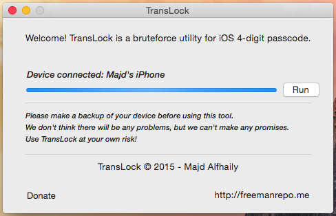
      “I tried to replicate the attack while covering the entire process without using hardware hacks,” Alfhaily explains in a post on his blog. He built an app called TransLock, which tries every possible 4-digit passcode starting from 0000 and ending at 9999.

      TransLock isn’t just cheaper than the IP Box, but it’s faster, too. It takes just 5 seconds for the app to try each passcode, which means it would take 14 hours to try every single combination. The IP Box takes 40 seconds to try each one, which means it could take up to 110 hours.

      Alfhaily explains how the whole things works on his blog, so if you’re into code, you can get more details there. But for the rest of us, the demonstration video below shows how TransLock works.

      Despite the security concerns, Alfhaily has no plans to keep TransLock to himself. “I’m working on a Mac utility that’ll automate the entire process and send the library to the device over a USB connection,” he writes. “I have plans to release it in the near future.”

      Unlike IP Box, however, TransLock will only work on a jailbroken iOS device, so those that haven’t been hacked are safe. In addition, it works with 4-digit passcodes only, so you can use a more complex password if you’re really worried about the vulnerability.

      It’s certainly concerning that iOS can be vulnerable to hacks like this, but this is exactly why Apple is against jailbreaking. But as for the IP Box, the Cupertino company will surely have to find a fix for that before the device becomes more popular.

      Adaptive SQL Plan Management (SPM) in Oracle Database 12c Release 1 (12.1)

      $
      0
      0
      SQL Plan Management was introduced in Oracle 11g to provide a "conservative plan selection strategy" for the optimizer. The basic concepts have not changed in Oracle 12c, but there have been some changes to the process of evolving SQL plan baselines. As with previous releases, auto-capture of SQL plan baselines is disabled by default, but evolution of existing baselines is now automated. In addition, manual evolution of sql plan baselines has been altered to a task-based approach. This article focuses on the changes in 12c.


      • SYS_AUTO_SPM_EVOLVE_TASK
      • Manually Evolving SQL Plan Baselines

      SYS_AUTO_SPM_EVOLVE_TASK

      In Oracle database 12c the evolution of existing baselines is automated as an advisor task called SYS_AUTO_SPM_EVOLVE_TASK, triggered by the existing "sql tuning advisor" client under the automated database maintenance tasks.
      CONN sys@pdb1 AS SYSDBA

      COLUMN client_name FORMAT A35
      COLUMN task_name FORMAT a30

      SELECT client_name, task_name
      FROM dba_autotask_task;

      CLIENT_NAME TASK_NAME
      ----------------------------------- ------------------------------
      auto optimizer stats collection gather_stats_prog
      auto space advisor auto_space_advisor_prog
      sql tuning advisor AUTO_SQL_TUNING_PROG

      SQL>
      You shouldn't alter the "sql tuning advisor" client directly to control baseline evolution. Instead, amend the parameters of the SYS_AUTO_SPM_EVOLVE_TASK advisor task.

      CONN sys@pdb1 AS SYSDBA

      COLUMN parameter_name FORMAT A25
      COLUMN parameter_value FORMAT a15

      SELECT parameter_name, parameter_value
      FROM dba_advisor_parameters
      WHERE task_name = 'SYS_AUTO_SPM_EVOLVE_TASK'
      AND parameter_value != 'UNUSED'
      ORDER BY parameter_name;

      PARAMETER_NAME PARAMETER_VALUE
      ------------------------- ---------------
      ACCEPT_PLANS TRUE
      DAYS_TO_EXPIRE UNLIMITED
      DEFAULT_EXECUTION_TYPE SPM EVOLVE
      EXECUTION_DAYS_TO_EXPIRE 30
      JOURNALING INFORMATION
      MODE COMPREHENSIVE
      TARGET_OBJECTS 1
      TIME_LIMIT 3600
      _SPM_VERIFY TRUE

      SQL>
      If you don't wish existing baselines to be evolved automatically, set the ACCEPT_PLANS parameter to FALSE.
      BEGIN
      DBMS_SPM.set_evolve_task_parameter(
      task_name => 'SYS_AUTO_SPM_EVOLVE_TASK',
      parameter => 'ACCEPT_PLANS',
      value => 'FALSE');
      END;
      /
      Typically, the ACCEPT_PLANS and TIME_LIMIT parameters will be the only ones you will interact with. The rest of this article assumes you have the default settings for these parameters. If you have modified them, switch them back to the default values using the following code.
      BEGIN
      DBMS_SPM.set_evolve_task_parameter(
      task_name => 'SYS_AUTO_SPM_EVOLVE_TASK',
      parameter => 'ACCEPT_PLANS',
      value => 'TRUE');
      END;
      /

      BEGIN
      DBMS_SPM.set_evolve_task_parameter(
      task_name => 'SYS_AUTO_SPM_EVOLVE_TASK',
      parameter => 'TIME_LIMIT',
      value => 3600);
      END;
      /
      The DBMS_SPM package has a function called REPORT_AUTO_EVOLVE_TASK to display information about the the actions taken by the automatic evolve task. With no parameters specified it produces a text report for the latest run of the task.

      SET LONG 1000000 PAGESIZE 1000 LONGCHUNKSIZE 100 LINESIZE 100

      SELECT DBMS_SPM.report_auto_evolve_task
      FROM dual;

      REPORT_AUTO_EVOLVE_TASK
      --------------------------------------------------------------------------------
      GENERAL INFORMATION SECTION
      ---------------------------------------------------------------------------------------------

      Task Information:
      ---------------------------------------------
      Task Name : SYS_AUTO_SPM_EVOLVE_TASK
      Task Owner : SYS
      Description : Automatic SPM Evolve Task
      Execution Name : EXEC_1
      Execution Type : SPM EVOLVE
      Scope : COMPREHENSIVE
      Status : COMPLETED
      Started : 02/17/2015 06:00:04
      Finished : 02/17/2015 06:00:04
      Last Updated : 02/17/2015 06:00:04
      Global Time Limit : 3600
      Per-Plan Time Limit : UNUSED
      Number of Errors : 0
      ---------------------------------------------------------------------------------------------

      SUMMARY SECTION
      ---------------------------------------------------------------------------------------------
      Number of plans processed : 0
      Number of findings : 0
      Number of recommendations : 0
      Number of errors : 0
      ---------------------------------------------------------------------------------------------

      SQL>

      Manually Evolving SQL Plan Baselines

      In previous releases, evolving SQL plan baselines was done using the EVOLVE_SQL_PLAN_BASELINE function. In 12c this has been replaced by a task-based approach, which typically involves the following steps.
      • CREATE_EVOLVE_TASK
      • EXECUTE_EVOLVE_TASK
      • REPORT_EVOLVE_TASK
      • IMPLEMENT_EVOLVE_TASK
      In addition, the following routines can interact with an evolve task.
      • CANCEL_EVOLVE_TASK
      • RESUME_EVOLVE_TASK
      • RESET_EVOLVE_TASK
      In order to show this in action we need to create a SQL plan baseline, so the rest of this section is an update of the 11g process to manually create a baseline and evolve it.
      CONN test/test@pdb1

      DROP TABLE spm_test_tab PURGE;

      CREATE TABLE spm_test_tab (
      id NUMBER,
      description VARCHAR2(50)
      );

      INSERT /*+ APPEND */ INTO spm_test_tab
      SELECT level,
      'Description for ' || level
      FROM dual
      CONNECT BY level <= 10000;
      COMMIT;
      Query the table using an unindexed column, which results in a full table scan.
      SET AUTOTRACE TRACE

      SELECT description
      FROM spm_test_tab
      WHERE id = 99;

      Execution Plan
      ----------------------------------------------------------
      Plan hash value: 1107868462

      ----------------------------------------------------------------------------------
      | Id | Operation | Name | Rows | Bytes | Cost (%CPU)| Time |
      ----------------------------------------------------------------------------------
      | 0 | SELECT STATEMENT | | 1 | 25 | 14 (0)| 00:00:01 |
      |* 1 | TABLE ACCESS FULL| SPM_TEST_TAB | 1 | 25 | 14 (0)| 00:00:01 |
      ----------------------------------------------------------------------------------
      Identify the SQL_ID of the SQL statement by querying the V$SQL view.
      CONN sys@pdb1 AS SYSDBA

      SELECT sql_id
      FROM v$sql
      WHERE plan_hash_value = 1107868462
      AND sql_text NOT LIKE 'EXPLAIN%';

      SQL_ID
      -------------
      gat6z1bc6nc2d

      SQL>
      Use this SQL_ID to manually load the SQL plan baseline.
      SET SERVEROUTPUT ON
      DECLARE
      l_plans_loaded PLS_INTEGER;
      BEGIN
      l_plans_loaded := DBMS_SPM.load_plans_from_cursor_cache(
      sql_id => 'gat6z1bc6nc2d');

      DBMS_OUTPUT.put_line('Plans Loaded: ' || l_plans_loaded);
      END;
      /
      Plans Loaded: 1

      PL/SQL procedure successfully completed.

      SQL>
      The DBA_SQL_PLAN_BASELINES view provides information about the SQL plan baselines. We can see there is a single plan associated with our baseline, which is both enabled and accepted.
      COLUMN sql_handle FORMAT A20
      COLUMN plan_name FORMAT A30

      SELECT sql_handle, plan_name, enabled, accepted
      FROM dba_sql_plan_baselines
      WHERE sql_text LIKE '%spm_test_tab%'
      AND sql_text NOT LIKE '%dba_sql_plan_baselines%';

      SQL_HANDLE PLAN_NAME ENA ACC
      -------------------- ------------------------------ --- ---
      SQL_7b76323ad90440b9 SQL_PLAN_7qxjk7bch8h5tb65c37c8 YES YES

      SQL>
      Flush the shared pool to force another hard parse, create an index on the ID column, then repeat the query to see the affect on the execution plan.
      CONN sys@pdb1 AS SYSDBA
      ALTER SYSTEM FLUSH SHARED_POOL;

      CONN test/test@pdb1

      CREATE INDEX spm_test_tab_idx ON spm_test_tab(id);
      EXEC DBMS_STATS.gather_table_stats(USER, 'SPM_TEST_TAB', cascade=>TRUE);

      SET AUTOTRACE TRACE

      SELECT description
      FROM spm_test_tab
      WHERE id = 99;

      Execution Plan
      ----------------------------------------------------------
      Plan hash value: 1107868462

      ----------------------------------------------------------------------------------
      | Id | Operation | Name | Rows | Bytes | Cost (%CPU)| Time |
      ----------------------------------------------------------------------------------
      | 0 | SELECT STATEMENT | | 1 | 25 | 14 (0)| 00:00:01 |
      |* 1 | TABLE ACCESS FULL| SPM_TEST_TAB | 1 | 25 | 14 (0)| 00:00:01 |
      ----------------------------------------------------------------------------------

      Predicate Information (identified by operation id):
      ---------------------------------------------------

      1 - filter("ID"=99)

      Note
      -----
      - SQL plan baseline "SQL_PLAN_7qxjk7bch8h5tb65c37c8" used for this statement
      Notice the query doesn't use the newly created index, even though we forced a hard parse. The note explains the SQL plan baseline is used. Looking at the DBA_SQL_PLAN_BASELINES view we can see why.
      CONN sys@pdb1 AS SYSDBA

      SELECT sql_handle, plan_name, enabled, accepted
      FROM dba_sql_plan_baselines
      WHERE sql_handle = 'SQL_7b76323ad90440b9';

      SQL_HANDLE PLAN_NAME ENA ACC
      -------------------- ------------------------------ --- ---
      SQL_7b76323ad90440b9 SQL_PLAN_7qxjk7bch8h5t3652c362 YES NO
      SQL_7b76323ad90440b9 SQL_PLAN_7qxjk7bch8h5tb65c37c8 YES YES

      SQL>
      The SQL plan baseline now contains a second plan, but it has not yet been accepted.
      Note: If you don't see the new row in the DBA_SQL_PLAN_BASELINES view go back and rerun the query from "spm_test_tab" until you do. It sometimes takes the server a few attempts before it notices the need for additional plans.

      For the new plan to be used we need to wait for the maintenance window or manually evolve the SQL plan baseline. Create a new evolve task for this baseline.
      SET SERVEROUTPUT ON
      DECLARE
      l_return VARCHAR2(32767);
      BEGIN
      l_return := DBMS_SPM.create_evolve_task(sql_handle => 'SQL_7b76323ad90440b9');
      DBMS_OUTPUT.put_line('Task Name: ' || l_return);
      END;
      /
      Task Name: TASK_21

      PL/SQL procedure successfully completed.

      SQL>
      Execute the evolve task.
      SET SERVEROUTPUT ON
      DECLARE
      l_return VARCHAR2(32767);
      BEGIN
      l_return := DBMS_SPM.execute_evolve_task(task_name => 'TASK_21');
      DBMS_OUTPUT.put_line('Execution Name: ' || l_return);
      END;
      /
      Execution Name: EXEC_21

      PL/SQL procedure successfully completed.

      SQL>
      Report on the result of the evolve task.
      SET LONG 1000000 PAGESIZE 1000 LONGCHUNKSIZE 100 LINESIZE 100

      SELECT DBMS_SPM.report_evolve_task(task_name => 'TASK_21', execution_name => 'EXEC_21') AS output
      FROM dual;

      OUTPUT
      ----------------------------------------------------------------------------------------------------
      GENERAL INFORMATION SECTION
      ---------------------------------------------------------------------------------------------

      Task Information:
      ---------------------------------------------
      Task Name : TASK_21
      Task Owner : SYS
      Execution Name : EXEC_21
      Execution Type : SPM EVOLVE
      Scope : COMPREHENSIVE
      Status : COMPLETED
      Started : 02/18/2015 08:37:41
      Finished : 02/18/2015 08:37:41
      Last Updated : 02/18/2015 08:37:41
      Global Time Limit : 2147483646
      Per-Plan Time Limit : UNUSED
      Number of Errors : 0
      ---------------------------------------------------------------------------------------------

      SUMMARY SECTION
      ---------------------------------------------------------------------------------------------
      Number of plans processed : 1
      Number of findings : 1
      Number of recommendations : 1
      Number of errors : 0
      ---------------------------------------------------------------------------------------------

      DETAILS SECTION
      ---------------------------------------------------------------------------------------------
      Object ID : 2
      Test Plan Name : SQL_PLAN_7qxjk7bch8h5t3652c362
      Base Plan Name : SQL_PLAN_7qxjk7bch8h5tb65c37c8
      SQL Handle : SQL_7b76323ad90440b9
      Parsing Schema : TEST
      Test Plan Creator : TEST
      SQL Text : SELECT description FROM spm_test_tab WHERE id = 99

      Execution Statistics:
      -----------------------------
      Base Plan Test Plan
      ---------------------------- ----------------------------
      Elapsed Time (s): .000019 .000005
      CPU Time (s): .000022 0
      Buffer Gets: 4 0
      Optimizer Cost: 14 2
      Disk Reads: 0 0
      Direct Writes: 0 0
      Rows Processed: 0 0
      Executions: 10 10


      FINDINGS SECTION
      ---------------------------------------------------------------------------------------------

      Findings (1):
      -----------------------------
      1. The plan was verified in 0.02000 seconds. It passed the benefit criterion
      because its verified performance was 15.00740 times better than that of the
      baseline plan.

      Recommendation:
      -----------------------------
      Consider accepting the plan. Execute
      dbms_spm.accept_sql_plan_baseline(task_name => 'TASK_21', object_id => 2,
      task_owner => 'SYS');


      EXPLAIN PLANS SECTION
      ---------------------------------------------------------------------------------------------

      Baseline Plan
      -----------------------------
      Plan Id : 101
      Plan Hash Value : 3059496904

      -----------------------------------------------------------------------------
      | Id | Operation | Name | Rows | Bytes | Cost | Time |
      -----------------------------------------------------------------------------
      | 0 | SELECT STATEMENT | | 1 | 25 | 14 | 00:00:01 |
      | * 1 | TABLE ACCESS FULL | SPM_TEST_TAB | 1 | 25 | 14 | 00:00:01 |
      -----------------------------------------------------------------------------

      Predicate Information (identified by operation id):
      ------------------------------------------
      * 1 - filter("ID"=99)


      Test Plan
      -----------------------------
      Plan Id : 102
      Plan Hash Value : 911393634

      ---------------------------------------------------------------------------------------------------
      | Id | Operation | Name | Rows | Bytes | Cost | Time |
      ---------------------------------------------------------------------------------------------------
      | 0 | SELECT STATEMENT | | 1 | 25 | 2 | 00:00:01 |
      | 1 | TABLE ACCESS BY INDEX ROWID BATCHED | SPM_TEST_TAB | 1 | 25 | 2 | 00:00:01 |
      | * 2 | INDEX RANGE SCAN | SPM_TEST_TAB_IDX | 1 | | 1 | 00:00:01 |
      ---------------------------------------------------------------------------------------------------

      Predicate Information (identified by operation id):
      ------------------------------------------
      * 2 - access("ID"=99)

      ---------------------------------------------------------------------------------------------

      SQL>
      If the evolve task has completed and has reported recommendations, implement them. The recommendations suggests using ACCEPT_SQL_PLAN_BASELINE, but you should really use IMPLEMENT_EVOLVE_TASK.
      SET SERVEROUTPUT ON
      DECLARE
      l_return NUMBER;
      BEGIN
      l_return := DBMS_SPM.implement_evolve_task(task_name => 'TASK_21');
      DBMS_OUTPUT.put_line('Plans Accepted: ' || l_return);
      END;
      /
      Plans Accepted: 1

      PL/SQL procedure successfully completed.

      SQL>
      The DBA_SQL_PLAN_BASELINES view shows the second plan as been accepted.
      CONN sys/pdb1 AS SYSDBA

      SELECT sql_handle, plan_name, enabled, accepted
      FROM dba_sql_plan_baselines
      WHERE sql_handle = 'SQL_7b76323ad90440b9';

      SQL_HANDLE PLAN_NAME ENA ACC
      -------------------- ------------------------------ --- ---
      SQL_7b76323ad90440b9 SQL_PLAN_7qxjk7bch8h5t3652c362 YES YES
      SQL_7b76323ad90440b9 SQL_PLAN_7qxjk7bch8h5tb65c37c8 YES YES

      SQL>
      Repeating the earlier test shows the more efficient plan is now available for use.
      CONN test/test@pdb1

      SET AUTOTRACE TRACE LINESIZE 130

      SELECT description
      FROM spm_test_tab
      WHERE id = 99;

      Execution Plan
      ----------------------------------------------------------
      Plan hash value: 2338891031

      --------------------------------------------------------------------------------------------------------
      | Id | Operation | Name | Rows | Bytes | Cost (%CPU)| Time |
      --------------------------------------------------------------------------------------------------------
      | 0 | SELECT STATEMENT | | 1 | 25 | 2 (0)| 00:00:01 |
      | 1 | TABLE ACCESS BY INDEX ROWID BATCHED| SPM_TEST_TAB | 1 | 25 | 2 (0)| 00:00:01 |
      |* 2 | INDEX RANGE SCAN | SPM_TEST_TAB_IDX | 1 | | 1 (0)| 00:00:01 |
      --------------------------------------------------------------------------------------------------------

      Predicate Information (identified by operation id):
      ---------------------------------------------------

      2 - access("ID"=99)

      Note
      -----
      - SQL plan baseline "SQL_PLAN_7qxjk7bch8h5t3652c362" used for this statement
      If you want to remove the plans, drop them using the DROP_SQL_PLAN_BASELINE function.

      CONN sys@pdb1 AS SYSDBA

      SET SERVEROUTPUT ON
      DECLARE
      l_plans_dropped PLS_INTEGER;
      BEGIN
      l_plans_dropped := DBMS_SPM.drop_sql_plan_baseline (sql_handle => 'SQL_7b76323ad90440b9');
      DBMS_OUTPUT.put_line('Plans Dropped: ' || l_plans_dropped);
      END;
      /
      Plans Dropped: 2

      PL/SQL procedure successfully completed.

      SQL>

      Do you Know What your Children are Doing on the Internet?

      $
      0
      0
      Excessive use of anything is termed as addiction and it won’t be wrong to say that children today are addicted to internet. With the availability of smartphones, kids are hooked to the cyber world 24/7.

      This has opened unauthorized territories to the young impressionable minds. They are exposed to explicit sexual content, strangers who are ready to pounce on any young ones either for money or for fulfillment of any other pleasure and identity theft.


      It’s a reality that children today are overly obsessed with internet.

      But do parents know what their children are up to? If they don’t than it’s important for them to wake up and keep an eye on their kids’ activities.

      Dangers of the cyber world!

      Addiction is continued use of anything despite having the urge to put an end to it. Similarly, for many children internet usage is their lifeline. Not getting to use internet leads to frustration, depression and impatience. Excessive use of internet results in weak family bond, poor grades and sleepless nights.

      Access to Sexually Explicit Material

      Secondly, cyber world knows no age limitations. Many websites do have age restrictions but they are very easy to bypass. Hence, sexually explicit material is readily available online. This leads to unbounded curiosity and restlessness among the young ones.

      They find ways to explore this arena which may lead to befriending strangers.

      Disclosure of Confidential Information

      There are many unethical individuals lurking around seeking personal information to commit cyber crime. Children end up dispensing more than required information online which puts their parents at high risk of identity theft.

      Similarly, these unethical individuals are great at luring young minds into committing dangerous activities like credit card scams or stalking. Seemingly, they will not pose any threat and will come across well wishers but alas! What do kids know?

      Cyber-bullying

      Here the question arises of how to do so? Sitting with them whenever they are online is mission impossible. No longer is internet usage limited to a single desktop setup in the lounge area, Laptops, tablets and smartphones have made it accessible anywhere anytime.

      How to Monitor their Internet Use?

      It is imperative that children do not ever find out that their parents know what they are doing online. Parents need to be one step ahead of their children and should know a wee bit more than kids. 

      If parental controls are to be set, they should be such that children don’t know how to bypass them or else it’s all utterly useless.

      Telling children directly is also not the solution as this will raise serious trust and privacy issues. As it is children are losing out on strong family bonds because of spending excessive time on internet.

      So parents need to tread on this sensitive issue very carefully without breaking the weakening communication link.

      Restricting kids’ Internet Use

      The best solution is to turn to technology! With innovative and dynamic monitoring applications available, it is very easy to circumvent all the stated problems and yet keep an eye on children. 

      Effective Parental Monitoring System

      Effective Parental control and internet filtering software allows you to monitor internet usage through smartphones. Any powerful software allows you to filter, block and monitor your child’s internet activities. You can simply put a time limit on the device when it cannot be used.

      Secondly, specific websites and applications can be blocked without your children knowing about it. They will never even suspect you for such actions.

      Internet filtering software are user friendly and efficient. Yes there are many free software available which allows you to provide protective and secure cyber environment for your children. You can search within this blog as we have posted plenty of method already.

      Conclusion

      So stop fretting over losing control and take the reins in your hands! Parents need to get their act together and educate themselves.

      All this allow you to trim off the loose ends and build a healthy relationship with your children.

      Galaxy S6 camera stacks up against iPhone 6 and iPhone 6 Plus, Here's How?

      $
      0
      0
      The Galaxy S6 (and Galaxy S6 edge) have been receiving ravishing reviews from various publications. The latest Galaxies are easily the best smartphones Samsung has ever manufactured.

      Samsung has also been highlighting how good the 16MP f/1.9 rear camera on the Galaxy S6 is. But how exactly does it stack up against the excellent 8MP shooter found on the iPhone 6 and iPhone 6 Plus?

      We take a look at some of the comparison done by other publications to find out.

      According to The Verge, the Galaxy S6 camera is “fast, reliable and takes great photos,” and is “easily the best camera on any Android phone ever.” The shooter is also able to hold its own against the iPhone 6 Plus and is able to consistently shoot decent pictures irrespective of the situation.


      On the whole, the S6 holds its own against the iPhone, and we wouldn’t hesitate for a second to use it as our primary smartphone camera.

      The comparison images from the website shows that the white balance of both handsets differ significantly, they are both able to produce usable photos in various conditions.

      In their comparison, Business Insider found that the Galaxy S6 is able to take brighter photos than the iPhone 6 Plus in low-light, but the latter is still able to produce better images as they are sharper. They even pitted HTC’s latest flagship — the One M9 — against the iPhone 6 and Galaxy S6, but the 20MP module on the handset fell flat on its face due to its tendency to over-expose photos.

      The overall winner? The iPhone 6. It took the best photos overall, especially indoors and in low light. The Galaxy S6 was also quite good, coming in very close to the iPhone in most settings. The HTC did spectacularly well in a couple of outdoor settings, but overall seemed to have problems with exposure.

      Unlike Business Insider and The Verge, CNET pitted the iPhone 6 against the Galaxy S6 and the HTC One M9. The publication echoed the same thoughts as Business Insider: While the Galaxy S6 took brighter shots in low-light, the iPhone 6 managed to capture more details and produce sharper images.

       
      As for the iPhone, its biggest strength is with low-light environments. Though it won’t have the brightest exposure in the end per se, its photos are sharper and look more natural. It also reduces the amount of lens flare beaming from different light sources. In addition, its white balance captures the purest and cleanest white hues.

      Overall though, the publication found that the cameras on the iPhone 6 and Galaxy S6 are equally good, while that on the HTC One M9 is a disappointment.

      All in all, the M9 proved a disappointment, while the Galaxy S6 and the iPhone 6 were pretty neck-and-neck. Personally, I’d give the Galaxy S6 the slight edge, since I’m partial to its saturated tones that come off bright without looking too unrealistic (a characteristic that plagued Galaxy cameras before).

      It looks like Samsung has finally managed to catch up to Apple in terms of camera performance on its devices. Do keep in mind though that the iPhone 6 and iPhone 6 Plus are six-months old at this point, and the next iPhone is only six-months away at this point, while the Galaxy S6 is going to be Samsung’s flagship handset for the next one year.

      Driver Toolkit 8.4 Full Version With License Key Download

      $
      0
      0
      DriverToolkit scans PC devices and detect the best drivers for your PC with our Superlink Driver-Match Technology. You may specify the driver package to download, or download all recommended driver packages with one-click. When download is finished, just click the ‘Install’ button to start driver installation. 


      It's quick and easy!

      The Ultimate Solution for PC Drivers

      • Download & Update the latest drivers for your PC
      • Quick fix unknown, outdated or corrupted drivers
      • Features including driver backup, restore & uninstall
      • 8,000,000+ database of hardware & drivers
      • Designed for Windows 8, 7, vista & xp (32 & 64-bit)

      Why Choose DriverToolkit?

      • Quick Fix Driver Problems

        Hardware devices doesn't work or performing erratically. Such situations can often be caused by missing or outdated drivers. DriverToolkit automatically checks for driver updates, makes your drivers are always up-to-date, keeps your PC running at peak performance!
      • Excellent at Searching Drivers

        No more frustrating searches for drivers. Let DriverToolkit do the hard work for you. Our daily-updated driver database contains more than 8,000,000 driver entities, which empower DriverToolkit to offer the latest official drivers for 99.9% hardware devices of all PC vendors.

      • Simple and Easy to Use

        DriverToolkit is designed in easy-to-use interface. It is fast, obvious and instantly intuitive. Any driver issues can be fixed in few clicks. There is no prerequisite knowledge required for DriverToolkit. It's so simple you can't do anything wrong!

      • 100% Safe and Secure

        All drivers come from official manufacturers, and double checked by our computer professionals. Besides, DriverToolkit backs up your current drivers before any new driver installation by default, and you can restore old drivers whenever you want with one-click.

       Download

      Microsoft Age-Guessing Site Uses Face-Recognition Tech

      $
      0
      0

      Microsoft Research peels back the curtain on its viral hit, How-Old.net, which uses a machine-learning technology called Project Oxford. HoloLens, Microsoft's buzz-worthy augmented-reality technology, wasn't the only thing that resonated with the IT community following last week's Build developer conference.


      How-Old.net, a Website where users upload photos and it guesses their age and gender, was a hit on social media and attracted widespread tech coverage over the weekend. Once photos are uploaded, the site draws a box around the subjects' faces, along with their ages and a male or female icon.

      Just three hours after the team sent an internal email, users flooded the Internet with screenshots of their supposed age, which ranged from spot-on to humorously inaccurate.

      "Within hours, over 210,000 images had been submitted and we had 35,000 users from all over the world (about 29K of them from Turkey, as it turned out—apparently there were a bunch of tweets from Turkey mentioning this page)," Corom Thompson and Santosh Balasubramanian, engineers in Information Management and Machine Learning at Microsoft, wrote in a company blog post.

      Predictably, many users uploaded images of celebrities and other recognizable people. "But over half the pictures analyzed were of people uploading their own images," said Thompson and Balasubramanian. "This insight prompted us to improve the user experience and we did some additional testing around image uploads from mobile devices."

      The site is based, in part, on the face-recognition component of Project Oxford, a collection of Azure machine-learning application programming interfaces (APIs) and services currently in beta. "This technology automatically recognizes faces in photos, groups faces that look alike and verifies whether two faces are the same," Allison Linn, a Microsoft Research writer, stated in a separate blog post.

      Apart from guessing ages, Linn noted that the technology has other, potentially more business-friendly applications.  "It can be used for things like easily recognizing which users are in certain photos and allowing a user to log in using face authentication."

      Thompson and Balasubramanian admitted that How-Old.net may miss the mark. "Now, while the API is reasonably good at locating the faces and identifying gender, it isn't particularly accurate with age, but it's often good for a laugh and users have fun with it."


      Microsoft is increasingly relying on its machine-learning research to enhance its software and services portfolio. "We want to have rich application services, in particular, data services such as machine learning, and democratize the access to those capabilities so that every developer on every platform can build intelligent apps," said CEO Satya Nadella during his opening remarks at Build.

      In February, Microsoft announced the general availability of its cloud-based predictive analytics offering, Microsoft Azure Machine Learning. T. K. Rengarajan, corporate vice president of the Data Platform unit, and Joseph Sirosh, corporate vice president of Machine Learning said in a statement at the time that "developers and data scientists can build and deploy apps to improve customer experiences, predict and prevent system failures, enhance operational efficiencies, uncover new technical insights, or a universe of other benefits" with the big data processing platform in mere hours.
      Viewing all 880 articles
      Browse latest View live


      <script src="https://jsc.adskeeper.com/r/s/rssing.com.1596347.js" async> </script>