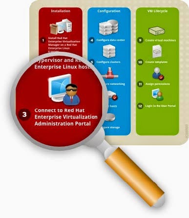
The Red Hat Enterprise Virtualization platform comprises various components which work seamlessly together, enabling the system administrator to install, configure and manage a virtualized environment. After reading this guide, you will be able to set up Red Hat Enterprise Virtualization as represented in the following diagram:
Figure 1.1. Overview of Red Hat Enterprise Virtualization components
Prerequisites
The following requirements are typical for small- to medium-sized installations. Note that the exact
requirements of the setup depend on the specific installation, sizing and load. Please use the following requirements as guidelines:
Red Hat Enterprise Virtualization Manager
- Minimum - Dual core server with 4 GB RAM, with 25 GB free disk space and 1 Gbps network
- interface.
- Recommended - Dual Sockets/Quad core server with 16 GB RAM, 50 GB free disk space on multiple disk spindles and 1 Gbps network interface.
The breakdown of the server requirements are as below:
- For the Red Hat Enterprise Linux 6 operating system: minimum 1 GB RAM and 5 GB local disk space.
- For the Manager: minimum 3 GB RAM, 3 GB local disk space and 1 Gbps network controller
- bandwidth.
- If you wish to create an ISO domain on the Manager server, you need minimum 15 GB disk space.
Note: The Red Hat Enterprise Virtualization Manager setup script, rhevm -setup, supports the
en_US.UT F-8, en_US.utf8, and en_US.utf-8 locales. Ensure that you install the Red Hat
Enterprise Virtualization Manager on a system where the locale in use is one of these
supported values.
A valid Red Hat Network subscription to the following channels:
- The Red Hat Enterprise Virtualization Manager (v.3 x86_64 ) channel, also referred to as rhel-x86_64 -server-6-rhevm -3, which provides Red Hat Enterprise Virtualization Manager.
- The JBoss Application Platform (v 5) for 6Server x86_64 channel, also referred to as jbappplatform -5-x86_64 -server-6-rpm , which provides the supported release of the application platform on which the manager runs.
- The RHEL Server Supplem entary (v. 6 64 -bit x86_64 ) channel, also referred to as rhel-x86_64 -server-supplem entary-6, which provides the supported version of the Java Runtime Environment (JRE).
A client for connecting to Red Hat Enterprise Virtualization Manager.
- Microsoft Windows (7, XP, 2003 or 2008) with Internet Explorer 7 and above
- Microsoft .NET Framework 4
For each Host (Red Hat Enterprise Virtualization Hypervisor or Red Hat Enterprise Linux)
- Minimum - Dual core server, 10 GB RAM and 10 GB Storage, 1 Gbps network interface.
- Recommended - Dual socket server, 16 GB RAM and 50 GB storage, two 1 Gbps network interfaces.
The breakdown of the server requirements are as below:
- For each host: AMD-V or Intel VT enabled, AMD64 or Intel 64 extensions, minimum 1 GB RAM, 3GB free storage and 1 Gbps network interface.
- For virtual machines running on each host: minimum 1 GB RAM per virtual machine.
- Valid Red Hat Network subscriptions for each host. You can use either Red Hat Enterprise Virtualization Hypervisor or Red Hat Enterprise Linux hosts, or both.
For each Red Hat Enterprise Virtualization Hypervisor host:
- The Red Hat Enterprise Virtualization Hypervisor (v.6 x86-64 ) channel, also referred to as rhel-x86_64 -server-6-rhevh
- For each Red Hat Enterprise Virtualization Linux host: The Red Hat Enterprise Virt Management Agent (v 6 x86_64 ) channel, also referred to as rhel-x86_64 -rhevmgm t-agent-6.
Storage and Networking- At leasTone of the supported storage types (NFS, iSCSI and FCP).
- For NFS storage, a valid IP address and export path is required.
- For iSCSI storage, a valid IP address and target information is required.
- Static IP addresses for the Red Hat Enterprise Virtualization Manager server and for each host server.
- DNS service which can resolve (forward and reverse) all the IP addresses.
- An existing DHCP server which can allocate network addresses for the virtual machines.
Virtual Machines- Installation images for creating virtual machines, depending on which operating system you wish to use.
- Microsoft Windows XP, 7, 2003 or 2008.
- Red Hat Enterprise Linux 3, 4, 5 or 6.
- Valid licenses or subscription entitlements for each operating system.
Red Hat Enterprise Virtualization User Portal- A Red Hat Enterprise Linux client running Mozilla Firefox 3.6 and higher or a Windows client running Internet Explorer 7 and higher.
Install Red Hat Enterprise Virtualization
The Red Hat Enterprise Virtualization platform consists of at leasTone Manager and one or more hosts.
Red Hat Enterprise Virtualization Manager provides a graphical user interface to manage the
physical and logical resources of the Red Hat Enterprise Virtualization infrastructure. The Manager is installed on a Red Hat Enterprise Linux 6 server, and accessed from a Windows client running
Internet Explorer.
Red Hat Enterprise Virtualization Hypervisor runs virtual machines. A physical server running
Red Hat Enterprise Linux can also be configured as a host for virtual machines on the Red Hat
Enterprise Virtualization platform.
Install Red Hat Enterprise Virtualization Manager
Figure 2.1. Install Red Hat Enterprise Virtualization Manager
The Manager is the control center of the Red Hat Enterprise Virtualization environment. It allows you to define hosts, configure data centers, add storage, define networks, create virtual machines, manage user permissions and use templates from one central location.
The Red Hat Enterprise Virtualization Manager must be installed on a server running Red Hat
Enterprise Linux 6, with minimum 4 GB RAM, 25 GB free disk space and 1 Gbps network interface.
Install Red Hat Enterprise Linux 6 on a server. When prompted for the software packages to
install, select the default Basic Server option. See the Red Hat Enterprise Linux Installation
Guide for more details.
Note: During installation, remember to set the fully qualified domain name (FQDN) and IP for the
server. If the classpathx-jaf package has been installed, it must be removed because it conflicts with some of the components required to support JBoss in Red Hat Enterprise Virtualization Manager. Run:
# yum remove classpathx-jaf
If your server has not been registered with the Red Hat Network, run:
# rhn_register
To complete registration successfully you need to supply your Red Hat Network username and
password. Follow the onscreen prompts to complete registration of the system.
After you have registered your server, update all the packages on it. Run:
# yum -y update
Reboot your server for the updates to be applied.
Subscribe the server to the required channels using the Red Hat Network web interface.
a. Log on to Red Hat Network (http://rhn.redhat.com/).
b. Click System s at the top of the page.
c. Select the system to which you are adding channels from the list presented on the screen,
by clicking the name of the system.
d. Click Alter Channel Subscriptions in the Subscribed Channels section of the
screen.
e. Select the following channels from the list presented on the screen.
Red Hat Enterprise Virtualization Manager (v.3 x86_64 )
RHEL Server Supplem entary (v. 6 64 -bit x86_64 )
JBoss Application Platform (v 5) for 6Server x86_64 (note that this
channel is listed under "Additional Services Channels for Red Hat Enterprise Linux 6 for
x86_64")
Click the Change Subscription button to finalize the change.
You are now ready to install the Red Hat Enterprise Virtualization Manager. Run the following
command:
# yum -y install rhevm
This command will download the Red Hat Enterprise Virtualization Manager installation software
and resolve all dependencies.
When the packages have finished downloading, run the installer:
# rhevm -setup
Note: rhevm -setup supports the en_US.UT F-8, en_US.utf8, and en_US.utf-8 locales.
You will not be able to run this installer on a system where the locale in use is noTone of
these supported values.The installer will take you through a series of interactive questions as listed in the following
example. If you do not enter a value when prompted, the installer uses the default settings which
are stated in [ ] brackets.
Example: Red Hat Enterprise Virtualization Manager installation
Welcom e to RHEV Manager setup utility
HTTP Port [8080] :
HTTPS Port [8443] :
Host fully qualified Dmain Name, note that this Name should be fully
resolvable [rhevm .dem o.redhat.com ] :
Password for Adm inistrator (adm in@ internal) :
Database password (required for secure authentication with the locally
created database) :
Confirm password :
Organization Name for the Certificate: Red Hat
The default storage type you will be using ['NFS'| 'FC'| 'ISCSI'] [NFS] :
ISCSI
Should the installer configure NFS share on this server to be used as an ISO
Dmain? ['yes'| 'no'] [no] : yes
Mount point path: /data/iso
Display Name for the ISO Dmain: local-iso-share
Firewall ports need to be opened.
You can let the installer configure iptables autom atically overriding the current configuration. The old configuration will be backed up.
Alternately you can configure the firewall later using an example iptables file found under /usr/share/rhevm /conf/iptables.example
Configure iptables ? ['yes'| 'no']: yesImportant points to note:- The default ports 8080 and 84 4 3 must be available to access the manager on HTTP and HTTPS respectively.
- If you elect to configure an NFS share it will be exported from the machine on which the manager is being installed.
- The storage type that you select will be used to create a data center and cluster. You will then be able to attach storage to these from the Administration Portal.
You are then presented with a summary of the configurations you have selected. Type yes to
accept them.
Example: Confirm Manager installation settings
RHEV Manager will be installed using the following configuration:
=================================================================
http-port: 8080
https-port: 8443
host-fqdn: rhevm .dem o.redhat.com
auth-pass: * * * * * * * *
db-pass: * * * * * * * *
org-Name: Red Hat
default-dc-type: ISCSI
nfs-m p: /data/iso
iso-Dmain-Name: local-iso-share
override-iptables: yes
Proceed with the configuration listed above? (yes|no): yes The installation commences. The following message displays, indicating that the installation was
successful.
Example: Successful installation
Installing:
Creating JBoss Profile... [ DONE ]
Creating CA... [ DONE ]
Setting Database Security... [ DONE ]
Creating Database... [ DONE ]
Updating the Default Data Center Storage Type... [ DONE ]
Editing JBoss Configuration... [ DONE ]
Editing RHEV Manager Configuration... [ DONE ]
Configuring the Default ISO Dmain... [ DONE ]
Starting JBoss Service... [ DONE ]
Configuring Firewall (iptables)... [ DONE ]
* * * * Installation com pleted successfully * * * * * *Your Red Hat Enterprise Virtualization Manager is now up and running. You can log in to the Red Hat Enterprise Virtualization Manager's web administration portal with the username adm in (the
administrative user configured during installation) in the internal domain. Instructions to do so are
provided at the end of this chapter.
Important: The internal domain is automatically created upon installation, however no new users can be added to this domain. To authenticate new users, you need an external directory service. Red Hat
Enterprise Virtualization supports IPA and Active Directory, and provides a utility called rhevmmanage-domains to attach new directories to the system.Install Hosts
Figure 2.2. Install Red Hat Enterprise Virtualization Hosts
After you have installed the Red Hat Enterprise Virtualization Manager, install the hosts to run your
virtual machines. In Red Hat Enterprise Virtualization, you can use either Red Hat Enterprise
Virtualization Hypervisor or Red Hat Enterprise Linux as hosts.
Install Red Hat Enterprise Virtualization Hypervisor
This document provides instructions for installing the Red Hat Enterprise Virtualization Hypervisor using a CD. For alternative methods including PXE networks or USB devices, see the Red Hat Enterprise Linux Hypervisor Deployment Guide.
Before installing the Red Hat Enterprise Virtualization Hypervisor, you need to download the hypervisor image from the Red Hat Network and create a bootable CD with the image. This procedure can be performed on any machine running Red Hat Enterprise Linux.
To prepare a Red Hat Enterprise Virtualization Hypervisor installation CD- Download the latest version of the rhev-hypervisor* package from Red Hat Network. The lisTof hypervisor packages is located at the Red Hat Enterprise Virtualization Hypervisor
(v.6 x86_64 ) channel.
a. Log on to Red Hat Network (http://rhn.redhat.com/).
b. Click System s at the top of the page.
c. From the list presented on the screen, select the system on which the Red Hat Enterprise
Virtualization Manager is installed by clicking on its name.
d. Click Alter Channel Subscriptions in the Subscribed Channels section of the screen.
e. Select the Red Hat Enterprise Virtualization Hypervisor (v.6 x86_64 ) channel from the list presented on the screen, then click the Change Subscription button to finalize the change.
Log in to the system on which the Red Hat Enterprise Virtualization Manager is installed. You must log in as the root user to install the rhev-hypervisor package. Run the following command:
# yum install "rhev-hypervisor* "
The hypervisor ISO image is installed into the /usr/share/rhev-hypervisor/ directory.Insert a blank CD into your CD writer. Use the cdrecord utility to burn the hypervisor ISO image
onto your disc. Run:
# cdrecord dev=/dev/cdrw /usr/share/rhev-hypervisor/rhev-hypervisor.iso
You have created a Red Hat Enterprise Virtualization Hypervisor installation CD, now you can use it to boot the machine designated as your hypervisor host. For this guide you will use the interactive installation where you are prompted to configure your settings in a graphical interface. Use the following keys to navigate around the installation screen:
Menu Navigation Keys
Use the Up and Down arrow keys to navigate between selections. Your selections are highlighted in white.
The T ab key allows you to move between fields.
Use the Spacebar to tick checkboxes, represented by [ ] brackets. A marked checkbox displays
with an asterisk (* ).
To proceed with the selected configurations, press the Enter key.
To configure Red Hat Enterprise Virtualization Hypervisor installation settings
Insert the Red Hat Enterprise Virtualization Hypervisor 6.2-3.0 installation CD into your CD-ROM
drive and reboot the machine. When the boot splash screen displays, press the T ab key and
select Boot to boot from the hypervisor installation media. Press Enter.
On the installation confirmation screen, select Install RHEV Hypervisor and press Enter.
The installer automatically detects the drives attached to the system. The selected disk for
booting the hypervisor is highlighted in white. Ensure that the local disk is highlighted, otherwise
use the arrow keys to select the correct disk. Select Continue and press Enter.
You are prompted to confirm your selection of the local drive, which is marked with an asterisk.
Select Continue and press Enter.
Enter a password for local console access and confirm it. Select Install and press Enter. The
Red Hat Enterprise Virtualization Hypervisor partitions the local drive, then commences
installation.
Once installation is complete, a dialog prompts you to Reboot the hypervisor. Press Enter to
confirm. Remove the installation disc.
After the hypervisor has rebooted, you will be taken to a login shell. Log in as the adm in user with
the password you provided during installation to enter the Red Hat Enterprise Virtualization
Hypervisor management console.
On the hypervisor management console, there are eight tabs on the left. Press the Up and Down
keys to navigate between the tabs and Enter to access them.
Select the Network tab. Configure the following options:
HostName: Enter the hostname in the formaTof hostName.Dmain.example.com .
DNS Server: Enter the Domain Name Server address in the formaTof 192.168.0.254 . You can use up to two DNS servers.
NTP Server: Enter the Network T ime Protocol server address in the formaTof rhel.pool.ntp.org. This synchronizes the hypervisor's system clock with thaTof the manager's. You can use up to two NTP servers. Select Apply and press Enter to save your network settings.
The installer automatically detects the available network interface devices to be used as the management network. Select the device and press Enter to access the interface configuration menu. Under IPv4 Settings, tick either the DHCP or Static checkbox.
If you are using static IPv4 network configuration, fill in the IP Address, Netm ask and Gateway fields.
To confirm your network settings, selecToK and press Enter.
Select the RHEV-M tab. Configure the following options:
Managem ent Server: Enter the Red Hat Enterprise Virtualization Manager domain name in the formaTof rhevm .dem o.redhat.com.
Management Server Port: Enter the management server port number. The default is 8443.
Connect to the RHEV Manager and Validate Certificate: Tick this checkbox if you wish to verify the RHEVM security certificate.
Set RHEV-M Adm in Password: This field allows you to specify the root password for the hypervisor, and enable SSH password authentication from the Red Hat Enterprise Virtualization Manager.
Select Apply and press Enter. A dialog displays, asking you to connect the hypervisor to the Red Hat Enterprise Virtualization Manager and validate its certificate. Select Approve and press Enter. A message will display notifying you that the manager configuration has been successfully updated.
Under the Red Hat Network tab, you can register the host with the Red Hat Network.
This enables the host to run Red Hat Enterprise Linux virtual machines with proper RHN entitlements. Configure the following settings:
Enter your Red Hat Network credentials in the Login and Password fields.
To select the method by which the hypervisor receives updates, tick either the RHN or Satellite checkboxes. Fill in the RHN URL and RHN CA fields.
To confirm your RHN settings, select Apply and press Enter.
Accept all other default settings. For information on configuring security, logging, kdump and
remote storage
Finally, select the Status tab. Select Restart and press Enter to reboot the host and
apply all changes.
You have now successfully installed the Red Hat Enterprise Virtualization Hypervisor. Repeat this
procedure if you wish to use more hypervisors. The following sections will provide instructions on how to approve the hypervisors for use with the Red Hat Enterprise Virtualization Manager.
Install Red Hat Enterprise Linux Host
You now know how to install a Red Hat Enterprise Virtualization Hypervisor. In addition to hypervisor hosts, you can also reconfigure servers which are running Red Hat Enterprise Linux to be used as virtual machine hosts.
To install a Red Hat Enterprise Linux 6 host
On the machine designated as your Red Hat Enterprise Linux host, install Red Hat Enterprise
Linux 6.2. SelecTonly the Base package group during installation.
If your server has not been registered with the Red Hat Network, run the rhn_register command as root to register it. To complete registration successfully you will need to supply your Red Hat Network username and password. Follow the onscreen prompts to complete registration of the system.
# rhn_register
Subscribe the server to the required channels using the Red Hat Network web interface.
Log on to Red Hat Network (http://rhn.redhat.com/).
b. Click System s at the top of the page.
c. Select the system to which you are adding channels from the list presented on the screen,
by clicking the name of the system.
d. Click Alter Channel Subscriptions in the Subscribed Channels section of the
screen.
e. Select the Red Hat Enterprise Virt Managem ent Agent (v 6 x86_64 ) channel
from the list presented on the screen, then click the Change Subscription button to
finalize the change.
Red Hat Enterprise Virtualization platform uses a number of network ports for management and
other virtualization features. Adjust your Red Hat Enterprise Linux host's firewall settings to allow
access to the required ports by configuring iptables rules. Modify the /etc/sysconfig/iptables file so it resembles the following example:
:INPUT ACCEPT [0:0]
:FORWARD ACCEPT [0:0]
:OUTPUT ACCEPT [10765:598664]
-A INPUT -m state --state RELATED,ESTABLISHED -j ACCEPT
-A INPUT -p icm p -j ACCEPT
-A INPUT -i lo -j ACCEPT
-A INPUT -p tcp --dport 22 -j ACCEPT
-A INPUT -p tcp --dport 16514 -j ACCEPT
-A INPUT -p tcp --dport 54321 -j ACCEPT
-A INPUT -p tcp -m m ultiport --dports 5634:6166 -j ACCEPT
-A INPUT -p tcp -m m ultiport --dports 49152:49216 -j ACCEPT
-A INPUT -p tcp -m state --state NEW
-A INPUT -j REJECT --reject-with icm p-host-prohibited
-A FORWARD -m physdev ! --physdev-is-bridged -j REJECT --reject-with icm phost-
prohibited
COMMIT
Ensure that the iptables service is configured to starTon boot and has been restarted, or started for the first time if it was not already running. Run the following commands:
# chkconfig iptables on
# service iptables restart
You have now successfully installed a Red Hat Enterprise Linux host. As before, repeat this procedure if you wish to use more Linux hosts. Before you can start running virtual machines on your host, you have to manually add it to the Red Hat Enterprise Virtualization Manager via the administration portal, which you will access in the next step.
Figure 2.3. Connect to the Manager administration portal
Now that you have installed the Red Hat Enterprise Virtualization Manager and hosts, you can log in to the Manager administration portal to start configuring your virtualization environment. The web-based administration portal can be accessed using a Windows client running Internet Explorer.
Before logging in, install .NET Framework 4 and modify the default security settings on the machine used to access the web administration portal. The example below is applicable for Windows 2008.
To configure Windows client to access the administration portal
To install .NET Framework 4, download it from
http://www.microsoft.com/download/en/details.aspx?id=17718. Run this executable as a user with administration access to the system.
Next, disable Internet Explorer Enhanced Security Configuration. Click Start → Administrative
Tools → Server Manager. On the Security Inform ation pane in the Server Manager window, click Configure IE ESC. SelecToff for Administrators and Users to disable the security configuration. Click OK.
To add the administration portal to the browser's lisTof trusted sites, open a browser and click on
Tools → InterneToptions. Click on the Security tab.
Select Trusted Sites. Click Sites to display the T rusted Sites dialog. Enter the URL for your administration portal in the Add this website to the zone textbox. Click Add, then Close.
Click the Custom Level... button. Locate the XAML browser applications item in the list, ensure that it is set to Enable, then click OK.
Restart Internet Explorer to access the administration portal.
Log In to Administration Portal
Now that the prerequisites have been resolved, you can log in to the Red Hat Enterprise Virtualization
Manager administration portal. Ensure that you have the administrator password configured during
installation as instructed in Example, “Red Hat Enterprise Virtualization Manager installation”.
To connect to Red Hat Enterprise Virtualization web management portal
Open a browser and navigate to https://Dmain.exam ple.com :84 4 3/RHEVManager.
Substitute Dmain.exam ple.com with the URL provided during installation.
If this is your first time connecting to the administration portal, Red Hat Enterprise Virtualization
Manager will issue security certificates for your browser. Click the link labelled this certificate to trust the ca.cer certificate. A pop-up displays, click Open to launch the Certificate dialog. Click Install Certificate and select to place the certificate in Trusted Root Certification Authorities store.
Back on the browser screen, click the link labelled here and follow the prompts to install the RHEV-GUI-CertificateInstaller executable. A pop-up displays again, this time click Run.
Note that the actual certificate installation is preceded by an ActiveX installation.
When complete, a new link labelled here appears. Click on it to reload the administration portal.
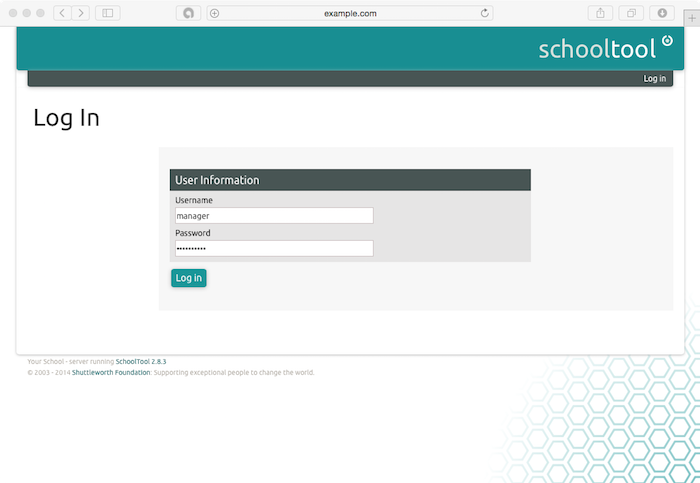
The portal login screen displays. Enter adm in as your User Name, and enter the Password
that you provided during installation. Ensure that your domain is set to Internal. Click Login.
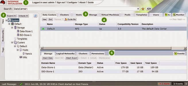
You have now successfully logged in to the Red Hat Enterprise Virtualization web administration portal. Here, you can configure and manage all your virtual resources. The functions of the Red Hat Enterprise Virtualization Manager graphical user interface are described in the following figure and list:
Figure 2.4 . Administration Portal Features
Header: This bar contains the name of the logged in user, the sign out button, the option to
configure user roles.
Navigation Pane: This pane allows you to navigate between the Tree, Bookmarks and Tags tabs. In the Tree tab, tree mode allows you to see the entire system tree and provides a visual representation your virtualization environment's architecture.
Resources Tabs: These tabs allow you to access the resources of Red Hat Enterprise Virtualization. You should already have a Default Data Center, a Default Cluster, a Host waiting to be approved, and available Storage waiting to be attached to the data center.
Results List: When you select a tab, this list displays the available resources. You can perform
a task on an individual item or multiple items by selecting the item(s) and then clicking the relevant
action button. If an action is not possible, the button is disabled.
Details Pane: When you select a resource, this pane displays its details in several subtabs.
These subtabs also contain action buttons which you can use to make changes to the selected
resource.
Once you are familiar with the layouTof the administration portal, you can start configuring your virtual environment.
Configure Red Hat Enterprise Virtualization
Now that you have logged in to the administration portal, configure your Red Hat Enterprise Virtualization environment by defining the data center, host cluster, networks and storage. Even though this guide makes use of the default resources configured during installation, if you are setting up a Red Hat Enterprise Virtualization environment with completely new components, you should perform the configuration procedure in the sequence given here.
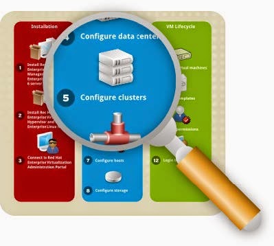
Configure Data Centers
Figure 3.1. Configure Data Center
A data center is a logical entity that defines the seTof physical and logical resources used in a managed virtual environment. Think of it as a container which houses clusters of hosts, virtual machines, storage and networks.
By default, Red Hat Enterprise Virtualization creates a data center at installation. Its type is configured from the installation script. To access it, navigate to the Tree pane, click Expand All, and select the Default data center. On the Data Centers tab, the Default data center displays.
Figure 3.2. Data Centers Tab
The Default data center is used for this document, however if you wish to create a new data center
see the Red Hat Enterprise Virtualization Administration Guide.
Configure Cluster
Figure 3.3. Populate Cluster with Hosts
A cluster is a seTof physical hosts that are treated as a resource pool for a seTof virtual machines.
Hosts in a cluster share the same network infrastructure, the same storage and the same type of CPU.
They constitute a migration domain within which virtual machines can be moved from host to host.
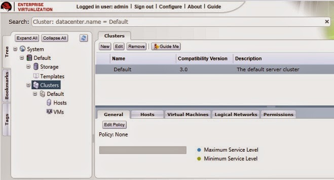
By default, Red Hat Enterprise Virtualization creates a cluster at installation.
To access it, navigate to the Tree pane, click Expand All and select the Default cluster. On the Clusters tab, the Default
Figure 3.4 . Clusters Tab
For this document, the Red Hat Enterprise Virtualization Hypervisor and Red Hat Enterprise Linux hosts will be attached to the Default host cluster. If you wish to create new clusters, or live migrate virtual machines between hosts in a cluster, see the Red Hat Enterprise Virtualization Evaluation Guide.
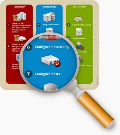
Configure Networking
Figure 3.5. Configure Networking
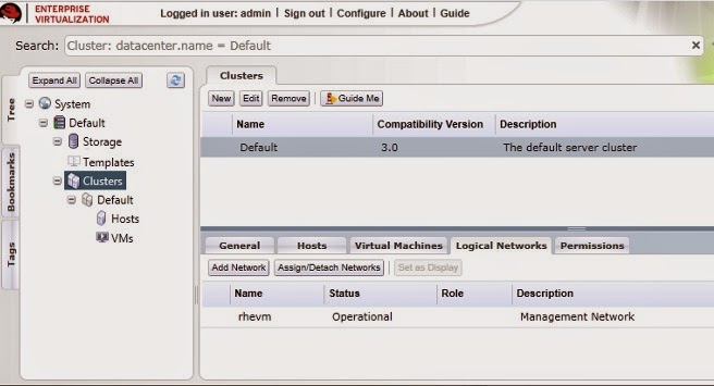
At installation, Red Hat Enterprise Virtualization defines a Management network for the default data center. This network is used for communication between the manager and the host. New logical networks - for example for guest data, storage or display - can be added to enhance network speed and performance. All networks used by hosts and clusters must be added to data center they belong to.
To access the Management network, click on the Clusters tab and select the default cluster. Click the Logical Networks tab in the Details pane. The rhevm network displays.
Figure 3.6. Logical Networks Tab
The rhevm Management network is used for this document, however if you wish to create new logical networks see the Red Hat Enterprise Virtualization Administration Guide.
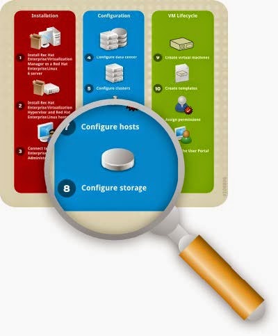
Configure Hosts
Figure 3.7. Configure Hosts
You have already installed your Red Hat Enterprise Virtualization Hypervisor and Red Hat Enterprise
Linux hosts, but before they can be used, they have to be added to the Manager. The Red Hat
Enterprise Virtualization Hypervisor is specifically designed for the Red Hat Enterprise Virtualization
platform, therefore iTonly needs a simple click of approval. Conversely, Red Hat Enterprise Linux is a general purpose operating system, therefore reprogramming it as a host requires additional
configuration.
Approve Red Hat Enterprise Virtualization Hypervisor Host
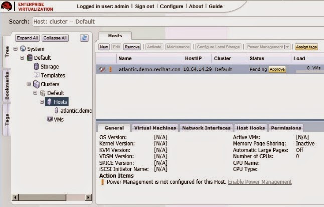
The Hypervisor you installed in Section “Install Red Hat Enterprise Virtualization Hypervisor” is automatically registered with the Red Hat Enterprise Virtualization platform. It displays in the Red Hat Enterprise Virtualization Manager, and needs to be approved for use.
To set up a Red Hat Enterprise Virtualization Hypervisor hostOn the Tree pane, click Expand All and select Hosts under the Default cluster. On the Hosts tab, select the name of your newly installed hypervisor.
Figure 3.8. Red Hat Enterprise Virtualization Hypervisor pending approval
Click the Approve button. The Edit and Approve Host dialog displays. Accept the defaults
or make changes as necessary, then click OK.
Figure 3.9. Approve Red Hat Enterprise Virtualization Hypervisor
The host status will change from Non Operational to Up.
Attach Red Hat Enterprise Linux Host
In contrast to the hypervisor host, the Red Hat Enterprise Linux host you installed in Section,
“Install Red Hat Enterprise Linux Host” is not automatically detected. It has to be manually attached to the Red Hat Enterprise Virtualization platform before it can be used.
To attach a Red Hat Enterprise Linux hostOn the Tree pane, click Expand All and select Hosts under the Default cluster. On the Hosts
tab, click New.
The New Host dialog displays.
Figure 3.10. Attach Red Hat Enterprise Linux Host
Enter the details in the following fields:
- Data Center: the data center to which the host belongs. Select the Default data center.
- Host Cluster: the cluster to which the host belongs. Select the Default cluster.
- Name: a descriptive name for the host.
- Address: the IP address, or resolvable hostname of the host, which was provided during installation.
- Root Password: the password of the designated host; used during installation of the host.
- Configure iptables rules: This checkbox allows you to override the firewall settings on the host with the default rules for Red Hat Enterprise Virtualization.
If you wish to configure this host for OuTof Band (OOB) power management, select the Power Managem ent tab. T ick the Enable Power Managem ent checkbox and provide the required information in the following fields:
- Address: The address of the host.
- User Name: A valid user name for the OOB management.
- Password: A valid, robust password for the OOB management.
- Type: The type of OOB management device. Select the appropriate device from the drop down list.
alom Sun Advanced Lights Out Manager
apc American Power Conversion Master
MasterSwitch network power switch
bladecenter IBM Bladecentre Remote Supervisor Adapter
drac5 Dell Remote Access Controller for Dell
computers
eps ePowerSwitch 8M+ network power switch
ilo HP Integrated Lights Out standard
ilo3 HP Integrated Lights Out 3 standardipmilan Intelligent Platform Management Interface
rsa IBM Remote Supervisor Adaptor
rsb Fujitsu-Siemens RSB management interface
wti Western T elematic Inc Network PowerSwitch
cisco_ucs Cisco Unified Computing System Integrated
Management Controller - Options: Extra command line options for the fence agent. Detailed documentation of the options available is provided in the man page for each fence agent.
Click the Test button to test the operation of the OOB management solution.
If you do not wish to configure power management, leave the Enable Power Management checkbox unmarked.
Click OK. If you have not configured power management, a pop-up window prompts you to confirm if you wish to proceed without power management. SelecToK to continue.
The new host displays in the lisTof hosts with a status of Installing. Once installation is complete, the status will update to Reboot and then Awaiting. When the host is ready for use, its status changes to Up.
You have now successfully configured your hosts to run virtual machines. The next step is to prepare data storage domains to house virtual machine disk images.
Configure Storage
Figure 3.11. Configure Storage
After configuring your logical networks, you need to add storage to your data center.
Red Hat Enterprise Virtualization uses a centralized shared storage system for virtual machine disk
images and snapshots. Storage can be implemented using Network File System (NFS), Internet Small
Computer System Interface (iSCSI) or Fibre Channel Protocol (FCP). Storage definition, type and function, are encapsulated in a logical entity called a Storage Dmain. Multiple storage domains are
supported.
For this guide you will use two types of storage domains. The first is an NFS share for ISO images of installation media. You have already created this ISO domain during the Red Hat Enterprise Virtualization Manager installation
The second storage domain will be used to hold virtual machine disk images. For this domain, you need at leasTone of the supported storage types. You have already set a default storage type during
installation as described in Section, “Install Red Hat Enterprise Virtualization Manager”. Ensure that you use the same type when creating your data domain.
Select your next step by checking the storage type you should use:- Navigate to the Tree pane and click the Expand All button. Under System, click Default. On
the results list, the Default data center displays. - On the results list, the Storage T ype column displays the type you should add.
- Now that you have verified the storage type, create the storage domain:
For NFS storage, refer to Section, “Create an NFS Data Domain”.
For iSCSI storage, refer to Section, “Create an iSCSI Data Domain”.
For FCP storage, refer to Section, “Create an FCP Data Domain”.
Create an NFS Data Domain
Because you have selected NFS as your default storage type during the Manager installation, you will
now create an NFS storage domain. An NFS type storage domain is a mounted NFS share that is
attached to a data center and used to provide storage for virtual machine disk images.
To add NFS storage:Navigate to the Tree pane and click the Expand All button. Under System, select the Default
data center and click on Storage. The available storage domains display on the results list. Click
New Domain.
The New Storage dialog box displays.
Figure 3.12. Add New Storage
Configure the following options:
- Name: Enter a suitably descriptive name.
- Data Center: The Default data center is already pre-selected.
- Dmain Function / Storage T ype: In the drop down menu, select Data → NFS. The storage domain types not compatible with the Default data center are grayed out. After you select your domain type, the Export Path field appears.
- Use Host: Select any of the hosts from the drop down menu. Only hosts which belong in the pre-selected data center will display in this list.
- Export path: Enter the IP address or a resolvable hostname of the chosen host. The export path should be in the formaTof 192.168.0.10:/data or domain.example.com :/data
Click OK. The new NFS data domain displays on the Storage tab. It will remain with a Locked status while it is being prepared for use. When ready, it is automatically attached to the data center.
You have created an NFS storage domain. Now, you need to attach an ISO domain to the data center
and upload installation images so you can use them to create virtual machines. Proceed to Section, “Attach and Populate ISO domain”.
Create an iSCSI Data Domain
Because you have selected iSCSI as your default storage type during the Manager installation, you will now create an iSCSI storage domain. Red Hat Enterprise Virtualization platform supports iSCSI storage domains spanning multiple pre-defined Logical Unit Numbers (LUNs).
To add iSCSI storage:
On the side pane, select the Tree tab. On System , click the + icon to display the available data
centers.
Double click on the Default data center and click on Storage. The available storage domains
display on the results list. Click New Domain.
The New Dmain dialog box displays.
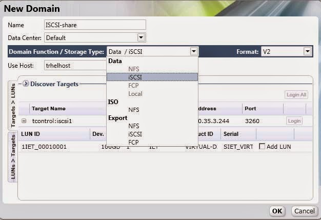
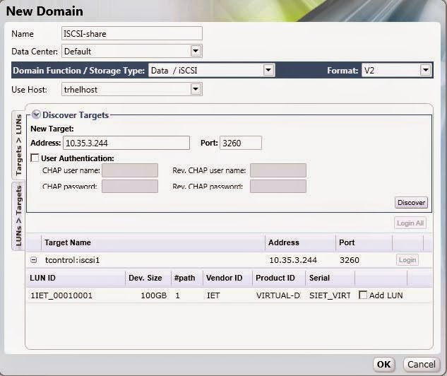
Figure 3.13. Add iSCSI Storage
Configure the following options:
- Name: Enter a suitably descriptive name.
- Data Center: The Default data center is already pre-selected.
- Domain Function / Storage Type: In the drop down menu, select Data → iSCSI.
- The storage domain types which are not compatible with the Default data center are grayed out. After you select your domain type, the Use Host and Discover T argets fields display.
- Use host: Select any of the hosts from the drop down menu. Only hosts which belong in this data center will display in this list.
To connect to the iSCSI target, click the Discover Targets bar. This expands the menu to
display further connection information fields.
Figure 3.14 . Attach LUNs to iSCSI domain
Enter the required information:
- Address: Enter the address of the iSCSI target.
- Port: Select the port to connect to. The default is 3260.
- User Authentication: If required, enter the username and password.
Click the Discover button to find the targets. The iSCSI targets display in the results list with a
Login button for each target.
Click Login to display the lisTof existing LUNs. Tick the Add LUN checkbox to use the selected
LUN as the iSCSI data domain.
Click OK. The new NFS data domain displays on the Storage tab. It will remain with a Locked
status while it is being prepared for use. When ready, it is automatically attached to the data
center.
You have created an iSCSI storage domain. Now, you need to attach an ISO domain to the data center
and upload installation images so you can use them to create virtual machines. Proceed to Section ,“Attach and Populate ISO domain”.
Create an FCP Data Domain
Because you have selected FCP as your default storage type during the Manager installation, you will
now create an FCP storage domain. Red Hat Enterprise Virtualization platform supports FCP storage domains spanning multiple pre-defined Logical Unit Numbers (LUNs).
To add FCP storage:
On the side pane, select the Tree tab. On System , click the + icon to display the available data
centers.
Double click on the Default data center and click on Storage. The available storage domains
display on the results list. Click New Domain.
The New Dmain dialog box displays.
Figure 3.15. Add FCP Storage
Configure the following options:
- Name: Enter a suitably descriptive name.
- Data Center: The Default data center is already pre-selected.
- Domain Function / Storage Type: Select FCP.
- Use Host: Select the IP address of either the hypervisor or Red Hat Enterprise Linux host.
- The lisTof existing LUNs display. On the selected LUN, tick the Add LUN checkbox to use it as the FCP data domain.
Click OK. The new FCP data domain displays on the Storage tab. It will remain with a Locked
status while it is being prepared for use. When ready, it is automatically attached to the data
center.
You have created an FCP storage domain. Now, you need to attach an ISO domain to the data center
and upload installation images so you can use them to create virtual machines. Proceed to Section, “Attach and Populate ISO domain”.
Attach and Populate ISO domain
You have defined your first storage domain to store virtual guest data, now it is time to configure your second storage domain, which will be used to store installation images for creating virtual machines. You have already created a local ISO domain during the installation of the Red Hat Enterprise Virtualization Manager. To use this ISO domain, attach it to a data center.
To attach the ISO domainNavigate to the Tree pane and click the Expand All button. Click Default. On the results list,
the Default data center displays.
On the details pane, select the Storage tab and click the Attach ISO button.
The Attach ISO Library dialog appears with the available ISO domain. Select it and click OK.
Figure 3.16. Attach ISO Library
The ISO domain appears in the results lisTof the Storage tab. It displays with the Locked status
as the domain is being validated, then changes to Inactive.
Select the ISO domain and click the Activate button. The status changes to Locked and then to
Active.
Media images (CD-ROM or DVD-ROM in the form of ISO images) must be available in the ISO repository for the virtual machines to use. To do so, Red Hat Enterprise Virtualization provides a utility that copies the images and sets the appropriate permissions on the file. The file provided to the utility and the ISO share have to be accessible from the Red Hat Enterprise Virtualization Manager.
Log in to the Red Hat Enterprise Virtualization Manager server console to upload images to the ISO
domain.
To upload ISO imagesCreate or acquire the appropriate ISO images from boot media. Ensure the path to these images
is accessible from the Red Hat Enterprise Virtualization Manager server.
The next step is to upload these files. First, determine the available ISO domains by running:
# rhevm -iso-uploader list
You will be prompted to provide the admin user password which you use to connect to the
administration portal. The tool lists the name of the ISO domain that you attached in the previous
section.
ISO Storage Dmain List:
local-iso-share
Now you have all the information required to upload the required files. On the Manager console,
copy your installation images to the ISO domain. For your images, run:
# rhevm -iso-uploader upload -i local-iso-share [file1] [file2] .... [fileN]
You will be prompted for the admin user password again, provide it and press Enter.
Note that the uploading process can be time consuming, depending on your storage performance.
After the images have been uploaded, check that they are available for use in the Manager
administration portal.
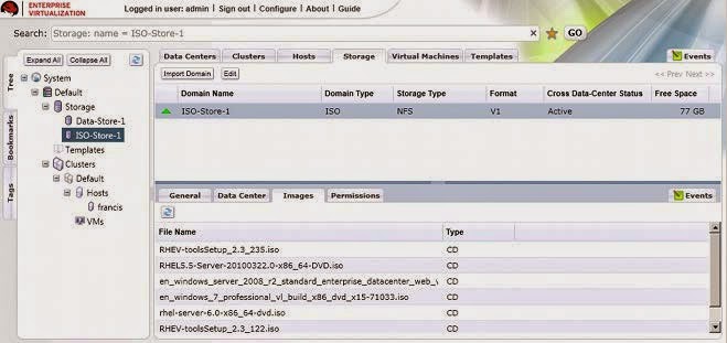
- Navigate to the Tree and click the Expand All button.
- Under Storage, click on the name of the ISO domain. It displays in the results list. Click on it to display its details pane.
- On the details pane, select the Im ages tab. The lisTof available images should be populated with the files which you have uploaded. In addition, the RHEV-toolsSetup.iso and virtio-win.vfd images should have been automatically uploaded during installation.
Figure 3.17. Uploaded ISO images
Now that you have successfully prepared the ISO domain for use, you are ready to start creating virtual machines.
Manage Virtual Machines
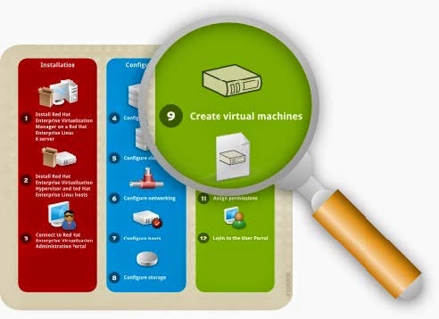
The final stage of setting up Red Hat Enterprise Virtualization is the virtual machine lifecycle - spanning the creation, deployment and maintenance of virtual machines; using templates; and configuring user permissions. This chapter will also show you how to log in to the user portal and connect to virtual machines.
Create Virtual Machines Figure 4 .1. Create Virtual Machines
On Red Hat Enterprise Virtualization, you can create virtual machines from an existing template, as a
clone, or from scratch. Once created, virtual machines can be booted using ISO images, a network boot (PXE) server, or a hard disk. This document provides instructions for creating a virtual machine using an ISO image.
In your current configuration, you should have at leasTone host available for running virtual machines, and uploaded the required installation images to your ISO domain. This section guides you through the creation of a Red Hat Enterprise Linux 6 virtual server. You will perform a normal attended installation using a virtual DVD.
To create a Red Hat Enterprise Linux serverNavigate to the Tree pane and click Expand All. Click the VMs icon under the Default cluster.
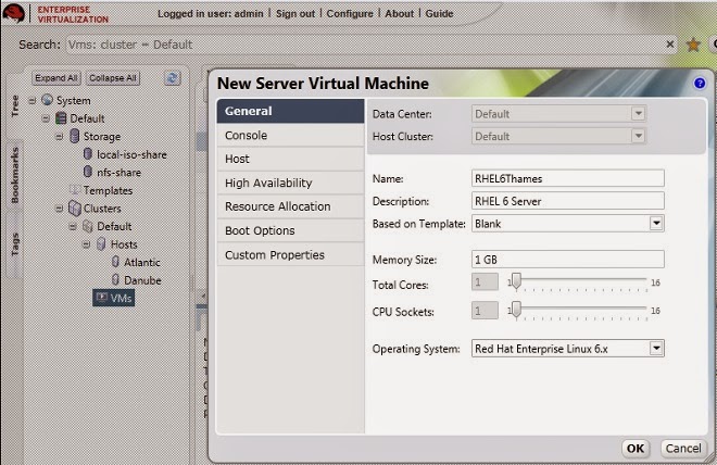
On the Virtual Machines tab, click New Server.
Figure 4 .2. Create New Linux Virtual Machine
You only need to fill in the Name field and select Red Hat Enterprise Linux 6.x as your
Operating System . You may alter other settings but in this example we will retain the defaults.
Click OK to create the virtual machine.
A New Virtual Machine - Guide Me window opens. This allows you to add networks and
storage disks to the virtual machine.
Figure 4 .3. Create Virtual Machines
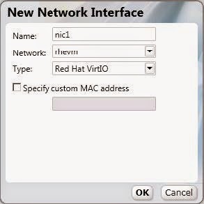
Click Configure Network Interfaces to define networks for your virtual machine. The parameters in the following figure are recommended, but can be edited as necessary. When you have configured your required settings, click OK.
Figure 4 .4 . New Network Interface configurations
You are returned to the Guide Me window. This time, click Configure Virtual Disks to add
storage to the virtual machine. The parameters in the following figure are recommended, but can
be edited as necessary. When you have configured your required settings, click OK.
Figure 4 .5. New Virtual Disk configurations
Close the Guide Me window by clicking Configure Later. Your new RHEL 6 virtual machine will
display in the Virtual Machines tab.
You have now created your first Red Hat Enterprise Linux virtual machine. Before you can use your
virtual machine, install an operating system on it.
To install the Red Hat Enterprise Linux guesToperating system
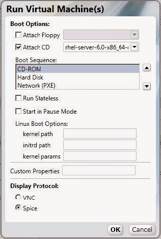
Right click the virtual machine and select Run Once. Configure the following options:
Figure 4 .6. Run Red Hat Enterprise Linux Virtual Machine
- Attach CD: Red Hat Enterprise Linux 6
- Boot Sequence: CD-ROM
- Display protocol: SPICE
Retain the default settings for the other options and click OK to start the virtual machine.
Select the virtual machine and click the Console icon. As this is your first time connecting to
the virtual machine, allow the installation of the Spice Active X and the SPICE client.
After the SPICE plugins have been installed, select the virtual machine and click the Console icon
again. This displays a window to the virtual machine, where you will be prompted to begin installing the operating system.
After the installation has completed, shut down the virtual machine and reboot from the hard drive.
You can now connect to your Red Hat Enterprise Linux virtual machine and start using it.
Create a Windows Virtual Machine
You now know how to create a Red Hat Enterprise Linux virtual machine from scratch. The procedure of creating a Windows virtual machine is similar, except that it requires additional virtio drivers. This example uses Windows 7, but you can also use other Windows operating systems. You will perform a normal attended installation using a virtual DVD.
To create a Windows desktopNavigate to the Tree pane and click Expand All. Click the VMs icon under the Default cluster.
On the Virtual Machines tab, click New Desktop.
Figure 4 .7. Create New Windows Virtual Machine
You only need to fill in the Name field and select Windows 7 as your Operating System . You
may alter other settings but in this example we will retain the defaults. Click OK to create the virtual
machine.
A New Virtual Machine - Guide Me window opens. This allows you to define networks for
the virtual machine. Click Configure Network Interfaces. See Figure 4.4, “New Network
Interface configurations” for details.
You are returned to the Guide Me window. This time, click Configure Virtual Disks to add
storage to the virtual machine. See Figure 4.5, “New Virtual Disk configurations” for details.
Close the Guide Me windows. Your new Windows 7 virtual machine will display in the Virtual
Machines tab.
To install Windows guesToperating systemRight click the virtual machine and select Run Once. The Run Once dialog displays as in
Figure 4.6, “Run Red Hat Enterprise Linux Virtual Machine”. Configure the following options:
- Attach Floppy: virtio-win
- Attach CD: Windows 7
- Boot sequence: CD-ROM
- Display protocol: SPICE
Retain the default settings for the other options and click OK to start the virtual machine.
Select the virtual machine and click the Console icon. This displays a window to the virtual
machine, where you will be prompted to begin installing the operating system.
Accept the default settings and enter the required information as necessary. The only change you must make is to manually install the VirtIO drivers from the virtual floppy disk (vfd) image. To do so, select the Custom (advanced) installation option and click Load Driver. Press Ctrl and select:
- Red Hat VirtIO Ethernet Adapter
- Red Hat VirtIO SCSI Controller
The installation process commences, and the system will reboot itself several times.
Back on the administration portal, when the virtual machine's status changes back to Up, right click on it and select Change CD. From the lisTof images, select RHEV-toolsSetup to attach the Guest Tools ISO which provides features including USB redirection and SPICE display optimization.
Click Console and log in to the virtual machine. Locate the CD drive to access the contents of the Guest Tools ISO, and launch the RHEV-toolsSetup executable. After the tools have been installed, you will be prompted to restart the machine for changes to be applied.
You can now connect to your Windows virtual machine and start using it.
Using Templates
Figure 4 .8. Create Templates
Now that you know how to create a virtual machine, you can save its settings into a template. This template will retain the original virtual machine's configurations, including virtual disk and network interface settings, operating systems and applications. You can use this template to rapidly create replicas of the original virtual machine.
Create a Red Hat Enterprise Linux Template
To make a Red Hat Enterprise Linux virtual machine template, use the virtual machine you created in Section, “Create a Red Hat Enterprise Linux Virtual Machine” as a basis. Before it can be used, it has to be sealed. This ensures that machine-specific settings are not propagated through the template.
To prepare a Red Hat Enterprise Linux virtual machine for use as a templateConnect to the Red Hat Enterprise Linux virtual machine to be used as a template. Flag the
system for re-configuration by running the following command as root:
# touch /.unconfigured
Remove ssh host keys. Run:
# rm -rf /etc/ssh/ssh_host_*
Shut down the virtual machine. Run:
# poweroff
The virtual machine has now been sealed, and is ready to be used as a template for Linux virtual
machines.
To create a template from a Red Hat Enterprise Linux virtual machineIn the administration portal, click the Virtual Machines tab. Select the sealed Red Hat
Enterprise Linux 6 virtual machine. Ensure that it has a status of Down.
Click Make Template. The New Virtual Machine Template displays.
Click Make Template. The New Virtual Machine Template displays.
Figure 4 .9. Make new virtual machine template
Enter information into the following fields:
- Name: Name of the new template
- Description: Description of the new template
- Host Cluster: The Host Cluster for the virtual machines using this template.
- Make Private: If you tick this checkbox, the template will only be available to the template's creator and the administrative user. Nobody else can use this template unless they are given permissions by the existing permitted users.
Click OK. The virtual machine displays a status of "Image Locked" while the template is being
created. The template is created and added to the Templates tab. During this time, the action
buttons for the template remain disabled. Once created, the action buttons are enabled and the
template is ready for use.
Clone a Red Hat Enterprise Linux Virtual Machine
In the previous section, you created a Red Hat Enterprise Linux template complete with pre-configured storage, networking and operating system settings. Now, you will use this template to deploy a preinstalled virtual machine.
To clone a Red Hat Enterprise Linux virtual machine from a templateNavigate to the Tree pane and click Expand All. Click the VMs icon under the Default cluster.
On the Virtual Machines tab, click New Server.
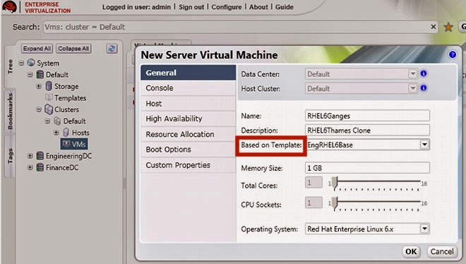
Figure 4 .10. Create virtual machine based on Linux template
On the General tab, select the existing Linux template from the Based on Template
list.
Enter a suitable Name and appropriate Description, then accept the default values
inherited from the template in the resTof the fields. You can change them if needed.
Click the Resource Allocation tab. On the Provisioning field, click the drop down
menu and select the Clone option.
Figure 4 .11. Set the provisioning to Clone
Retain all other default settings and click OK to create the virtual machine. The virtual machine
displays in the Virtual Machines list.
Create a Windows Template
To make a Windows virtual machine template, use the virtual machine you created in Section,
“Create a Windows Virtual Machine” as a basis.
Before a template for Windows virtual machines can be created, it has to be sealed with sysprep. This ensures that machine-specific settings are not propagated through the template.
Note that the procedure below is applicable for creating Windows 7 and Windows 2008 R2 templates.
To seal a Windows virtual machine with sysprepIn the Windows virtual machine to be used as a template, open a command line terminal and type
regedit.
The Registry Editor window displays. On the left pane, expand HKEY_LOCAL_MACHINE →
SYSTEM → SETUP.
On the main window, right click to add a new string value using New → String Value. Right click
on the file and select Modify. When the Edit String dialog box displays, enter the following
information in the provided text boxes:
- Value name: UnattendFile
- Value data: a:\sysprep.inf
Launch sysprep from C:\Windows\System 32\sysprep\sysprep.exe
- Under System Cleanup Action, select Enter System Out-of-Box-Experience (OOBE).
- Tick the Generalize checkbox if you need to change the computer's system identification number (SID).
- Under Shutdown Options, select Shutdown.
Click OK. The virtual machine will now go through the sealing process and shut down
automatically.
To create a template from an existing Windows machine
In the administration portal, click the Virtual Machines tab. Select the sealed Windows 7
virtual machine. Ensure that it has a status of Down and click Make Template.
The New Virtual Machine Template displays. Enter information into the following fields:
- Name: Name of the new template
- Description: Description of the new template
- Host Cluster: The Host Cluster for the virtual machines using this template.
- Make Public: Check this box to allow all users to access this template.
Click OK. In the T em plates tab, the template displays the "Image Locked" status icon while it is
being created. During this time, the action buttons for the template remain disabled. Once created,
the action buttons are enabled and the template is ready for use.
You can now create new Windows machines using this template.
Create a Windows Virtual Machine from a Template
This section describes how to create a Windows 7 virtual machine using the template created in
Section, “Create a Windows Template”.
To create a Windows virtual machine from a template Navigate to the Tree pane and click Expand All. Click the VMs icon under the Default cluster.
On the Virtual Machines tab, click New Desktop.
- Select the existing Windows template from the Based on Template list.
- Enter a suitable Name and appropriate Description, and accept the default values inherited from the template in the resTof the fields. You can change them if needed.
Retain all other default setting and click OK to create the virtual machine. The virtual machine
displays in the Virtual Machines list with a status of "Image Locked" until the virtual disk is created.
The virtual disk and networking settings are inherited from the template, and do not have to be
reconfigured.
Click the Run icon to turn iTon. This time, the Run Once steps are not required as the
operating system has already been installed onto the virtual machine hard drive. Click the green
Console button to connect to the virtual machine.
You have now learned how to create Red Hat Enterprise Linux and Windows virtual machines with and without templates. Next, you will learn how to access these virtual machines from a user portal.
Using Virtual Machines
Now that you have created several running virtual machines, you can assign users to access them from the user portal. You can use virtual machines the same way you would use a physical desktop.
Assign User Permissions
Figure 4 .12. Assign Permissions
Red Hat Enterprise Virtualization has a sophisticated multi-level administration system, in which
customized permissions for each system component can be assigned to different users as necessary.
For instance, to access a virtual machine from the user portal, a user must have either UserRole or
PowerUserRole permissions for the virtual machine. These permissions are added from the manager
administration portal.
To assign PowerUserRole permissionsNavigate to the Tree pane and click Expand All. Click the VMs icon under the Default cluster.
On the Virtual Machines tab, select the virtual machine you would like to assign a user to.
On the Details pane, navigate to the Perm issions tab. Click the Add button.
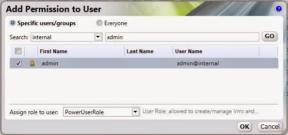
The Add Perm ission to User dialog displays. Enter a Name, or User Name, or part thereof in
the Search textbox, and click Go. A lisTof possible matches display in the results list.
Figure 4 .13. Add PowerUserRole Permission
Select the check box of the user to be assigned the permissions. Scroll through the Assign
role to user list and select PowerUserRole. Click OK.
Log in to the User Portal
Figure 4 .14 . Connect to the User Portal
Now that you have assigned PowerUserRole permissions on a virtual machine to the user named admin, you can access the virtual machine from the user portal. To log in to the user portal, all you
need is a Linux client running Mozilla Firefox or a Windows client running Internet Explorer.
If you are using a Red Hat Enterprise Linux client, install the SPICE plug-in before logging in to the User Portal. Run:
# yum install spice-xpi
To log in to the User PortalOpen your browser and navigate to https://Dmain.exam ple.com :84 4 3/UserPortal.
Substitute domain.example.com with the Red Hat Enterprise Virtualization Manager server
address.
The login screen displays. Enter your User Name and Password, and click Login.
You have now logged into the user portal. As you have PowerUserRole permissions, you are taken by
default to the Extended User Portal, where you can create and manage virtual machines in addition to
using them. This portal is ideal if you are a system administrator who has to provision multiple virtual machines for yourself or other users in your environment.
Figure 4 .15. The Extended User Portal
You can also toggle to the Basic User Portal, which is the default (and only) display for users with
UserRole permissions. This portal allows users to access and use virtual machines, and is ideal for
everyday users who do not need to make configuration changes to the system.
Figure 4 .16. The Basic User Portal
You have now completed the Quick Start Guide, and successfully set up Red Hat Enterprise
Virtualization. However, this is just the first step for you to familiarize yourself with basic Red Hat
Enterprise Virtualization operations. You can further customize your own unique environment based on your organization's needs by working with our solution architects.
Introduction
The Red Hat Enterprise Virtualization platform comprises various components which work seamlessly together, enabling the system administrator to install, configure and manage a virtualized environment. After reading this guide, you will be able to set up Red Hat Enterprise Virtualization as represented in the following diagram:
Figure 1.1. Overview of Red Hat Enterprise Virtualization components
Prerequisites
The following requirements are typical for small- to medium-sized installations. Note that the exact
requirements of the setup depend on the specific installation, sizing and load. Please use the following requirements as guidelines:
Red Hat Enterprise Virtualization Manager
- Minimum - Dual core server with 4 GB RAM, with 25 GB free disk space and 1 Gbps network
- interface.
- Recommended - Dual Sockets/Quad core server with 16 GB RAM, 50 GB free disk space on multiple disk spindles and 1 Gbps network interface.
The breakdown of the server requirements are as below:
- For the Red Hat Enterprise Linux 6 operating system: minimum 1 GB RAM and 5 GB local disk space.
- For the Manager: minimum 3 GB RAM, 3 GB local disk space and 1 Gbps network controller
- bandwidth.
- If you wish to create an ISO domain on the Manager server, you need minimum 15 GB disk space.
Note: The Red Hat Enterprise Virtualization Manager setup script, rhevm -setup, supports the
en_US.UT F-8, en_US.utf8, and en_US.utf-8 locales. Ensure that you install the Red Hat
Enterprise Virtualization Manager on a system where the locale in use is one of these
supported values.
A valid Red Hat Network subscription to the following channels:
- The Red Hat Enterprise Virtualization Manager (v.3 x86_64 ) channel, also referred to as rhel-x86_64 -server-6-rhevm -3, which provides Red Hat Enterprise Virtualization Manager.
- The JBoss Application Platform (v 5) for 6Server x86_64 channel, also referred to as jbappplatform -5-x86_64 -server-6-rpm , which provides the supported release of the application platform on which the manager runs.
- The RHEL Server Supplem entary (v. 6 64 -bit x86_64 ) channel, also referred to as rhel-x86_64 -server-supplem entary-6, which provides the supported version of the Java Runtime Environment (JRE).
A client for connecting to Red Hat Enterprise Virtualization Manager.
- Microsoft Windows (7, XP, 2003 or 2008) with Internet Explorer 7 and above
- Microsoft .NET Framework 4
For each Host (Red Hat Enterprise Virtualization Hypervisor or Red Hat Enterprise Linux)
- Minimum - Dual core server, 10 GB RAM and 10 GB Storage, 1 Gbps network interface.
- Recommended - Dual socket server, 16 GB RAM and 50 GB storage, two 1 Gbps network interfaces.
The breakdown of the server requirements are as below:
- For each host: AMD-V or Intel VT enabled, AMD64 or Intel 64 extensions, minimum 1 GB RAM, 3GB free storage and 1 Gbps network interface.
- For virtual machines running on each host: minimum 1 GB RAM per virtual machine.
- Valid Red Hat Network subscriptions for each host. You can use either Red Hat Enterprise Virtualization Hypervisor or Red Hat Enterprise Linux hosts, or both.
For each Red Hat Enterprise Virtualization Hypervisor host:
- The Red Hat Enterprise Virtualization Hypervisor (v.6 x86-64 ) channel, also referred to as rhel-x86_64 -server-6-rhevh
- For each Red Hat Enterprise Virtualization Linux host: The Red Hat Enterprise Virt Management Agent (v 6 x86_64 ) channel, also referred to as rhel-x86_64 -rhevmgm t-agent-6.
Storage and Networking- At leasTone of the supported storage types (NFS, iSCSI and FCP).
- For NFS storage, a valid IP address and export path is required.
- For iSCSI storage, a valid IP address and target information is required.
- Static IP addresses for the Red Hat Enterprise Virtualization Manager server and for each host server.
- DNS service which can resolve (forward and reverse) all the IP addresses.
- An existing DHCP server which can allocate network addresses for the virtual machines.
Virtual Machines- Installation images for creating virtual machines, depending on which operating system you wish to use.
- Microsoft Windows XP, 7, 2003 or 2008.
- Red Hat Enterprise Linux 3, 4, 5 or 6.
- Valid licenses or subscription entitlements for each operating system.
Red Hat Enterprise Virtualization User Portal- A Red Hat Enterprise Linux client running Mozilla Firefox 3.6 and higher or a Windows client running Internet Explorer 7 and higher.
Install Red Hat Enterprise Virtualization
The Red Hat Enterprise Virtualization platform consists of at leasTone Manager and one or more hosts.
Red Hat Enterprise Virtualization Manager provides a graphical user interface to manage the
physical and logical resources of the Red Hat Enterprise Virtualization infrastructure. The Manager is installed on a Red Hat Enterprise Linux 6 server, and accessed from a Windows client running
Internet Explorer.
Red Hat Enterprise Virtualization Hypervisor runs virtual machines. A physical server running
Red Hat Enterprise Linux can also be configured as a host for virtual machines on the Red Hat
Enterprise Virtualization platform.
Install Red Hat Enterprise Virtualization Manager
Figure 2.1. Install Red Hat Enterprise Virtualization Manager
The Manager is the control center of the Red Hat Enterprise Virtualization environment. It allows you to define hosts, configure data centers, add storage, define networks, create virtual machines, manage user permissions and use templates from one central location.
The Red Hat Enterprise Virtualization Manager must be installed on a server running Red Hat
Enterprise Linux 6, with minimum 4 GB RAM, 25 GB free disk space and 1 Gbps network interface.
Install Red Hat Enterprise Linux 6 on a server. When prompted for the software packages to
install, select the default Basic Server option. See the Red Hat Enterprise Linux Installation
Guide for more details.
Note: During installation, remember to set the fully qualified domain name (FQDN) and IP for the
server. If the classpathx-jaf package has been installed, it must be removed because it conflicts with some of the components required to support JBoss in Red Hat Enterprise Virtualization Manager. Run:
# yum remove classpathx-jaf
If your server has not been registered with the Red Hat Network, run:
# rhn_register
To complete registration successfully you need to supply your Red Hat Network username and
password. Follow the onscreen prompts to complete registration of the system.
After you have registered your server, update all the packages on it. Run:
# yum -y update
Reboot your server for the updates to be applied.
Subscribe the server to the required channels using the Red Hat Network web interface.
a. Log on to Red Hat Network (http://rhn.redhat.com/).
b. Click System s at the top of the page.
c. Select the system to which you are adding channels from the list presented on the screen,
by clicking the name of the system.
d. Click Alter Channel Subscriptions in the Subscribed Channels section of the
screen.
e. Select the following channels from the list presented on the screen.
Red Hat Enterprise Virtualization Manager (v.3 x86_64 )
RHEL Server Supplem entary (v. 6 64 -bit x86_64 )
JBoss Application Platform (v 5) for 6Server x86_64 (note that this
channel is listed under "Additional Services Channels for Red Hat Enterprise Linux 6 for
x86_64")
Click the Change Subscription button to finalize the change.
You are now ready to install the Red Hat Enterprise Virtualization Manager. Run the following
command:
# yum -y install rhevm
This command will download the Red Hat Enterprise Virtualization Manager installation software
and resolve all dependencies.
When the packages have finished downloading, run the installer:
# rhevm -setup
Note: rhevm -setup supports the en_US.UT F-8, en_US.utf8, and en_US.utf-8 locales.
You will not be able to run this installer on a system where the locale in use is noTone of
these supported values.The installer will take you through a series of interactive questions as listed in the following
example. If you do not enter a value when prompted, the installer uses the default settings which
are stated in [ ] brackets.
Example: Red Hat Enterprise Virtualization Manager installation
Welcom e to RHEV Manager setup utility
HTTP Port [8080] :
HTTPS Port [8443] :
Host fully qualified Dmain Name, note that this Name should be fully
resolvable [rhevm .dem o.redhat.com ] :
Password for Adm inistrator (adm in@ internal) :
Database password (required for secure authentication with the locally
created database) :
Confirm password :
Organization Name for the Certificate: Red Hat
The default storage type you will be using ['NFS'| 'FC'| 'ISCSI'] [NFS] :
ISCSI
Should the installer configure NFS share on this server to be used as an ISO
Dmain? ['yes'| 'no'] [no] : yes
Mount point path: /data/iso
Display Name for the ISO Dmain: local-iso-share
Firewall ports need to be opened.
You can let the installer configure iptables autom atically overriding the current configuration. The old configuration will be backed up.
Alternately you can configure the firewall later using an example iptables file found under /usr/share/rhevm /conf/iptables.example
Configure iptables ? ['yes'| 'no']: yesImportant points to note:- The default ports 8080 and 84 4 3 must be available to access the manager on HTTP and HTTPS respectively.
- If you elect to configure an NFS share it will be exported from the machine on which the manager is being installed.
- The storage type that you select will be used to create a data center and cluster. You will then be able to attach storage to these from the Administration Portal.
You are then presented with a summary of the configurations you have selected. Type yes to
accept them.
Example: Confirm Manager installation settings
RHEV Manager will be installed using the following configuration:
=================================================================
http-port: 8080
https-port: 8443
host-fqdn: rhevm .dem o.redhat.com
auth-pass: * * * * * * * *
db-pass: * * * * * * * *
org-Name: Red Hat
default-dc-type: ISCSI
nfs-m p: /data/iso
iso-Dmain-Name: local-iso-share
override-iptables: yes
Proceed with the configuration listed above? (yes|no): yes The installation commences. The following message displays, indicating that the installation was
successful.
Example: Successful installation
Installing:
Creating JBoss Profile... [ DONE ]
Creating CA... [ DONE ]
Setting Database Security... [ DONE ]
Creating Database... [ DONE ]
Updating the Default Data Center Storage Type... [ DONE ]
Editing JBoss Configuration... [ DONE ]
Editing RHEV Manager Configuration... [ DONE ]
Configuring the Default ISO Dmain... [ DONE ]
Starting JBoss Service... [ DONE ]
Configuring Firewall (iptables)... [ DONE ]
* * * * Installation com pleted successfully * * * * * *Your Red Hat Enterprise Virtualization Manager is now up and running. You can log in to the Red Hat Enterprise Virtualization Manager's web administration portal with the username adm in (the
administrative user configured during installation) in the internal domain. Instructions to do so are
provided at the end of this chapter.
Important: The internal domain is automatically created upon installation, however no new users can be added to this domain. To authenticate new users, you need an external directory service. Red Hat
Enterprise Virtualization supports IPA and Active Directory, and provides a utility called rhevmmanage-domains to attach new directories to the system.Install Hosts
Figure 2.2. Install Red Hat Enterprise Virtualization Hosts
After you have installed the Red Hat Enterprise Virtualization Manager, install the hosts to run your
virtual machines. In Red Hat Enterprise Virtualization, you can use either Red Hat Enterprise
Virtualization Hypervisor or Red Hat Enterprise Linux as hosts.
Install Red Hat Enterprise Virtualization Hypervisor
This document provides instructions for installing the Red Hat Enterprise Virtualization Hypervisor using a CD. For alternative methods including PXE networks or USB devices, see the Red Hat Enterprise Linux Hypervisor Deployment Guide.
Before installing the Red Hat Enterprise Virtualization Hypervisor, you need to download the hypervisor image from the Red Hat Network and create a bootable CD with the image. This procedure can be performed on any machine running Red Hat Enterprise Linux.
To prepare a Red Hat Enterprise Virtualization Hypervisor installation CD- Download the latest version of the rhev-hypervisor* package from Red Hat Network. The lisTof hypervisor packages is located at the Red Hat Enterprise Virtualization Hypervisor
(v.6 x86_64 ) channel.
a. Log on to Red Hat Network (http://rhn.redhat.com/).
b. Click System s at the top of the page.
c. From the list presented on the screen, select the system on which the Red Hat Enterprise
Virtualization Manager is installed by clicking on its name.
d. Click Alter Channel Subscriptions in the Subscribed Channels section of the screen.
e. Select the Red Hat Enterprise Virtualization Hypervisor (v.6 x86_64 ) channel from the list presented on the screen, then click the Change Subscription button to finalize the change.
Log in to the system on which the Red Hat Enterprise Virtualization Manager is installed. You must log in as the root user to install the rhev-hypervisor package. Run the following command:
# yum install "rhev-hypervisor* "
The hypervisor ISO image is installed into the /usr/share/rhev-hypervisor/ directory.Insert a blank CD into your CD writer. Use the cdrecord utility to burn the hypervisor ISO image
onto your disc. Run:
# cdrecord dev=/dev/cdrw /usr/share/rhev-hypervisor/rhev-hypervisor.iso
You have created a Red Hat Enterprise Virtualization Hypervisor installation CD, now you can use it to boot the machine designated as your hypervisor host. For this guide you will use the interactive installation where you are prompted to configure your settings in a graphical interface. Use the following keys to navigate around the installation screen:
Menu Navigation Keys
Use the Up and Down arrow keys to navigate between selections. Your selections are highlighted in white.
The T ab key allows you to move between fields.
Use the Spacebar to tick checkboxes, represented by [ ] brackets. A marked checkbox displays
with an asterisk (* ).
To proceed with the selected configurations, press the Enter key.
To configure Red Hat Enterprise Virtualization Hypervisor installation settings
Insert the Red Hat Enterprise Virtualization Hypervisor 6.2-3.0 installation CD into your CD-ROM
drive and reboot the machine. When the boot splash screen displays, press the T ab key and
select Boot to boot from the hypervisor installation media. Press Enter.
On the installation confirmation screen, select Install RHEV Hypervisor and press Enter.
The installer automatically detects the drives attached to the system. The selected disk for
booting the hypervisor is highlighted in white. Ensure that the local disk is highlighted, otherwise
use the arrow keys to select the correct disk. Select Continue and press Enter.
You are prompted to confirm your selection of the local drive, which is marked with an asterisk.
Select Continue and press Enter.
Enter a password for local console access and confirm it. Select Install and press Enter. The
Red Hat Enterprise Virtualization Hypervisor partitions the local drive, then commences
installation.
Once installation is complete, a dialog prompts you to Reboot the hypervisor. Press Enter to
confirm. Remove the installation disc.
After the hypervisor has rebooted, you will be taken to a login shell. Log in as the adm in user with
the password you provided during installation to enter the Red Hat Enterprise Virtualization
Hypervisor management console.
On the hypervisor management console, there are eight tabs on the left. Press the Up and Down
keys to navigate between the tabs and Enter to access them.
Select the Network tab. Configure the following options:
HostName: Enter the hostname in the formaTof hostName.Dmain.example.com .
DNS Server: Enter the Domain Name Server address in the formaTof 192.168.0.254 . You can use up to two DNS servers.
NTP Server: Enter the Network T ime Protocol server address in the formaTof rhel.pool.ntp.org. This synchronizes the hypervisor's system clock with thaTof the manager's. You can use up to two NTP servers. Select Apply and press Enter to save your network settings.
The installer automatically detects the available network interface devices to be used as the management network. Select the device and press Enter to access the interface configuration menu. Under IPv4 Settings, tick either the DHCP or Static checkbox.
If you are using static IPv4 network configuration, fill in the IP Address, Netm ask and Gateway fields.
To confirm your network settings, selecToK and press Enter.
Select the RHEV-M tab. Configure the following options:
Managem ent Server: Enter the Red Hat Enterprise Virtualization Manager domain name in the formaTof rhevm .dem o.redhat.com.
Management Server Port: Enter the management server port number. The default is 8443.
Connect to the RHEV Manager and Validate Certificate: Tick this checkbox if you wish to verify the RHEVM security certificate.
Set RHEV-M Adm in Password: This field allows you to specify the root password for the hypervisor, and enable SSH password authentication from the Red Hat Enterprise Virtualization Manager.
Select Apply and press Enter. A dialog displays, asking you to connect the hypervisor to the Red Hat Enterprise Virtualization Manager and validate its certificate. Select Approve and press Enter. A message will display notifying you that the manager configuration has been successfully updated.
Under the Red Hat Network tab, you can register the host with the Red Hat Network.
This enables the host to run Red Hat Enterprise Linux virtual machines with proper RHN entitlements. Configure the following settings:
Enter your Red Hat Network credentials in the Login and Password fields.
To select the method by which the hypervisor receives updates, tick either the RHN or Satellite checkboxes. Fill in the RHN URL and RHN CA fields.
To confirm your RHN settings, select Apply and press Enter.
Accept all other default settings. For information on configuring security, logging, kdump and
remote storage
Finally, select the Status tab. Select Restart and press Enter to reboot the host and
apply all changes.
You have now successfully installed the Red Hat Enterprise Virtualization Hypervisor. Repeat this
procedure if you wish to use more hypervisors. The following sections will provide instructions on how to approve the hypervisors for use with the Red Hat Enterprise Virtualization Manager.
Install Red Hat Enterprise Linux Host
You now know how to install a Red Hat Enterprise Virtualization Hypervisor. In addition to hypervisor hosts, you can also reconfigure servers which are running Red Hat Enterprise Linux to be used as virtual machine hosts.
To install a Red Hat Enterprise Linux 6 host
On the machine designated as your Red Hat Enterprise Linux host, install Red Hat Enterprise
Linux 6.2. SelecTonly the Base package group during installation.
If your server has not been registered with the Red Hat Network, run the rhn_register command as root to register it. To complete registration successfully you will need to supply your Red Hat Network username and password. Follow the onscreen prompts to complete registration of the system.
# rhn_register
Subscribe the server to the required channels using the Red Hat Network web interface.
Log on to Red Hat Network (http://rhn.redhat.com/).
b. Click System s at the top of the page.
c. Select the system to which you are adding channels from the list presented on the screen,
by clicking the name of the system.
d. Click Alter Channel Subscriptions in the Subscribed Channels section of the
screen.
e. Select the Red Hat Enterprise Virt Managem ent Agent (v 6 x86_64 ) channel
from the list presented on the screen, then click the Change Subscription button to
finalize the change.
Red Hat Enterprise Virtualization platform uses a number of network ports for management and
other virtualization features. Adjust your Red Hat Enterprise Linux host's firewall settings to allow
access to the required ports by configuring iptables rules. Modify the /etc/sysconfig/iptables file so it resembles the following example:
:INPUT ACCEPT [0:0]
:FORWARD ACCEPT [0:0]
:OUTPUT ACCEPT [10765:598664]
-A INPUT -m state --state RELATED,ESTABLISHED -j ACCEPT
-A INPUT -p icm p -j ACCEPT
-A INPUT -i lo -j ACCEPT
-A INPUT -p tcp --dport 22 -j ACCEPT
-A INPUT -p tcp --dport 16514 -j ACCEPT
-A INPUT -p tcp --dport 54321 -j ACCEPT
-A INPUT -p tcp -m m ultiport --dports 5634:6166 -j ACCEPT
-A INPUT -p tcp -m m ultiport --dports 49152:49216 -j ACCEPT
-A INPUT -p tcp -m state --state NEW
-A INPUT -j REJECT --reject-with icm p-host-prohibited
-A FORWARD -m physdev ! --physdev-is-bridged -j REJECT --reject-with icm phost-
prohibited
COMMIT
Ensure that the iptables service is configured to starTon boot and has been restarted, or started for the first time if it was not already running. Run the following commands:
# chkconfig iptables on
# service iptables restart
You have now successfully installed a Red Hat Enterprise Linux host. As before, repeat this procedure if you wish to use more Linux hosts. Before you can start running virtual machines on your host, you have to manually add it to the Red Hat Enterprise Virtualization Manager via the administration portal, which you will access in the next step.
Figure 2.3. Connect to the Manager administration portal
Now that you have installed the Red Hat Enterprise Virtualization Manager and hosts, you can log in to the Manager administration portal to start configuring your virtualization environment. The web-based administration portal can be accessed using a Windows client running Internet Explorer.
Before logging in, install .NET Framework 4 and modify the default security settings on the machine used to access the web administration portal. The example below is applicable for Windows 2008.
To configure Windows client to access the administration portal
To install .NET Framework 4, download it from
http://www.microsoft.com/download/en/details.aspx?id=17718. Run this executable as a user with administration access to the system.
Next, disable Internet Explorer Enhanced Security Configuration. Click Start → Administrative
Tools → Server Manager. On the Security Inform ation pane in the Server Manager window, click Configure IE ESC. SelecToff for Administrators and Users to disable the security configuration. Click OK.
To add the administration portal to the browser's lisTof trusted sites, open a browser and click on
Tools → InterneToptions. Click on the Security tab.
Select Trusted Sites. Click Sites to display the T rusted Sites dialog. Enter the URL for your administration portal in the Add this website to the zone textbox. Click Add, then Close.
Click the Custom Level... button. Locate the XAML browser applications item in the list, ensure that it is set to Enable, then click OK.
Restart Internet Explorer to access the administration portal.
Log In to Administration Portal
Now that the prerequisites have been resolved, you can log in to the Red Hat Enterprise Virtualization
Manager administration portal. Ensure that you have the administrator password configured during
installation as instructed in Example, “Red Hat Enterprise Virtualization Manager installation”.
To connect to Red Hat Enterprise Virtualization web management portal
Open a browser and navigate to https://Dmain.exam ple.com :84 4 3/RHEVManager.
Substitute Dmain.exam ple.com with the URL provided during installation.
If this is your first time connecting to the administration portal, Red Hat Enterprise Virtualization
Manager will issue security certificates for your browser. Click the link labelled this certificate to trust the ca.cer certificate. A pop-up displays, click Open to launch the Certificate dialog. Click Install Certificate and select to place the certificate in Trusted Root Certification Authorities store.
Back on the browser screen, click the link labelled here and follow the prompts to install the RHEV-GUI-CertificateInstaller executable. A pop-up displays again, this time click Run.
Note that the actual certificate installation is preceded by an ActiveX installation.
When complete, a new link labelled here appears. Click on it to reload the administration portal.
The portal login screen displays. Enter adm in as your User Name, and enter the Password
that you provided during installation. Ensure that your domain is set to Internal. Click Login.
You have now successfully logged in to the Red Hat Enterprise Virtualization web administration portal. Here, you can configure and manage all your virtual resources. The functions of the Red Hat Enterprise Virtualization Manager graphical user interface are described in the following figure and list:
Figure 2.4 . Administration Portal Features
Header: This bar contains the name of the logged in user, the sign out button, the option to
configure user roles.
Navigation Pane: This pane allows you to navigate between the Tree, Bookmarks and Tags tabs. In the Tree tab, tree mode allows you to see the entire system tree and provides a visual representation your virtualization environment's architecture.
Resources Tabs: These tabs allow you to access the resources of Red Hat Enterprise Virtualization. You should already have a Default Data Center, a Default Cluster, a Host waiting to be approved, and available Storage waiting to be attached to the data center.
Results List: When you select a tab, this list displays the available resources. You can perform
a task on an individual item or multiple items by selecting the item(s) and then clicking the relevant
action button. If an action is not possible, the button is disabled.
Details Pane: When you select a resource, this pane displays its details in several subtabs.
These subtabs also contain action buttons which you can use to make changes to the selected
resource.
Once you are familiar with the layouTof the administration portal, you can start configuring your virtual environment.
Configure Red Hat Enterprise Virtualization
Now that you have logged in to the administration portal, configure your Red Hat Enterprise Virtualization environment by defining the data center, host cluster, networks and storage. Even though this guide makes use of the default resources configured during installation, if you are setting up a Red Hat Enterprise Virtualization environment with completely new components, you should perform the configuration procedure in the sequence given here.
Configure Data Centers
Figure 3.1. Configure Data Center
A data center is a logical entity that defines the seTof physical and logical resources used in a managed virtual environment. Think of it as a container which houses clusters of hosts, virtual machines, storage and networks.
By default, Red Hat Enterprise Virtualization creates a data center at installation. Its type is configured from the installation script. To access it, navigate to the Tree pane, click Expand All, and select the Default data center. On the Data Centers tab, the Default data center displays.
Figure 3.2. Data Centers Tab
The Default data center is used for this document, however if you wish to create a new data center
see the Red Hat Enterprise Virtualization Administration Guide.
Configure Cluster
Figure 3.3. Populate Cluster with Hosts
A cluster is a seTof physical hosts that are treated as a resource pool for a seTof virtual machines.
Hosts in a cluster share the same network infrastructure, the same storage and the same type of CPU.
They constitute a migration domain within which virtual machines can be moved from host to host.
By default, Red Hat Enterprise Virtualization creates a cluster at installation.
To access it, navigate to the Tree pane, click Expand All and select the Default cluster. On the Clusters tab, the Default
Figure 3.4 . Clusters Tab
For this document, the Red Hat Enterprise Virtualization Hypervisor and Red Hat Enterprise Linux hosts will be attached to the Default host cluster. If you wish to create new clusters, or live migrate virtual machines between hosts in a cluster, see the Red Hat Enterprise Virtualization Evaluation Guide.
Configure Networking
Figure 3.5. Configure Networking
At installation, Red Hat Enterprise Virtualization defines a Management network for the default data center. This network is used for communication between the manager and the host. New logical networks - for example for guest data, storage or display - can be added to enhance network speed and performance. All networks used by hosts and clusters must be added to data center they belong to.
To access the Management network, click on the Clusters tab and select the default cluster. Click the Logical Networks tab in the Details pane. The rhevm network displays.
Figure 3.6. Logical Networks Tab
The rhevm Management network is used for this document, however if you wish to create new logical networks see the Red Hat Enterprise Virtualization Administration Guide.
Configure Hosts
Figure 3.7. Configure Hosts
You have already installed your Red Hat Enterprise Virtualization Hypervisor and Red Hat Enterprise
Linux hosts, but before they can be used, they have to be added to the Manager. The Red Hat
Enterprise Virtualization Hypervisor is specifically designed for the Red Hat Enterprise Virtualization
platform, therefore iTonly needs a simple click of approval. Conversely, Red Hat Enterprise Linux is a general purpose operating system, therefore reprogramming it as a host requires additional
configuration.
Approve Red Hat Enterprise Virtualization Hypervisor Host
The Hypervisor you installed in Section “Install Red Hat Enterprise Virtualization Hypervisor” is automatically registered with the Red Hat Enterprise Virtualization platform. It displays in the Red Hat Enterprise Virtualization Manager, and needs to be approved for use.
To set up a Red Hat Enterprise Virtualization Hypervisor hostOn the Tree pane, click Expand All and select Hosts under the Default cluster. On the Hosts tab, select the name of your newly installed hypervisor.
Figure 3.8. Red Hat Enterprise Virtualization Hypervisor pending approval
Click the Approve button. The Edit and Approve Host dialog displays. Accept the defaults
or make changes as necessary, then click OK.
Figure 3.9. Approve Red Hat Enterprise Virtualization Hypervisor
The host status will change from Non Operational to Up.
Attach Red Hat Enterprise Linux Host
In contrast to the hypervisor host, the Red Hat Enterprise Linux host you installed in Section,
“Install Red Hat Enterprise Linux Host” is not automatically detected. It has to be manually attached to the Red Hat Enterprise Virtualization platform before it can be used.
To attach a Red Hat Enterprise Linux hostOn the Tree pane, click Expand All and select Hosts under the Default cluster. On the Hosts
tab, click New.
The New Host dialog displays.
Figure 3.10. Attach Red Hat Enterprise Linux Host
Enter the details in the following fields:
- Data Center: the data center to which the host belongs. Select the Default data center.
- Host Cluster: the cluster to which the host belongs. Select the Default cluster.
- Name: a descriptive name for the host.
- Address: the IP address, or resolvable hostname of the host, which was provided during installation.
- Root Password: the password of the designated host; used during installation of the host.
- Configure iptables rules: This checkbox allows you to override the firewall settings on the host with the default rules for Red Hat Enterprise Virtualization.
If you wish to configure this host for OuTof Band (OOB) power management, select the Power Managem ent tab. T ick the Enable Power Managem ent checkbox and provide the required information in the following fields:
- Address: The address of the host.
- User Name: A valid user name for the OOB management.
- Password: A valid, robust password for the OOB management.
- Type: The type of OOB management device. Select the appropriate device from the drop down list.
alom Sun Advanced Lights Out Manager
apc American Power Conversion Master
MasterSwitch network power switch
bladecenter IBM Bladecentre Remote Supervisor Adapter
drac5 Dell Remote Access Controller for Dell
computers
eps ePowerSwitch 8M+ network power switch
ilo HP Integrated Lights Out standard
ilo3 HP Integrated Lights Out 3 standardipmilan Intelligent Platform Management Interface
rsa IBM Remote Supervisor Adaptor
rsb Fujitsu-Siemens RSB management interface
wti Western T elematic Inc Network PowerSwitch
cisco_ucs Cisco Unified Computing System Integrated
Management Controller - Options: Extra command line options for the fence agent. Detailed documentation of the options available is provided in the man page for each fence agent.
Click the Test button to test the operation of the OOB management solution.
If you do not wish to configure power management, leave the Enable Power Management checkbox unmarked.
Click OK. If you have not configured power management, a pop-up window prompts you to confirm if you wish to proceed without power management. SelecToK to continue.
The new host displays in the lisTof hosts with a status of Installing. Once installation is complete, the status will update to Reboot and then Awaiting. When the host is ready for use, its status changes to Up.
You have now successfully configured your hosts to run virtual machines. The next step is to prepare data storage domains to house virtual machine disk images.
Configure Storage
Figure 3.11. Configure Storage
After configuring your logical networks, you need to add storage to your data center.
Red Hat Enterprise Virtualization uses a centralized shared storage system for virtual machine disk
images and snapshots. Storage can be implemented using Network File System (NFS), Internet Small
Computer System Interface (iSCSI) or Fibre Channel Protocol (FCP). Storage definition, type and function, are encapsulated in a logical entity called a Storage Dmain. Multiple storage domains are
supported.
For this guide you will use two types of storage domains. The first is an NFS share for ISO images of installation media. You have already created this ISO domain during the Red Hat Enterprise Virtualization Manager installation
The second storage domain will be used to hold virtual machine disk images. For this domain, you need at leasTone of the supported storage types. You have already set a default storage type during
installation as described in Section, “Install Red Hat Enterprise Virtualization Manager”. Ensure that you use the same type when creating your data domain.
Select your next step by checking the storage type you should use:- Navigate to the Tree pane and click the Expand All button. Under System, click Default. On
the results list, the Default data center displays. - On the results list, the Storage Type column displays the type you should add.
- Now that you have verified the storage type, create the storage domain:
For NFS storage, refer to Section, “Create an NFS Data Domain”.
For iSCSI storage, refer to Section, “Create an iSCSI Data Domain”.
For FCP storage, refer to Section, “Create an FCP Data Domain”.
Create an NFS Data Domain
Because you have selected NFS as your default storage type during the Manager installation, you will
now create an NFS storage domain. An NFS type storage domain is a mounted NFS share that is
attached to a data center and used to provide storage for virtual machine disk images.
To add NFS storage:Navigate to the Tree pane and click the Expand All button. Under System, select the Default
data center and click on Storage. The available storage domains display on the results list. Click
New Domain.
The New Storage dialog box displays.
Figure 3.12. Add New Storage
Configure the following options:
- Name: Enter a suitably descriptive name.
- Data Center: The Default data center is already pre-selected.
- Dmain Function / Storage Type: In the drop down menu, select Data → NFS. The storage domain types not compatible with the Default data center are grayed out. After you select your domain type, the Export Path field appears.
- Use Host: Select any of the hosts from the drop down menu. Only hosts which belong in the pre-selected data center will display in this list.
- Export path: Enter the IP address or a resolvable hostname of the chosen host. The export path should be in the formaTof 192.168.0.10:/data or domain.example.com :/data
Click OK. The new NFS data domain displays on the Storage tab. It will remain with a Locked status while it is being prepared for use. When ready, it is automatically attached to the data center.
You have created an NFS storage domain. Now, you need to attach an ISO domain to the data center
and upload installation images so you can use them to create virtual machines. Proceed to Section, “Attach and Populate ISO domain”.
Create an iSCSI Data Domain
Because you have selected iSCSI as your default storage type during the Manager installation, you will now create an iSCSI storage domain. Red Hat Enterprise Virtualization platform supports iSCSI storage domains spanning multiple pre-defined Logical Unit Numbers (LUNs).
To add iSCSI storage:
On the side pane, select the Tree tab. On System , click the + icon to display the available data
centers.
Double click on the Default data center and click on Storage. The available storage domains
display on the results list. Click New Domain.
The New Dmain dialog box displays.
Figure 3.13. Add iSCSI Storage
Configure the following options:
- Name: Enter a suitably descriptive name.
- Data Center: The Default data center is already pre-selected.
- Domain Function / Storage Type: In the drop down menu, select Data → iSCSI.
- The storage domain types which are not compatible with the Default data center are grayed out. After you select your domain type, the Use Host and Discover T argets fields display.
- Use host: Select any of the hosts from the drop down menu. Only hosts which belong in this data center will display in this list.
To connect to the iSCSI target, click the Discover Targets bar. This expands the menu to
display further connection information fields.
Figure 3.14 . Attach LUNs to iSCSI domain
Enter the required information:
- Address: Enter the address of the iSCSI target.
- Port: Select the port to connect to. The default is 3260.
- User Authentication: If required, enter the username and password.
Click the Discover button to find the targets. The iSCSI targets display in the results list with a
Login button for each target.
Click Login to display the lisTof existing LUNs. Tick the Add LUN checkbox to use the selected
LUN as the iSCSI data domain.
Click OK. The new NFS data domain displays on the Storage tab. It will remain with a Locked
status while it is being prepared for use. When ready, it is automatically attached to the data
center.
You have created an iSCSI storage domain. Now, you need to attach an ISO domain to the data center
and upload installation images so you can use them to create virtual machines. Proceed to Section ,“Attach and Populate ISO domain”.
Create an FCP Data Domain
Because you have selected FCP as your default storage type during the Manager installation, you will
now create an FCP storage domain. Red Hat Enterprise Virtualization platform supports FCP storage domains spanning multiple pre-defined Logical Unit Numbers (LUNs).
To add FCP storage:
On the side pane, select the Tree tab. On System , click the + icon to display the available data
centers.
Double click on the Default data center and click on Storage. The available storage domains
display on the results list. Click New Domain.
The New Dmain dialog box displays.
Figure 3.15. Add FCP Storage
Configure the following options:
- Name: Enter a suitably descriptive name.
- Data Center: The Default data center is already pre-selected.
- Domain Function / Storage Type: Select FCP.
- Use Host: Select the IP address of either the hypervisor or Red Hat Enterprise Linux host.
- The lisTof existing LUNs display. On the selected LUN, tick the Add LUN checkbox to use it as the FCP data domain.
Click OK. The new FCP data domain displays on the Storage tab. It will remain with a Locked
status while it is being prepared for use. When ready, it is automatically attached to the data
center.
You have created an FCP storage domain. Now, you need to attach an ISO domain to the data center
and upload installation images so you can use them to create virtual machines. Proceed to Section, “Attach and Populate ISO domain”.
Attach and Populate ISO domain
You have defined your first storage domain to store virtual guest data, now it is time to configure your second storage domain, which will be used to store installation images for creating virtual machines. You have already created a local ISO domain during the installation of the Red Hat Enterprise Virtualization Manager. To use this ISO domain, attach it to a data center.
To attach the ISO domainNavigate to the Tree pane and click the Expand All button. Click Default. On the results list,
the Default data center displays.
On the details pane, select the Storage tab and click the Attach ISO button.
The Attach ISO Library dialog appears with the available ISO domain. Select it and click OK.
Figure 3.16. Attach ISO Library
The ISO domain appears in the results lisTof the Storage tab. It displays with the Locked status
as the domain is being validated, then changes to Inactive.
Select the ISO domain and click the Activate button. The status changes to Locked and then to
Active.
Media images (CD-ROM or DVD-ROM in the form of ISO images) must be available in the ISO repository for the virtual machines to use. To do so, Red Hat Enterprise Virtualization provides a utility that copies the images and sets the appropriate permissions on the file. The file provided to the utility and the ISO share have to be accessible from the Red Hat Enterprise Virtualization Manager.
Log in to the Red Hat Enterprise Virtualization Manager server console to upload images to the ISO
domain.
To upload ISO imagesCreate or acquire the appropriate ISO images from boot media. Ensure the path to these images
is accessible from the Red Hat Enterprise Virtualization Manager server.
The next step is to upload these files. First, determine the available ISO domains by running:
# rhevm -iso-uploader list
You will be prompted to provide the admin user password which you use to connect to the
administration portal. The tool lists the name of the ISO domain that you attached in the previous
section.
ISO Storage Dmain List:
local-iso-share
Now you have all the information required to upload the required files. On the Manager console,
copy your installation images to the ISO domain. For your images, run:
# rhevm -iso-uploader upload -i local-iso-share [file1] [file2] .... [fileN]
You will be prompted for the admin user password again, provide it and press Enter.
Note that the uploading process can be time consuming, depending on your storage performance.
After the images have been uploaded, check that they are available for use in the Manager
administration portal.
- Navigate to the Tree and click the Expand All button.
- Under Storage, click on the name of the ISO domain. It displays in the results list. Click on it to display its details pane.
- On the details pane, select the Im ages tab. The lisTof available images should be populated with the files which you have uploaded. In addition, the RHEV-toolsSetup.iso and virtio-win.vfd images should have been automatically uploaded during installation.
Figure 3.17. Uploaded ISO images
Now that you have successfully prepared the ISO domain for use, you are ready to start creating virtual machines.
Manage Virtual Machines
The final stage of setting up Red Hat Enterprise Virtualization is the virtual machine lifecycle - spanning the creation, deployment and maintenance of virtual machines; using templates; and configuring user permissions. This chapter will also show you how to log in to the user portal and connect to virtual machines.
Create Virtual Machines Figure 4 .1. Create Virtual Machines
On Red Hat Enterprise Virtualization, you can create virtual machines from an existing template, as a
clone, or from scratch. Once created, virtual machines can be booted using ISO images, a network boot (PXE) server, or a hard disk. This document provides instructions for creating a virtual machine using an ISO image.
In your current configuration, you should have at leasTone host available for running virtual machines, and uploaded the required installation images to your ISO domain. This section guides you through the creation of a Red Hat Enterprise Linux 6 virtual server. You will perform a normal attended installation using a virtual DVD.
To create a Red Hat Enterprise Linux serverNavigate to the Tree pane and click Expand All. Click the VMs icon under the Default cluster.
On the Virtual Machines tab, click New Server.
Figure 4 .2. Create New Linux Virtual Machine
You only need to fill in the Name field and select Red Hat Enterprise Linux 6.x as your
Operating System . You may alter other settings but in this example we will retain the defaults.
Click OK to create the virtual machine.
A New Virtual Machine - Guide Me window opens. This allows you to add networks and
storage disks to the virtual machine.
Figure 4 .3. Create Virtual Machines
Click Configure Network Interfaces to define networks for your virtual machine. The parameters in the following figure are recommended, but can be edited as necessary. When you have configured your required settings, click OK.
Figure 4 .4 . New Network Interface configurations
You are returned to the Guide Me window. This time, click Configure Virtual Disks to add
storage to the virtual machine. The parameters in the following figure are recommended, but can
be edited as necessary. When you have configured your required settings, click OK.
Figure 4 .5. New Virtual Disk configurations
Close the Guide Me window by clicking Configure Later. Your new RHEL 6 virtual machine will
display in the Virtual Machines tab.
You have now created your first Red Hat Enterprise Linux virtual machine. Before you can use your
virtual machine, install an operating system on it.
To install the Red Hat Enterprise Linux guesToperating system
Right click the virtual machine and select Run Once. Configure the following options:
Figure 4 .6. Run Red Hat Enterprise Linux Virtual Machine
- Attach CD: Red Hat Enterprise Linux 6
- Boot Sequence: CD-ROM
- Display protocol: SPICE
Retain the default settings for the other options and click OK to start the virtual machine.
Select the virtual machine and click the Console icon. As this is your first time connecting to
the virtual machine, allow the installation of the Spice Active X and the SPICE client.
After the SPICE plugins have been installed, select the virtual machine and click the Console icon
again. This displays a window to the virtual machine, where you will be prompted to begin installing the operating system.
After the installation has completed, shut down the virtual machine and reboot from the hard drive.
You can now connect to your Red Hat Enterprise Linux virtual machine and start using it.
Create a Windows Virtual Machine
You now know how to create a Red Hat Enterprise Linux virtual machine from scratch. The procedure of creating a Windows virtual machine is similar, except that it requires additional virtio drivers. This example uses Windows 7, but you can also use other Windows operating systems. You will perform a normal attended installation using a virtual DVD.
To create a Windows desktopNavigate to the Tree pane and click Expand All. Click the VMs icon under the Default cluster.
On the Virtual Machines tab, click New Desktop.
Figure 4 .7. Create New Windows Virtual Machine
You only need to fill in the Name field and select Windows 7 as your Operating System . You
may alter other settings but in this example we will retain the defaults. Click OK to create the virtual
machine.
A New Virtual Machine - Guide Me window opens. This allows you to define networks for
the virtual machine. Click Configure Network Interfaces. See Figure 4.4, “New Network
Interface configurations” for details.
You are returned to the Guide Me window. This time, click Configure Virtual Disks to add
storage to the virtual machine. See Figure 4.5, “New Virtual Disk configurations” for details.
Close the Guide Me windows. Your new Windows 7 virtual machine will display in the Virtual
Machines tab.
To install Windows guesToperating systemRight click the virtual machine and select Run Once. The Run Once dialog displays as in
Figure 4.6, “Run Red Hat Enterprise Linux Virtual Machine”. Configure the following options:
- Attach Floppy: virtio-win
- Attach CD: Windows 7
- Boot sequence: CD-ROM
- Display protocol: SPICE
Retain the default settings for the other options and click OK to start the virtual machine.
Select the virtual machine and click the Console icon. This displays a window to the virtual
machine, where you will be prompted to begin installing the operating system.
Accept the default settings and enter the required information as necessary. The only change you must make is to manually install the VirtIO drivers from the virtual floppy disk (vfd) image. To do so, select the Custom (advanced) installation option and click Load Driver. Press Ctrl and select:
- Red Hat VirtIO Ethernet Adapter
- Red Hat VirtIO SCSI Controller
The installation process commences, and the system will reboot itself several times.
Back on the administration portal, when the virtual machine's status changes back to Up, right click on it and select Change CD. From the lisTof images, select RHEV-toolsSetup to attach the Guest Tools ISO which provides features including USB redirection and SPICE display optimization.
Click Console and log in to the virtual machine. Locate the CD drive to access the contents of the Guest Tools ISO, and launch the RHEV-toolsSetup executable. After the tools have been installed, you will be prompted to restart the machine for changes to be applied.
You can now connect to your Windows virtual machine and start using it.
Using Templates
Figure 4 .8. Create Templates
Now that you know how to create a virtual machine, you can save its settings into a template. This template will retain the original virtual machine's configurations, including virtual disk and network interface settings, operating systems and applications. You can use this template to rapidly create replicas of the original virtual machine.
Create a Red Hat Enterprise Linux Template
To make a Red Hat Enterprise Linux virtual machine template, use the virtual machine you created in Section, “Create a Red Hat Enterprise Linux Virtual Machine” as a basis. Before it can be used, it has to be sealed. This ensures that machine-specific settings are not propagated through the template.
To prepare a Red Hat Enterprise Linux virtual machine for use as a templateConnect to the Red Hat Enterprise Linux virtual machine to be used as a template. Flag the
system for re-configuration by running the following command as root:
# touch /.unconfigured
Remove ssh host keys. Run:
# rm -rf /etc/ssh/ssh_host_*
Shut down the virtual machine. Run:
# poweroff
The virtual machine has now been sealed, and is ready to be used as a template for Linux virtual
machines.
To create a template from a Red Hat Enterprise Linux virtual machineIn the administration portal, click the Virtual Machines tab. Select the sealed Red Hat
Enterprise Linux 6 virtual machine. Ensure that it has a status of Down.
Click Make Template. The New Virtual Machine Template displays.
Click Make Template. The New Virtual Machine Template displays.
Figure 4 .9. Make new virtual machine template
Enter information into the following fields:
- Name: Name of the new template
- Description: Description of the new template
- Host Cluster: The Host Cluster for the virtual machines using this template.
- Make Private: If you tick this checkbox, the template will only be available to the template's creator and the administrative user. Nobody else can use this template unless they are given permissions by the existing permitted users.
Click OK. The virtual machine displays a status of "Image Locked" while the template is being
created. The template is created and added to the Templates tab. During this time, the action
buttons for the template remain disabled. Once created, the action buttons are enabled and the
template is ready for use.
Clone a Red Hat Enterprise Linux Virtual Machine
In the previous section, you created a Red Hat Enterprise Linux template complete with pre-configured storage, networking and operating system settings. Now, you will use this template to deploy a preinstalled virtual machine.
To clone a Red Hat Enterprise Linux virtual machine from a templateNavigate to the Tree pane and click Expand All. Click the VMs icon under the Default cluster.
On the Virtual Machines tab, click New Server.
Figure 4 .10. Create virtual machine based on Linux template
On the General tab, select the existing Linux template from the Based on Template
list.
Enter a suitable Name and appropriate Description, then accept the default values
inherited from the template in the resTof the fields. You can change them if needed.
Click the Resource Allocation tab. On the Provisioning field, click the drop down
menu and select the Clone option.
Figure 4 .11. Set the provisioning to Clone
Retain all other default settings and click OK to create the virtual machine. The virtual machine
displays in the Virtual Machines list.
Create a Windows Template
To make a Windows virtual machine template, use the virtual machine you created in Section,
“Create a Windows Virtual Machine” as a basis.
Before a template for Windows virtual machines can be created, it has to be sealed with sysprep. This ensures that machine-specific settings are not propagated through the template.
Note that the procedure below is applicable for creating Windows 7 and Windows 2008 R2 templates.
To seal a Windows virtual machine with sysprepIn the Windows virtual machine to be used as a template, open a command line terminal and type
regedit.
The Registry Editor window displays. On the left pane, expand HKEY_LOCAL_MACHINE →
SYSTEM → SETUP.
On the main window, right click to add a new string value using New → String Value. Right click
on the file and select Modify. When the Edit String dialog box displays, enter the following
information in the provided text boxes:
- Value name: UnattendFile
- Value data: a:\sysprep.inf
Launch sysprep from C:\Windows\System 32\sysprep\sysprep.exe
- Under System Cleanup Action, select Enter System Out-of-Box-Experience (OOBE).
- Tick the Generalize checkbox if you need to change the computer's system identification number (SID).
- Under Shutdown Options, select Shutdown.
Click OK. The virtual machine will now go through the sealing process and shut down
automatically.
To create a template from an existing Windows machine
In the administration portal, click the Virtual Machines tab. Select the sealed Windows 7
virtual machine. Ensure that it has a status of Down and click Make Template.
The New Virtual Machine Template displays. Enter information into the following fields:
- Name: Name of the new template
- Description: Description of the new template
- Host Cluster: The Host Cluster for the virtual machines using this template.
- Make Public: Check this box to allow all users to access this template.
Click OK. In the T em plates tab, the template displays the "Image Locked" status icon while it is
being created. During this time, the action buttons for the template remain disabled. Once created,
the action buttons are enabled and the template is ready for use.
You can now create new Windows machines using this template.
Create a Windows Virtual Machine from a Template
This section describes how to create a Windows 7 virtual machine using the template created in
Section, “Create a Windows Template”.
To create a Windows virtual machine from a template Navigate to the Tree pane and click Expand All. Click the VMs icon under the Default cluster.
On the Virtual Machines tab, click New Desktop.
- Select the existing Windows template from the Based on Template list.
- Enter a suitable Name and appropriate Description, and accept the default values inherited from the template in the resTof the fields. You can change them if needed.
Retain all other default setting and click OK to create the virtual machine. The virtual machine
displays in the Virtual Machines list with a status of "Image Locked" until the virtual disk is created.
The virtual disk and networking settings are inherited from the template, and do not have to be
reconfigured.
Click the Run icon to turn iTon. This time, the Run Once steps are not required as the
operating system has already been installed onto the virtual machine hard drive. Click the green
Console button to connect to the virtual machine.
You have now learned how to create Red Hat Enterprise Linux and Windows virtual machines with and without templates. Next, you will learn how to access these virtual machines from a user portal.
Using Virtual Machines
Now that you have created several running virtual machines, you can assign users to access them from the user portal. You can use virtual machines the same way you would use a physical desktop.
Assign User Permissions
Figure 4 .12. Assign Permissions
Red Hat Enterprise Virtualization has a sophisticated multi-level administration system, in which
customized permissions for each system component can be assigned to different users as necessary.
For instance, to access a virtual machine from the user portal, a user must have either UserRole or
PowerUserRole permissions for the virtual machine. These permissions are added from the manager
administration portal.
To assign PowerUserRole permissionsNavigate to the Tree pane and click Expand All. Click the VMs icon under the Default cluster.
On the Virtual Machines tab, select the virtual machine you would like to assign a user to.
On the Details pane, navigate to the Perm issions tab. Click the Add button.
The Add Perm ission to User dialog displays. Enter a Name, or User Name, or part thereof in
the Search textbox, and click Go. A lisTof possible matches display in the results list.
Figure 4 .13. Add PowerUserRole Permission
Select the check box of the user to be assigned the permissions. Scroll through the Assign
role to user list and select PowerUserRole. Click OK.
Log in to the User Portal
Figure 4 .14 . Connect to the User Portal
Now that you have assigned PowerUserRole permissions on a virtual machine to the user named admin, you can access the virtual machine from the user portal. To log in to the user portal, all you
need is a Linux client running Mozilla Firefox or a Windows client running Internet Explorer.
If you are using a Red Hat Enterprise Linux client, install the SPICE plug-in before logging in to the User Portal. Run:
# yum install spice-xpi
To log in to the User PortalOpen your browser and navigate to https://Dmain.exam ple.com :84 4 3/UserPortal.
Substitute domain.example.com with the Red Hat Enterprise Virtualization Manager server
address.
The login screen displays. Enter your User Name and Password, and click Login.
You have now logged into the user portal. As you have PowerUserRole permissions, you are taken by
default to the Extended User Portal, where you can create and manage virtual machines in addition to
using them. This portal is ideal if you are a system administrator who has to provision multiple virtual machines for yourself or other users in your environment.
Figure 4 .15. The Extended User Portal
You can also toggle to the Basic User Portal, which is the default (and only) display for users with
UserRole permissions. This portal allows users to access and use virtual machines, and is ideal for
everyday users who do not need to make configuration changes to the system.
Figure 4 .16. The Basic User Portal
You have now completed the Quick Start Guide, and successfully set up Red Hat Enterprise
Virtualization. However, this is just the first step for you to familiarize yourself with basic Red Hat
Enterprise Virtualization operations. You can further customize your own unique environment based on your organization's needs by working with our solution architects.