This article will guide you through the steps to install and configure Oracle Grid Infrastructure 12c and Database 12c including RAC to RAC Data-guard and Data-broker configuration in a Primary and Physical Standby environment for high availability.
Prerequisites:
You need to download the following software if you don’t have already.
- Oracle Enterprise Linux 6 (64-bit) or Red Hat Enterprise Linux 6 (64bit)
- Oracle Grid Infrastructure 12c (64-bit)
- Oracle Database 12c (64-bit)
Environment:
You need four (Physical or Virtual) machines with 2 network adapters and at least 2GB memory installed on each.
![]()
Installing Oracle Enterprise Linux 6
To begin installation, power on your first machine booting from Oracle Linux media and install it as basic server. More specifically, it should be a server installation with a minimum of 4GB swap, separate partition for /u01 with minimum 20GB space, firewall disabled, SELinux set to permissive and the following package groups installed.
Base System > Base
Base System > Compatibility libraries
Base System > Hardware monitoring utilities
Base System > Large Systems Performance
Base System > Network file system client
Base System > Performance Tools
Base System > Perl Support
Servers > Server Platform
Servers > System administration tools
Desktops > Desktop
Desktops > Desktop Platform
Desktops > Fonts
Desktops > General Purpose Desktop
Desktops > Graphical Administration Tools
Desktops > Input Methods
Desktops > X Window System
Applications > Internet Browser
Development > Additional Development
Development > Development Tools
If you are on physical machine then you have to install all four machines one by one but if you are on virtual platform then you have an option to clone your first machine with minor changes of ip addresses and hostname of cloned machines.
Click Reboot to finish the installation.
Preparing Oracle Enterprise Linux 6
Since we have completed Oracle Linux installation, now we need to prepare our Linux machines for Gird infrastructure and Database installation. Make sure internet connection is available to perform the following tasks.
You need to set up network (ip address, netmask, gateway, dns and hostname) on all four machines according to your environment. In our case, we have the following credentials for our lab environment.
Primary Site: Networking – PDBSRV1
[root@PDBSRV1 ~]# vi /etc/sysconfig/network
NETWORKING=yes
HOSTNAME=PDBSRV1.TSPK.COM
GATEWAY=192.168.10.1
Save and close
[root@PDBSRV1 ~]# vi /etc/sysconfig/network-scripts/ifcfg-eth0
ONBOOT=yes
BOOTPROTO=none
IPADDR=192.168.10.100
NETMASK=255.255.255.0
GATEWAY=192.168.10.1
DNS1=192.168.10.1
DOMAIN=TSPK.COM
DEFROUTE=yes
Save and close
[root@PDBSRV1 ~]# vi /etc/sysconfig/network-scripts/ifcfg-eth1
ONBOOT=yes
BOOTPROTO=none
IPADDR=192.168.1.100
NETMASK=255.255.255.0
Save and close
Add the following entries in /etc/hosts file on PDBSRV1
[root@PDBSRV1 ~]# vi /etc/hosts
# Public
192.168.10.100 pdbsrv1.tspk.com pdbsrv1
192.168.10.101 pdbsrv2.tspk.com pdbsrv2
# Private
192.168.1.100 pdbsrv1-prv.tspk.com pdbsrv1-prv
192.168.1.101 pdbsrv2-prv.tspk.com pdbsrv2-prv
# Virtual
192.168.10.103 pdbsrv1-vip.tspk.com pdbsrv1-vip
192.168.10.104 pdbsrv2-vip.tspk.com pdbsrv2-vip
# SCAN
#192.168.10.105 pdbsrv-scan.tspk.com pdbsrv-scan
#192.168.10.106 pdbsrv-scan.tspk.com pdbsrv-scan
#192.168.10.107 pdbsrv-scan.tspk.com pdbsrv-scan
Save and close
Primary Site: Networking – PDBSRV2
[root@PDBSRV2 ~]# vi /etc/sysconfig/network
NETWORKING=yes
HOSTNAME=PDBSRV2.TSPK.COM
GATEWAY=192.168.10.1
Save and close
[root@PDBSRV2 ~]# vi /etc/sysconfig/network-scripts/ifcfg-eth0
ONBOOT=yes
BOOTPROTO=none
IPADDR=192.168.10.101
NETMASK=255.255.255.0
GATEWAY=192.168.10.1
DNS1=192.168.10.1
DOMAIN=TSPK.COM
DEFROUTE=yes
Save and close
[root@PDBSRV2 ~]# vi /etc/sysconfig/network-scripts/ifcfg-eth1
ONBOOT=yes
BOOTPROTO=none
IPADDR=192.168.1.101
NETMASK=255.255.255.0
Save and close
Add the following entries in /etc/hosts file on PDBSRV2
[root@PDBSRV2 ~]# vi /etc/hosts
# Public
192.168.10.100 pdbsrv1.tspk.com pdbsrv1
192.168.10.101 pdbsrv2.tspk.com pdbsrv2
# Private
192.168.1.100 pdbsrv1-prv.tspk.com pdbsrv1-prv
192.168.1.101 pdbsrv2-prv.tspk.com pdbsrv2-prv
# Virtual
192.168.10.103 pdbsrv1-vip.tspk.com pdbsrv1-vip
192.168.10.104 pdbsrv2-vip.tspk.com pdbsrv2-vip
# SCAN
#192.168.10.105 pdbsrv-scan.tspk.com pdbsrv-scan
#192.168.10.106 pdbsrv-scan.tspk.com pdbsrv-scan
#192.168.10.107 pdbsrv-scan.tspk.com pdbsrv-scan
Save and close.
Now execute the following commands on both primary nodes PDBSRV1 and PDBSRV2
[root@PDBSRV1 ~]# hostname pdbsrv1.tspk.com
[root@PDBSRV2 ~]# hostname pdbsrv2.tspk.com
[root@PDBSRV1 ~]# service network reload
[root@PDBSRV2 ~]# service network reload
Standby Site: Networking – SDBSRV1
[root@SDBSRV1 ~]# vi /etc/sysconfig/network
NETWORKING=yes
HOSTNAME=SDBSRV1.TSPK.COM
GATEWAY=192.168.10.1
Save and close
[root@SDBSRV1 ~]# vi /etc/sysconfig/network-scripts/ifcfg-eth0
ONBOOT=yes
BOOTPROTO=none
IPADDR=192.168.10.110
NETMASK=255.255.255.0
GATEWAY=192.168.10.1
DNS1=192.168.10.1
DOMAIN=TSPK.COM
DEFROUTE=yes
Save and close
[root@SDBSRV1 ~]# vi /etc/sysconfig/network-scripts/ifcfg-eth1
ONBOOT=yes
BOOTPROTO=none
IPADDR=192.168.1.110
NETMASK=255.255.255.0
Save and close
Add the following entries in /etc/hosts file on SDBSRV1
[root@SDBSRV1 ~]# vi /etc/hosts
# Public
192.168.10.110 sdbsrv1.tspk.com sdbsrv1
192.168.10.111 sdbsrv2.tspk.com sdbsrv2
# Private
192.168.1.110 sdbsrv1-prv.tspk.com sdbsrv1-prv
192.168.1.111 sdbsrv2-prv.tspk.com sdbsrv2-prv
# Virtual
192.168.10.113 sdbsrv1-vip.tspk.com sdbsrv1-vip
192.168.10.114 sdbsrv2-vip.tspk.com sdbsrv2-vip
# SCAN
#192.168.10.115 sdbsrv-scan.tspk.com sdbsrv-scan
#192.168.10.116 sdbsrv-scan.tspk.com sdbsrv-scan
#192.168.10.117 sdbsrv-scan.tspk.com sdbsrv-scan
Save and close
Standby Site: Networking – SDBSRV1
[root@PDBSRV2 ~]# vi /etc/sysconfig/network
NETWORKING=yes
HOSTNAME=SDBSRV2.TSPK.COM
GATEWAY=192.168.10.1
Save and close
[root@SDBSRV2 ~]# vi /etc/sysconfig/network-scripts/ifcfg-eth0
ONBOOT=yes
BOOTPROTO=none
IPADDR=192.168.10.111
NETMASK=255.255.255.0
GATEWAY=192.168.10.1
DNS1=192.168.10.1
DOMAIN=TSPK.COM
DEFROUTE=yes
Save and close
[root@SDBSRV2 ~]# vi /etc/sysconfig/network-scripts/ifcfg-eth1
ONBOOT=yes
BOOTPROTO=none
IPADDR=192.168.1.111
NETMASK=255.255.255.0
Save and close
Add the following entries in /etc/hosts file on PDBSRV2
[root@SDBSRV2 ~]# vi /etc/hosts
# Public
192.168.10.110 sdbsrv1.tspk.com sdbsrv1
192.168.10.111 sdbsrv2.tspk.com sdbsrv2
# Private
192.168.1.110 sdbsrv1-prv.tspk.com sdbsrv1-prv
192.168.1.111 sdbsrv2-prv.tspk.com sdbsrv2-prv
# Virtual
192.168.10.113 sdbsrv1-vip.tspk.com sdbsrv1-vip
192.168.10.114 sdbsrv2-vip.tspk.com sdbsrv2-vip
# SCAN
#192.168.10.115 sdbsrv-scan.tspk.com sdbsrv-scan
#192.168.10.116 sdbsrv-scan.tspk.com sdbsrv-scan
#192.168.10.117 sdbsrv-scan.tspk.com sdbsrv-scan
Save and close.
Now execute the following commands on both primary nodes SDBSRV1 and SDBSRV2
[root@SDBSRV1 ~]# hostname sdbsrv1.tspk.com
[root@SDBSRV2 ~]# hostname sdbsrv2.tspk.com
[root@SDBSRV1 ~]# service network reload
[root@SDBSRV2 ~]# service network reload
Note: You need to create “HOSTA” record for the following entries in your DNS Server to resolve SCAN name of both Primary and Standby site.
Primary Site SCAN
192.168.10.105 pdbsrv-scan.tspk.com
192.168.10.106 pdbsrv-scan.tspk.com
192.168.10.107 pdbsrv-scan.tspk.com
Standby Site SCAN
192.168.10.115 sdbsrv-scan.tspk.com
192.168.10.116 sdbsrv-scan.tspk.com
192.168.10.117 sdbsrv-scan.tspk.com
Now, execute the following commands one by one on all four nodes to install and update following packages required for grid and database installation.
yum install compat-libcap1 compat-libstdc++-33 compat-libstdc++-33.i686 gcc gcc-c++ glibc glibc.i686 glibc-devel glibc-devel.i686 ksh libgcc libgcc.i686 libstdc++ libstdc++.i686 libstdc++-devel libstdc++-devel.i686 libaio libaio.i686 libaio-devel libaio-devel.i686 libXext libXext.i686 libXtst libXtst.i686 libX11 libX11.i686 libXau libXau.i686 libxcb libxcb.i686 libXi libXi.i686 make sysstat unixODBC unixODBC-devel –y
yum install kmod-oracleasm oracleasm-support –y
rpm -Uvh http://download.oracle.com/otn_software/asmlib/oracleasmlib-2.0.12-1.el6.x86_64.rpm
yum install oracle-rdbms-server-12cR1-preinstall –y
When you are done with the above commands, perform the following steps on all four nodes.
vi /etc/selinux/config
SELINUX=permissive
Save and close
chkconfig iptables off
service iptables stop
chkconfig ntpd off
service ntpd stop
mv /etc/ntp.conf /etc/ntp.conf.orig
rm /var/run/ntpd.pid
mkdir -p /u01/app/12.1.0/grid
mkdir -p /u01/app/oracle/product/12.1.0/db_1
chown -R oracle:oinstall /u01
chmod -R 775 /u01/
Set same password for user oracle on all four machines by executing the following command
passwd oracle
Set the environment variables on all four nodes and you need to change the highlighted text on each node accordingly.
vi /home/oracle.bash_profile
# Oracle Settings
export TMP=/tmp
export TMPDIR=$TMP
export ORACLE_HOSTNAME=pdbsrv1.tspk.com
export DB_NAME=PDBRAC
export DB_UNIQUE_NAME=PDBRAC
export ORACLE_BASE=/u01/app/oracle
export GRID_HOME=/u01/app/12.1.0/grid
export DB_HOME=$ORACLE_BASE/product/12.1.0/db_1
export ORACLE_HOME=$DB_HOME
export ORACLE_SID=PDBRAC1
export ORACLE_TERM=xterm
export BASE_PATH=/usr/sbin:$PATH
export PATH=$ORACLE_HOME/bin:$BASE_PATH
export LD_LIBRARY_PATH=$ORACLE_HOME/lib:/lib:/usr/lib
export CLASSPATH=$ORACLE_HOME/JRE:$ORACLE_HOME/jlib:$ORACLE_HOME/rdbms/jlib
alias grid_env='. /home/oracle/grid_env'
alias db_env='. /home/oracle/db_env'
Save and close
vi /home/oracle/grid_env
export ORACLE_SID=+ASM1
export ORACLE_HOME=$GRID_HOME
export PATH=$ORACLE_HOME/bin:$BASE_PATH
export LD_LIBRARY_PATH=$ORACLE_HOME/lib:/lib:/usr/lib
export CLASSPATH=$ORACLE_HOME/JRE:$ORACLE_HOME/jlib:$ORACLE_HOME/rdbms/jlib
Save and close
vi /home/oracle/db_env
export ORACLE_SID=PDBRAC1
export ORACLE_HOME=$DB_HOME
export PATH=$ORACLE_HOME/bin:$BASE_PATH
export LD_LIBRARY_PATH=$ORACLE_HOME/lib:/lib:/usr/lib
export CLASSPATH=$ORACLE_HOME/JRE:$ORACLE_HOME/jlib:$ORACLE_HOME/rdbms/jlib
Save and close
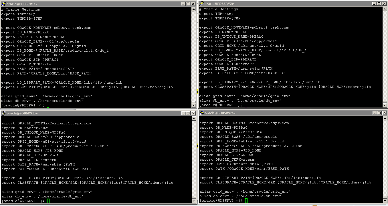
The environment variables from .bash_profile, grid_env and db_env on all four nodes will look similar to like as shown in image below.
You need to increase /dev/shm size if it is less than 4GB using the following command. If you don’t increase, it will cause an error during prerequisites check of Grid installation.
mount -o remount 4G /dev/shm
To make it persistent even after reboot, you need to modify /etc/fstab accordingly
vi /etc/fstab
tmpfs /dev/shm tmpfs defaults,size=4G 0 0
Save and close
Since, we have already added and configured iSCSI storage on all four nodes, now we need to create diskgroup of shared storage using the following command on Primary Node PDBSRV1 and later we will initialize and scan same diskgroup on PDBSRV2.
[root@PDBSRV1 ~]# oracleasm configure -i
Configuring the Oracle ASM library driver.
This will configure the on-boot properties of the Oracle ASM library
driver. The following questions will determine whether the driver is
loaded on boot and what permissions it will have. The current values
will be shown in brackets ('[]'). Hitting without typing an
answer will keep that current value. Ctrl-C will abort.
Default user to own the driver interface [oracle]:
Default group to own the driver interface [dba]:
Start Oracle ASM library driver on boot (y/n) [y]:
Scan for Oracle ASM disks on boot (y/n) [y]:
Writing Oracle ASM library driver configuration: done
[root@PDBSRV1 ~]# oracleasm createdisk DISK1 /dev/sdc1
[root@PDBSRV1 ~]# oracleasm createdisk DISK2 /dev/sdd1
[root@PDBSRV1 ~]# oracleasm createdisk DISK3 /dev/sde1
[root@PDBSRV1 ~]# oracleasm scandisks
[root@PDBSRV1 ~]# oracleasm listdisks
DISK1
DISK2
DISK3
Now initialize and scan same diskgroup and PDBSRV2 using the following command.
[root@PDBSRV2 ~]# oracleasm configure -i
Configuring the Oracle ASM library driver.
This will configure the on-boot properties of the Oracle ASM library
driver. The following questions will determine whether the driver is
loaded on boot and what permissions it will have. The current values
will be shown in brackets ('[]'). Hitting without typing an
answer will keep that current value. Ctrl-C will abort.
Default user to own the driver interface [oracle]:
Default group to own the driver interface [dba]:
Start Oracle ASM library driver on boot (y/n) [y]:
Scan for Oracle ASM disks on boot (y/n) [y]:
Writing Oracle ASM library driver configuration: done
[root@PDBSRV2 ~]# oracleasm scandisks
[root@PDBSRV2 ~]# oracleasm listdisks
DISK1
DISK2
DISK3
Now, we will create diskgroup on our Standby node SDBSRV1 and later we will initialize and scan same diskgroup on SDBSRV2.
[root@SDBSRV1 ~]# oracleasm configure -i
Configuring the Oracle ASM library driver.
This will configure the on-boot properties of the Oracle ASM library
driver. The following questions will determine whether the driver is
loaded on boot and what permissions it will have. The current values
will be shown in brackets ('[]'). Hitting without typing an
answer will keep that current value. Ctrl-C will abort.
Default user to own the driver interface [oracle]:
Default group to own the driver interface [dba]:
Start Oracle ASM library driver on boot (y/n) [y]:
Scan for Oracle ASM disks on boot (y/n) [y]:
Writing Oracle ASM library driver configuration: done
[root@SDBSRV1 ~]# oracleasm createdisk DISK1 /dev/sdc1
[root@SDBSRV1 ~]# oracleasm createdisk DISK2 /dev/sdd1
[root@SDBSRV1 ~]# oracleasm createdisk DISK3 /dev/sde1
[root@SDBSRV1 ~]# oracleasm scandisks
[root@SDBSRV1 ~]# oracleasm listdisks
DISK1
DISK2
DISK3
Now initialize and scan same diskgroup on SDBSRV2 using the following command.
[root@SDBSRV2 ~]# oracleasm configure -i
Configuring the Oracle ASM library driver.
This will configure the on-boot properties of the Oracle ASM library
driver. The following questions will determine whether the driver is
loaded on boot and what permissions it will have. The current values
will be shown in brackets ('[]'). Hitting without typing an
answer will keep that current value. Ctrl-C will abort.
Default user to own the driver interface [oracle]:
Default group to own the driver interface [dba]:
Start Oracle ASM library driver on boot (y/n) [y]:
Scan for Oracle ASM disks on boot (y/n) [y]:
Writing Oracle ASM library driver configuration: done
[root@SDBSRV2 ~]# oracleasm scandisks
[root@SDBSRV2 ~]# oracleasm listdisks
DISK1
DISK2
DISK3
Installing Grid Infrastructure 12c - Primary Site
We have completed the preparation of all four machines and ready to start Oracle grid infrastructure 12c installation. You should have either VNC or Xmanager installed on your client machine for graphical installation of grid/database. In our case, we have windows 7 client machine and we are using Xmanager.
Now, copy grid infrastructure and database software on your primary node PDBSRV1 and extract it under /opt or any other directory of your choice. In our case, we have CD Rom media and we will extract it under /opt.
Login using root user on your primary node PDBSRV1 and perform the following steps.
unzip -q /media/linuxamd64_12c_grid_1of2.zip -d /opt
unzip -q /media/linuxamd64_12c_grid_2of2.zip -d /opt
unzip -q /media/linuxamd64_12c_database_1of2.zip -d /opt
unzip -q /media/linuxamd64_12c_database_2of2.zip -d /opt
Copy cvuqdisk-1.0.9-1.rpm to other three nodes under /opt and install it on each node one by one
scp -p /opt/grid/rpm/cvuqdisk-1.0.9-1.rpm pdbsrv2:/opt
scp -p /opt/grid/rpm/cvuqdisk-1.0.9-1.rpm sdbsrv1:/opt
scp -p /opt/grid/rpm/cvuqdisk-1.0.9-1.rpm sdbsrv2:/opt
rpm -Uvh /opt/grid/rpm/cvuqdisk-1.0.9-1.rpm
Now, logout from root user and login again with oracle user to perform grid installation on your primary node PDBSRV1
Run grid_env to set environment variable for grid infrastructure installation.
[oracle@PDBSRV1 ~]$ grid_env
[oracle@PDBSRV1 ~]$ export DISPLAY=192.168.10.1:0.0
Now, execute the following command from the directory you have extracted grid in to begin the installation.
[oracle@PDBSRV1 grid]$ /opt/grid/runInstaller
Follow the screenshots to set up grid infrastructure according to your environment.
Select"Skip Software Update" Click Next
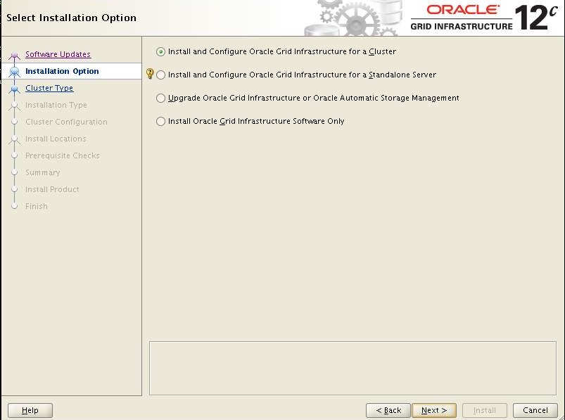
Select "Install and Configure Oracle Grid Infrastructure for a Cluster" Click Next
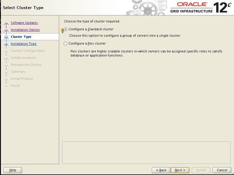
Select "Configure a Standard Cluster" Click Next
Choose "Typical Installation" Click Next
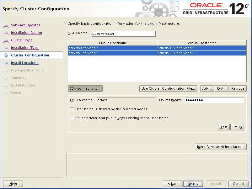
Change the "SCAN Name" and add secondary host in the cluster, enter oracle user password then Click Next.
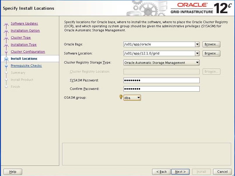
Verify destination path, enter password and choose "dba" as OSASM group. Click Next
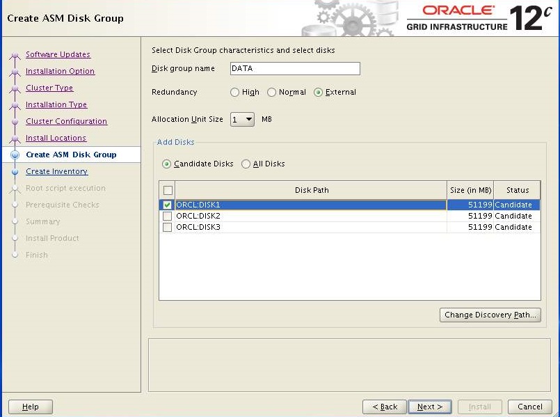
Click "External" for redundancy and select at least one disk or more and Click Next.
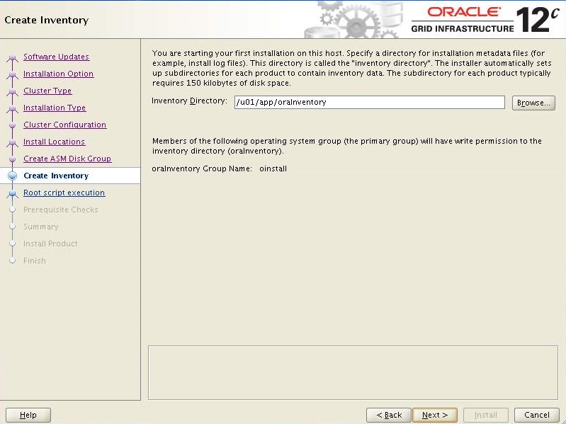
Keep the default and Click Next
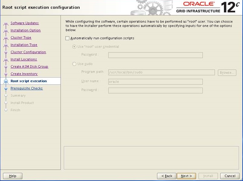
Keep the default and Click Next
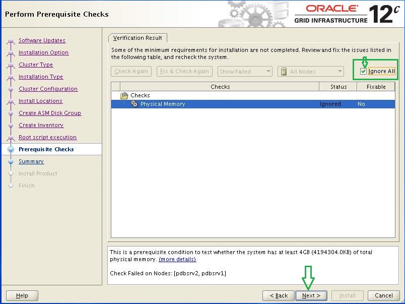
It is safe to ignore since i can not add more than 4GB of memory. Click Next
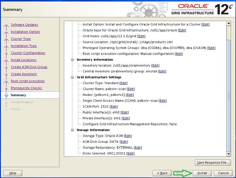
Verify and if you are happy with the summary, Click Install.
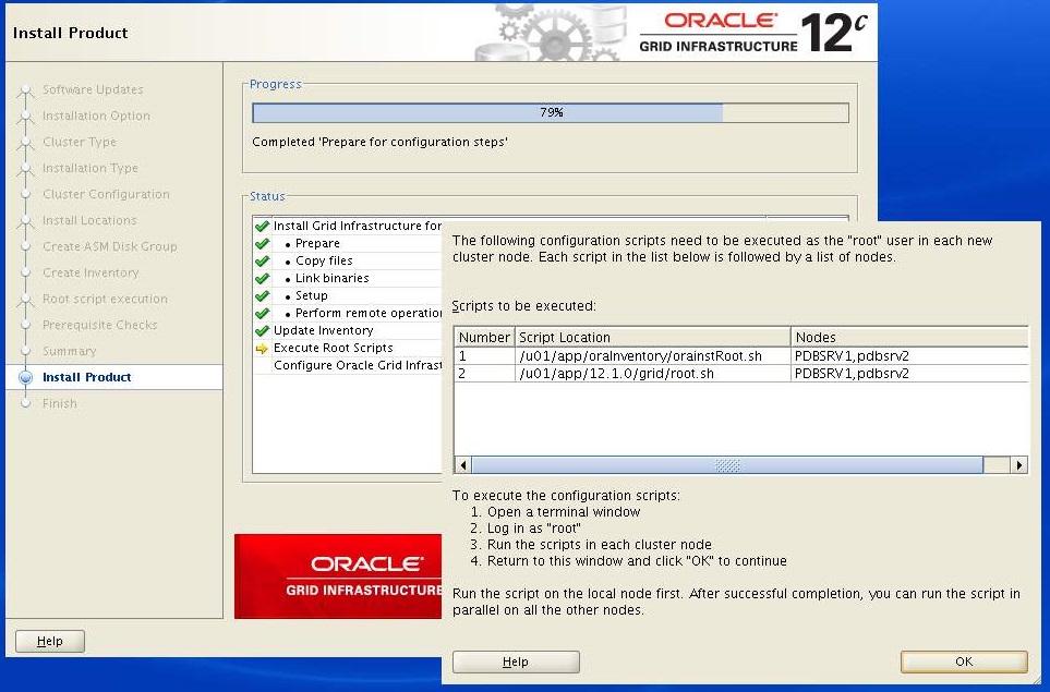
Now, stop when the following screen appears and do not click OK. Now login with root user on PDBSRV1 and PDBSRV2 to execute the following scripts. You must execute both scripts on PDBSRV1 first.
[root@PDBSRV1 ~]# /u01/app/oracle/product/12.1.0/db_1/root.sh [root@PDBSRV1 ~]# /u01/app/12.1.0/grid/root.sh When you are done on PDBSRV1 then execute both scripts on PDBSRV2
[root@PDBSRV1 ~]# /u01/app/oracle/product/12.1.0/db_1/root.sh [root@PDBSRV1 ~]# /u01/app/12.1.0/grid/root.sh
When done, Click OK.
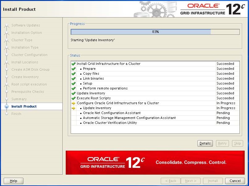
Setup will continue after successful execution of scripts on both nodes.
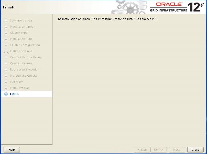
Click close.
At this point, Grid infrastructure 12c installation completed. We can check the status of the installation using the following commands.[oracle@PDBSRV1 ~]$ grid_env
[oracle@PDBSRV1 ~]$ crsctl stat res -t
Note: If you found ora.oc4j offline then you can enable and start it manually by executing the following command.[oracle@PDBSRV1 ~]$ crsctl enable ora.oc4j
[oracle@PDBSRV1 ~]$ crsctl start ora.oc4j
[oracle@PDBSRV1 ~]$ crsctl stat res -t
Installing Oracle Database 12c - Primary Site
Since we have completed grid installation, now we need to install oracle database 12c by executing runInstaller command from the directory you have extracted the database in.
[oracle@PDBSRV1 ~]$db_env
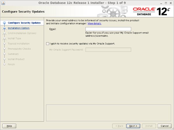
[oracle@PDBSRV1 ~]$ /opt/database/runInstaller
Uncheck the security updates checkbox and click the "Next" button and "Yes" on the subsequent warning dialog.
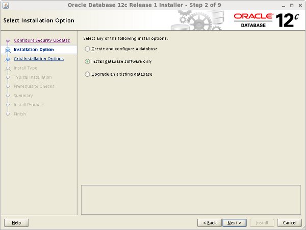
Select the "Install database software only" option, then click the "Next" button.
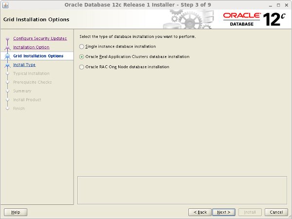
Accept the "Oracle Real Application Clusters database installation" option by clicking the "Next" button.
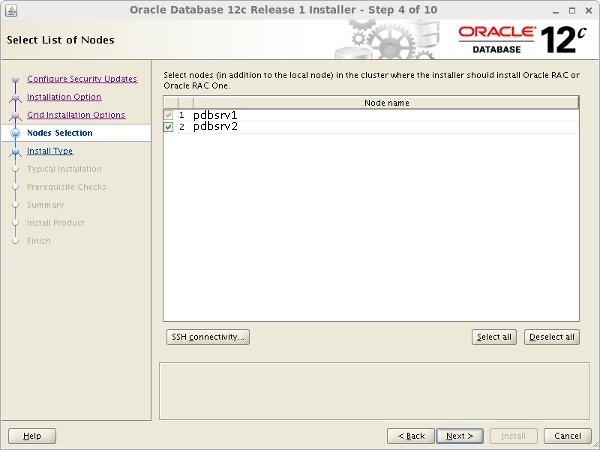
Make sure both nodes are selected, then click the "Next" button.
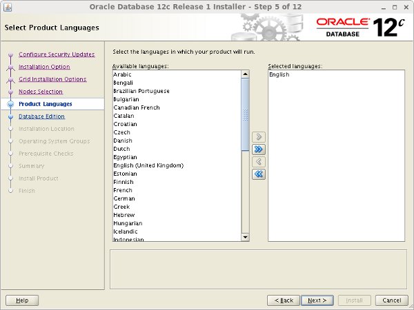
Select the required languages, then click the "Next" button.
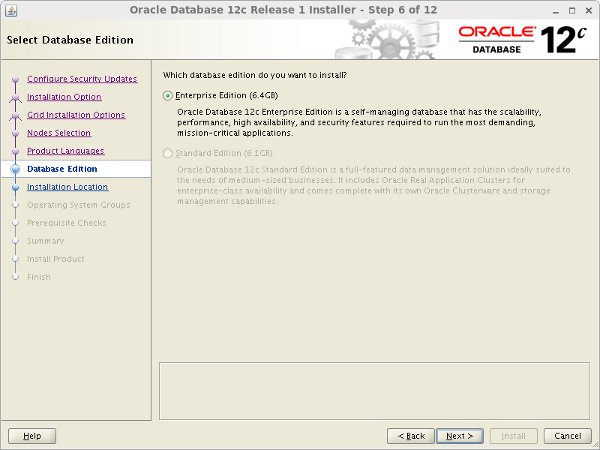
Select the "Enterprise Edition" option, then click the "Next" button.
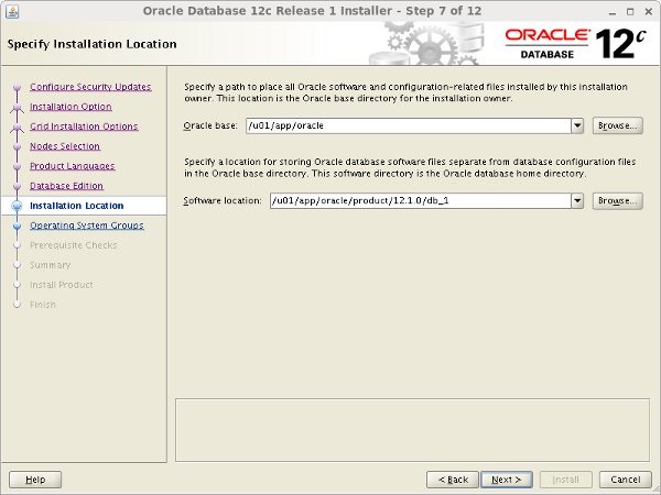
Enter "/u01/app/oracle" as the Oracle base and "/u01/app/oracle/product/12.1.0/db_1" as the software location, then click the "Next" button.
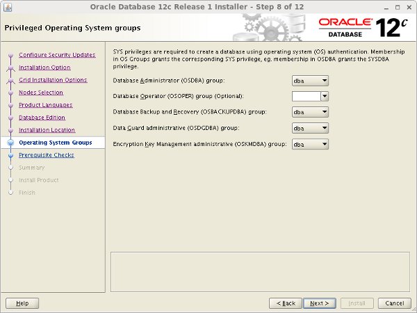
Select the desired operating system groups, then click the "Next" button.
Wait for the prerequisite check to complete. If there are any problems either click the "Fix & Check Again" button, or check the "Ignore All" checkbox and click the "Next" button.
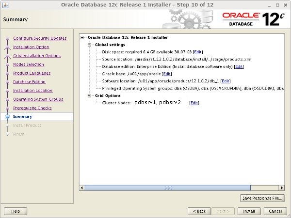
If you are happy with the summary information, click the "Install" button.
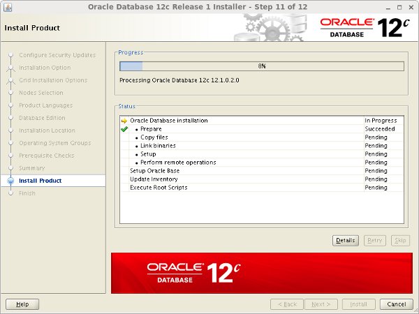
Wait while the installation takes place.
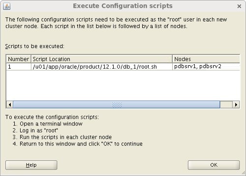
When prompted, run the configuration script on each node. When the scripts have been run on each node, click the "OK" button.
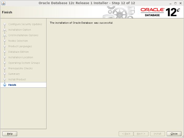
Click the "Close" button to exit the installer.
At this stage, database installation completed.
Creating a Database - Primary Site
Since we have completed database installation, its time to create a database by executing the following command.
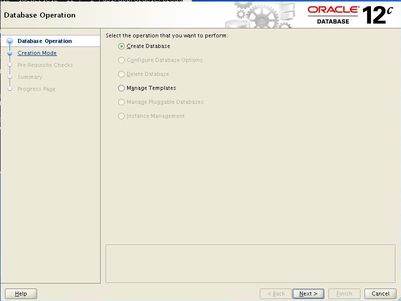
[oracle@PDBSRV1 ~]$ db_env[oracle@PDBSRV1 ~]$ dbca
Select the "Create Database" option and click the "Next" button.
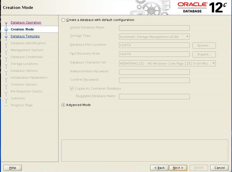
Select the "Advanced Mode" option. Click the "Next" button.
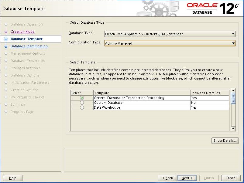
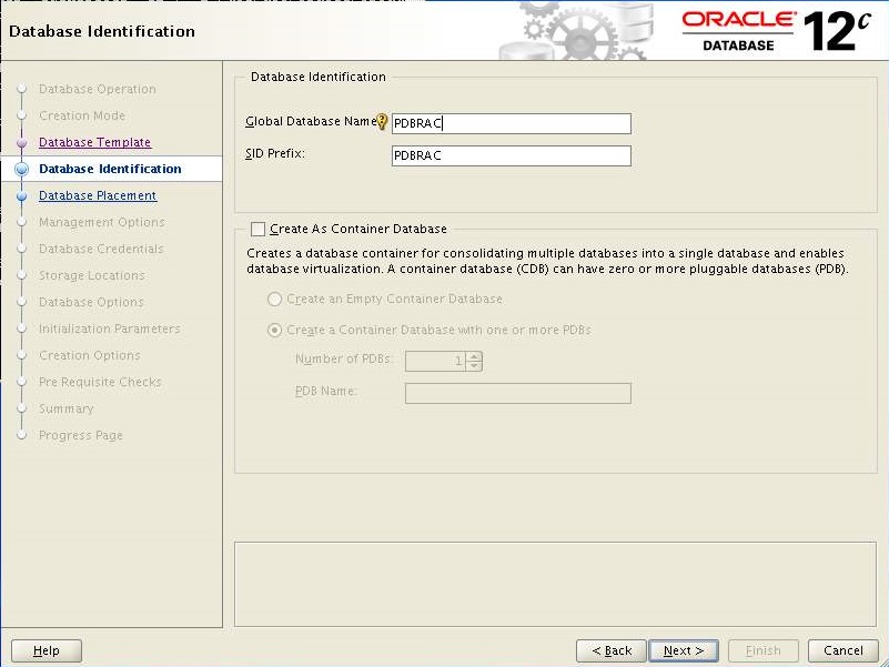
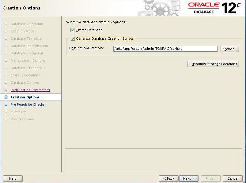
Select exactly what shown in image and Click Next.
Enter the "PDBRAC" in database name and keep the SID as is. Click Next
Make sure both nodes are select and Click Next
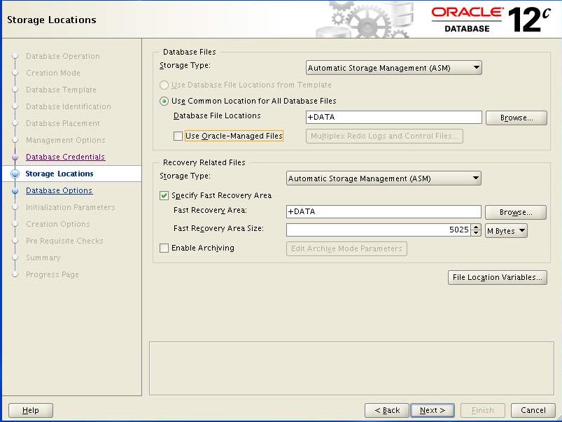
Keep the default and Click Next
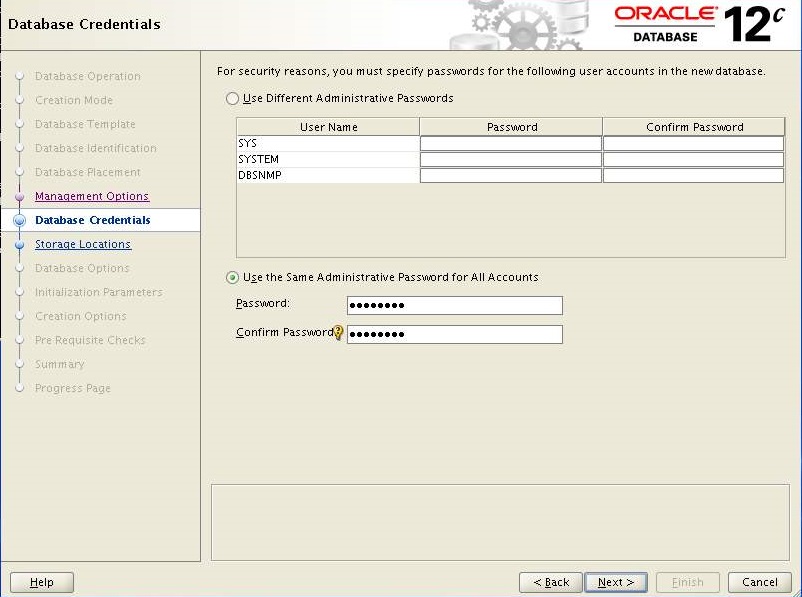
Select "Use the Same Administrative password for All Accounts" enter the password and Click Next
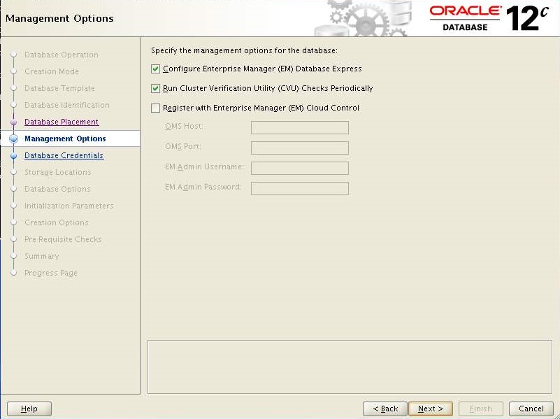
Keep the defaults and Click Next.
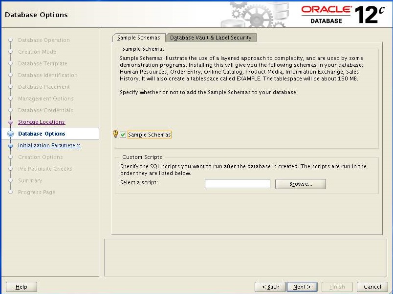
Select "Sample Schema" we need it for testing purpose later and Click Next
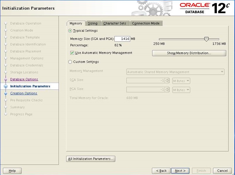
Increase "Memory Size" and navigate to "Sizing" tab
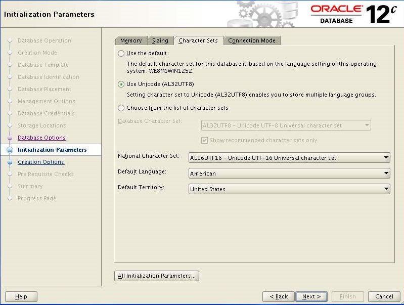
Increase the "Processes" and navigate to "Character Sets" tab
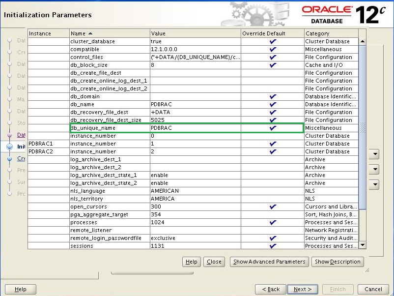
Select the following options and Click "All Initialization Parameters"
Define "PDBRAC" in db_unique_name and click Close.
Click Next
Select the below options and click Next.
If you happy with the Summary report then Click Finish.
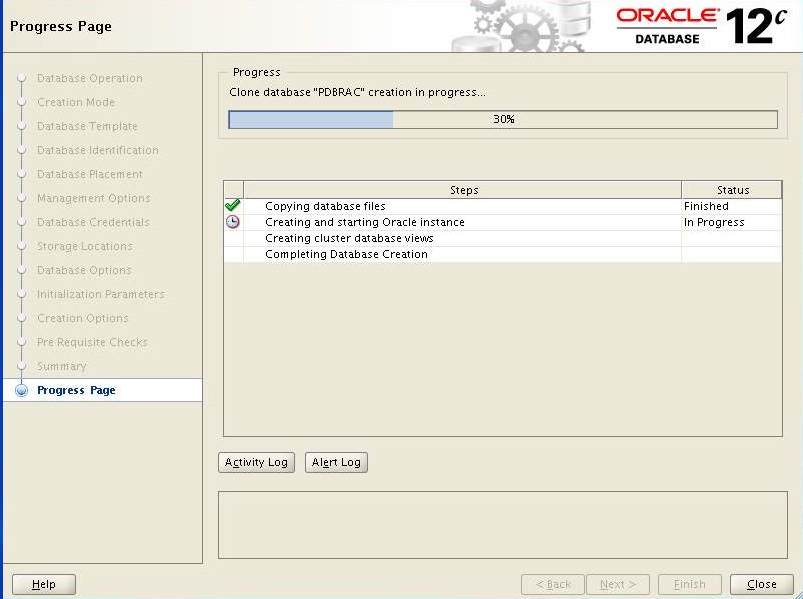
Database creation process started, it will take several time to complete.
Click ExitClick Close
We have successfully created a database on Primary nodes (pdbsrv1, pdbsrv2). We can check database status by executing the following command.
[oracle@PDBSRV1 ~]$ grid_env[oracle@PDBSRV1 ~]$ srvctl status database -d pdbrac
Instance PDBRAC1 is running on node pdbsrv1
Instance PDBRAC2 is running on node pdbsrv2
[oracle@PDBSRV1 ~]$ srvctl config database -d pdbrac
Database unique name: PDBRAC
Database name: PDBRAC
Oracle home: /u01/app/oracle/product/12.1.0/db_1
Oracle user: oracle
Spfile: +DATA/PDBRAC/spfilePDBRAC.ora
Password file: +DATA/PDBRAC/orapwpdbrac
Domain:
Start options: open
Stop options: immediate
Database role: PRIMARY
Management policy: AUTOMATIC
Server pools: PDBRAC
Database instances: PDBRAC1,PDBRAC2
Disk Groups: DATA
Mount point paths:
Services:
Type: RAC
Start concurrency:
Stop concurrency:
Database is administrator managed
[oracle@PDBSRV1 ~]$ db_env
[oracle@PDBSRV1 ~]$ sqlplus / as sysdba
SQL> SELECT inst_name FROM v$active_instances;
INST_NAME
--------------------------------------------------------------------------------
PDBSRV1.TSPK.COM:PDBRAC1
PDBSRV2.TSPK.COM:PDBRAC2
SQL>exit
Installing Grid Infrastructure 12c - Standby Site
Since we have already installed all perquisites on our Standby site nodes (sdbsrv1, sdbsrv2) for grid/database installation, we can start grid installation straightaway.
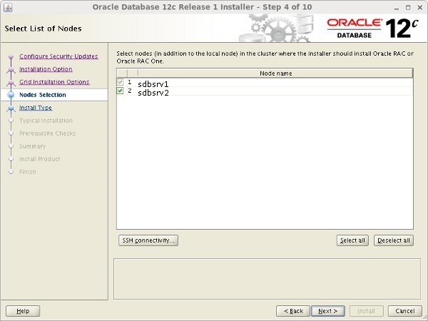
Login to sdbsrv1 using oracle user and execute the following command to being the installation. Follow the same steps you have performed during installation on primary site nodes with minor changes as show in image below.![]()
[oracle@SDBSRV1 grid]$ grid_env[oracle@SDBSRV1 grid]$ export DISPLAY=192.168.10.1:0.0[oracle@SDBSRV1 grid]$ /opt/grid/runInstaller
Enter "SCAN Name" and add secondadry node "sdbsrv1" enter oracle user password in "OS Password" box and Click Next
Once the grid installation completed, we can check the status of the installation using the following commands.[oracle@SDBSRV1 ~]$ grid_env
[oracle@SDBSRV1 ~]$ crsctl stat res -t
Note: If you found ora.oc4j offline then you can enable and start it manually by executing the following command.
[oracle@SDBSRV1 ~]$ crsctl enable ora.oc4j
[oracle@SDBSRV1 ~]$ crsctl start ora.oc4j
[oracle@SDBSRV1 ~]$ crsctl stat res -t
Installing Database 12c - Standby Site
We can start database 12c installation by following the same steps we have performed during installation on primary nodes with minor changes as shown in images below.
[oracle@SDBSRV1 ~]$ db_env[oracle@SDBSRV1 ~]$ /opt/database/runInstaller
![]()
You do not need to run "dbca" to create database on Standby nodes. Once the database installation completed, we can start configuring data guard at Primary nodes first.
Data Guard Configuration - Primary Site
Login to PDBSRV1 using oracle user and perform the following tasks to prepare data guard configuration.
[oracle@PDBSRV1 ~]$ db_env[oracle@PDBSRV1 ~]$ mkdir /u01/app/oracle/backup[oracle@PDBSRV1 ~]$ sqlplus / as sysdba
Connected to:Oracle Database 12c Enterprise Edition Release 12.1.0.1.0 - 64bit ProductionWith the Partitioning, Real Application Clusters, Automatic Storage Management, OLAP,Advanced Analytics and Real Application Testing options
SQL> alter database force logging;
SQL> alter database open;
SQL> alter system set log_archive_config='DG_CONFIG=(PDBRAC,SDBRAC)' scope=both sid='*';
SQL> alter system set log_archive_dest_1='LOCATION=USE_DB_RECOVERY_FILE_DEST VALID_FOR=(ALL_LOGFILES,ALL_ROLES) DB_UNIQUE_NAME=PDBRAC' scope=both sid='*';
SQL> alter system set LOG_ARCHIVE_DEST_2='SERVICE=SDBRAC SYNC NOAFFIRM VALID_FOR=(ONLINE_LOGFILES,PRIMARY_ROLE) DB_UNIQUE_NAME=SDBRAC' scope=both sid='*';
SQL> alter system set log_archive_format='%t_%s_%r.arc' scope=spfile sid='*';SQL> alter system set LOG_ARCHIVE_MAX_PROCESSES=8 scope=both sid='*';SQL> alter system set REMOTE_LOGIN_PASSWORDFILE=EXCLUSIVE scope=both sid='*';SQL> alter system set fal_server = 'SDBRAC';SQL> alter system set STANDBY_FILE_MANAGEMENT=AUTO scope=spfile sid='*';SQL> alter database flashback ON;SQL> select group#,thread#,bytes from v$log;
SQL> ALTER DATABASE ADD STANDBY LOGFILE THREAD 1 ('+DATA') SIZE 50M;SQL> ALTER DATABASE ADD STANDBY LOGFILE THREAD 1 ('+DATA') SIZE 50M;SQL> ALTER DATABASE ADD STANDBY LOGFILE THREAD 1 ('+DATA') SIZE 50M;SQL> ALTER DATABASE ADD STANDBY LOGFILE THREAD 1 ('+DATA') SIZE 50M;
SQL> ALTER DATABASE ADD STANDBY LOGFILE THREAD 2 ('+DATA') SIZE 50M;SQL> ALTER DATABASE ADD STANDBY LOGFILE THREAD 2 ('+DATA') SIZE 50M;SQL> ALTER DATABASE ADD STANDBY LOGFILE THREAD 2 ('+DATA') SIZE 50M;SQL> ALTER DATABASE ADD STANDBY LOGFILE THREAD 2 ('+DATA') SIZE 50M;
SQL> select group#,thread#,bytes from v$standby_log;
SQL> create pfile='/u01/app/oracle/backup/initSDBRAC.ora' from spfile;
SQL> exit
[oracle@PDBSRV1 ~]$ grid_env[oracle@PDBSRV1 ~]$ asmcmd pwget --dbuniquename PDBRAC[oracle@PDBSRV1 ~]$ asmcmd pwcopy --dbuniquename PDBRAC '+DATA/PDBRAC/orapwpdbrac''/u01/app/oracle/backup/orapwsdbrac'
[oracle@PDBSRV1 ~]$ db_env[oracle@PDBSRV1 ~]$ rman target / nocatalogRMAN> run{ sql "alter system switch logfile"; allocate channel ch1 type disk format '/u01/app/oracle/backup/Primary_bkp_for_standby_%U'; backup database; backup current controlfile for standby; sql "alter system archive log current";}
RMAN> exit
Update $ORACLE_HOME/network/admin/tnsnames.ora file on PDBSRV1
[oracle@PDBSRV1 ~]$ vi $ORACLE_HOME/network/admin/tnsnames.ora
PDBRAC = (DESCRIPTION = (ADDRESS = (PROTOCOL = TCP)(HOST = pdbsrv-scan)(PORT = 1521)) (CONNECT_DATA = (SERVER = DEDICATED) (SERVICE_NAME = PDBRAC) ) )
PDBRAC1 = (DESCRIPTION = (ADDRESS = (PROTOCOL = TCP)(HOST = pdbsrv1-vip)(PORT = 1521)) (CONNECT_DATA = (SERVER = DEDICATED) (SERVICE_NAME = PDBRAC) (SID = PDBRAC1) ) )
PDBRAC2 = (DESCRIPTION = (ADDRESS = (PROTOCOL = TCP)(HOST = pdbsrv2-vip)(PORT = 1521)) (CONNECT_DATA = (SERVER = DEDICATED) (SERVICE_NAME = SDBRAC) (SID = PDBRAC2) ) )
SDBRAC = (DESCRIPTION = (ADDRESS = (PROTOCOL = TCP)(HOST = sdbsrv-scan)(PORT = 1521)) (CONNECT_DATA = (SERVER = DEDICATED) (SERVICE_NAME = SDBRAC) ) )
SDBRAC1 = (DESCRIPTION = (ADDRESS = (PROTOCOL = TCP)(HOST = sdbsrv1-vip)(PORT = 1521)) (CONNECT_DATA = (SERVER = DEDICATED) (SERVICE_NAME = SDBRAC) (SID = SDBRAC1) ) )
SDBRAC2 = (DESCRIPTION = (ADDRESS = (PROTOCOL = TCP)(HOST = sdbsrv2-vip)(PORT = 1521)) (CONNECT_DATA = (SERVER = DEDICATED) (SERVICE_NAME = SDBRAC) (SID = SDBRAC2) ) )
Save and close
Copy the tnsnames.ora from PDBSRV1 to all the three nodes under $ORACLE_HOME/network/admin in order to keep the same tnsnames.ora on all the nodes.
[oracle@PDBSRV1 ~]$ scp -p $ORACLE_HOME/network/admin/tnsnames.ora pdbsrv2:$ORACLE_HOME/network/admin
[oracle@PDBSRV1 ~]$ scp -p $ORACLE_HOME/network/admin/tnsnames.ora sdbsrv1:$ORACLE_HOME/network/admin
[oracle@PDBSRV1 ~]$ scp -p $ORACLE_HOME/network/admin/tnsnames.ora sdbsrv2:$ORACLE_HOME/network/admin
Copy initSDBRAC.ora and orapwsdbrac from primary node PDBSRV1 to standby nodes SDBSRV1, SDBSRV2
[oracle@PDBSRV1 ~]$ scp /u01/app/oracle/backup/initSDBRAC.ora oracle@dbsrv1:/u01/app/oracle/product/12.1.0/db_1/dbs/initSDBRAC.ora
[oracle@PDBSRV1 ~]$ scp /u01/app/oracle/backup/orapwsdbrac oracle@sdbsrv1:/u01/app/oracle/backup/orapwsdbrac
Copy /u01/app/oracle/backup from primary node pdbsrv1 to standby node sdbsrv1 under the same location as primary
[oracle@PDBSRV1 ~]$ scp -r /u01/app/oracle/backup sdbsrv1:/u01/app/oracle
Data Guard Configuration - Standby Site
Login to SDBSRV1, SDBSRV2 using oracle user and perform the following tasks to prepare Standby site data guard configuration.
[oracle@SDBSRV1 ~]$ mkdir /u01/app/oracle/admin/SDBRAC/adump[oracle@SDBSRV2 ~]$ mkdir /u01/app/oracle/admin/SDBRAC/adump
Now modify initSDBRAC.ora file similiar to like below
[oracle@SDBSRV1 ~]$ vi /u01/app/oracle/product/12.1.0/db_1/dbs/initSDBRAC.ora
SDBRAC1.__data_transfer_cache_size=0
SDBRAC2.__data_transfer_cache_size=0
SDBRAC1.__db_cache_size=184549376
SDBRAC2.__db_cache_size=452984832
SDBRAC1.__java_pool_size=16777216
SDBRAC2.__java_pool_size=16777216
SDBRAC1.__large_pool_size=419430400
SDBRAC2.__large_pool_size=33554432
SDBRAC1.__oracle_base='/u01/app/oracle'#ORACLE_BASE set from environment
SDBRAC2.__oracle_base='/u01/app/oracle'#ORACLE_BASE set from environment
SDBRAC1.__pga_aggregate_target=520093696
SDBRAC2.__pga_aggregate_target=570425344
SDBRAC1.__sga_target=973078528
SDBRAC2.__sga_target=922746880
SDBRAC1.__shared_io_pool_size=0
SDBRAC2.__shared_io_pool_size=33554432
SDBRAC1.__shared_pool_size=335544320
SDBRAC2.__shared_pool_size=369098752
SDBRAC1.__streams_pool_size=0
SDBRAC2.__streams_pool_size=0
*.audit_file_dest='/u01/app/oracle/admin/SDBRAC/adump'
*.audit_trail='db'
*.cluster_database=true
*.compatible='12.1.0.0.0'
*.control_files='+DATA/SDBRAC/control01.ctl','+DATA/SDBRAC/control02.ctl'
*.db_block_size=8192
*.db_domain=''
*.db_name='PDBRAC'
*.db_recovery_file_dest='+DATA'
*.db_recovery_file_dest_size=5025m
*.db_unique_name='SDBRAC'
*.diagnostic_dest='/u01/app/oracle'
*.dispatchers='(PROTOCOL=TCP) (SERVICE=SDBRACXDB)'
*.fal_server='PDBRAC'
SDBRAC1.instance_number=1
SDBRAC2.instance_number=2
*.log_archive_config='DG_CONFIG=(SDBRAC,PDBRAC)'
*.log_archive_dest_1='LOCATION=USE_DB_RECOVERY_FILE_DEST VALID_FOR=(ALL_LOGFILES,ALL_ROLES) DB_UNIQUE_NAME=SDBRAC'
*.log_archive_dest_2='service=PDBRAC async valid_for=(online_logfile,primary_role) db_unique_name=PDBRAC'
*.log_archive_format='%t_%s_%r.arc'
*.log_archive_max_processes=8
*.memory_target=1416m
*.open_cursors=300
*.processes=1024
*.remote_login_passwordfile='EXCLUSIVE'
*.sessions=1131
*.standby_file_management='AUTO'
SDBRAC2.thread=2
SDBRAC1.thread=1
SDBRAC2.undo_tablespace='UNDOTBS2'
SDBRAC1.undo_tablespace='UNDOTBS1'
Save and close
Now create the ASM directories
[oracle@SDBSRV1 ~]$ grid_env[oracle@SDBSRV1 ~]$ asmcmd mkdir DATA/SDBRAC[oracle@SDBSRV1 ~]$ asmcmd
ASMCMD> cd DATA/SDBRACASMCMD> mkdir PARAMETERFILE DATAFILE CONTROLFILE TEMPFILE ONLINELOG ARCHIVELOG STANDBYLOGASMCMD> exit
Configure static listener configuration in the listener.ora file on standby nodes. Add entry similar to below at the end in listener.ora file. The reason for this is that our standby database will be in nomount stage. In NOMOUNT stage, the database instance will not self-register with the listener, so you must tell the listener it is there.
[oracle@SDBSRV1 ~]$ cp -p /u01/app/12.1.0/grid/network/admin/listener.ora /u01/app/12.1.0/grid/network/admin/listener.ora.bkp
[oracle@SDBSRV1 ~]$ vi /u01/app/12.1.0/grid/network/admin/listener.ora SID_LIST_LISTENER =(SID_LIST = (SID_DESC = (SID_NAME = SDBRAC) (ORACLE_HOME = /u01/app/oracle/products/12.1.0/db_1) ))
Save and close
[oracle@SDBSRV1 ~]$scp -p /u01/app/12.1.0/grid/network/admin/listener.ora sdbsrv2:/u01/app/12.1.0/grid/network/admin/listener.ora
Now stop and start the LISTENER using srvctl command
[oracle@SDBSRV1 ~]$ grid_env[oracle@SDBSRV1 ~]$ srvctl stop listener -listener LISTENER[oracle@SDBSRV1 ~]$ srvctl start listener -listener LISTENER
[oracle@SDBSRV2 ~]$ grid_env[oracle@SDBSRV2 ~]$ srvctl stop listener -listener LISTENER[oracle@SDBSRV2 ~]$ srvctl start listener -listener LISTENER
Create physical standby database
[oracle@SDBSRV1 ~]$ db_env
[oracle@SDBSRV1 ~]$ sqlplus / as sysdba
SQL> startup nomount pfile='/u01/app/oracle/product/12.1.0/db_1/dbs/initSDBRAC.ora'
SQL> exit
Login to Primary server pdbsrv1 as oracle user, connect to both Primary and Standby databases as shown below and run the RMAN active database duplication command.
[oracle@PDBSRV1 ~]$ rman target sys@PDBRAC auxiliary sys@SDBRAC
target database Password:
connected to target database: PDBRAC (DBID=2357433135)
auxiliary database Password:
connected to auxiliary database: PDBRAC (not mounted)
RMAN> DUPLICATE TARGET DATABASE FOR STANDBY NOFILENAMECHECK;
RMAN> exit
Now that the Standby database is created, first we need to check whether the Redo Apply is working or not before proceeding with the next steps. Using the below command start the Redo Apply.
[oracle@SDBSRV1 ~]$ db_env[oracle@SDBSRV1 ~]$ sqlplus / as sysdba
SQL> ALTER DATABASE RECOVER MANAGED STANDBY DATABASE USING CURRENT LOGFILE DISCONNECT FROM SESSION;
The above command starts the recovery process using the standby logfiles that the primary is writing the redo to. It also tells the standby to return to the SQL command line once the command is complete.
Verifying that Redo Apply is working. You can run the below query to check the status of different processes.
SQL> select PROCESS, PID, STATUS, THREAD#, SEQUENCE# from v$managed_standby;
PROCESS PID STATUS THREAD# SEQUENCE#--------- ------------------------ ------------ ---------- ----------ARCH 27871 CONNECTED 0 0ARCH 27873 CONNECTED 0 0ARCH 27875 CONNECTED 0 0ARCH 27877 CLOSING 2 52RFS 7084 IDLE 0 0RFS 7064 IDLE 2 53RFS 7080 IDLE 0 0RFS 7082 IDLE 0 0RFS 7122 IDLE 0 0RFS 7120 IDLE 1 76RFS 7136 IDLE 0 0RFS 7138 IDLE 0 0MRP0 14050 APPLYING_LOG 2 53
To check whether the Primary and Standby databases are in sync or not, execute below query.
On Primary:
SQL> select THREAD#, max(SEQUENCE#) from v$log_history group by thread#;
THREAD# MAX(SEQUENCE#)---------- -------------- 1 78 2 53
On Standby:
SQL> select max(sequence#), thread# from v$archived_log where applied='YES' group by thread#;
MAX(SEQUENCE#) THREAD#-------------- ---------- 78 1 52 2
Create new spfile from pfile:
[oracle@SDBSRV1 ~]$ db_env[oracle@SDBSRV1 ~]$ sqlplus / as sysdba
SQL> create pfile='/u01/app/oracle/products/12.1.0/db_1/dbs/initSDBRAC.ora' from spfile;
SQL> shutdown immediate;SQL> exit
Now remove the static listener entry from standby nodes sdbsrv1, sdbsrv2 that we had added in listener.ora file earlier. Save the changes and restart the local listener.
[oracle@SDBSRV1 ~]$ cp -p /u01/app/12.1.0/grid/network/admin/listener.ora.bkp /u01/app/12.1.0/grid/network/admin/listener.ora
[oracle@SDBSRV1 ~]$ scp /u01/app/12.1.0/grid/network/admin/listener.ora sdbsrv2:/u01/app/12.1.0/grid/network/admin/listener.ora
Now start the standby database using the newly created pfile. If everything is proper then the instance should get started.
[oracle@SDBSRV1 ~]$ db_env[oracle@SDBSRV1 ~]$ sqlplus / as sysdba
SQL> startup nomount pfile='/u01/app/oracle/products/12.1.0/db_1/dbs/initSDBRAC.ora';ORACLE instance started.
Total System Global Area 1358954496 bytesFixed Size 2924208 bytesVariable Size 469762384 bytesDatabase Buffers 872415232 bytesRedo Buffers 13852672 bytesSQL>
SQL> alter database mount standby database;
Database altered.
SQL>
Now that the Standby database has been started with the cluster parameters enabled, we will create Spfile in the central location on ASM diskgroup.
SQL> create spfile='+DATA/SDBRAC/spfileSDBRAC.ora' from pfile='/u01/app/oracle/products/12.1.0/db_1/dbs/initSDBRAC.ora';
SQL> shutdown immediate;SQL> exit
Now we need to check whether the standby database gets started using our new spfile which we created on ASM diskgroup. Before proceeding with below steps, first shutdown the database.
Rename the old pfile and spfile in $ORACLE_HOME/dbs directory.
[oracle@SDBSRV1 ~]$ cd $ORACLE_HOME/dbs
[oracle@SDBSRV1 ~]$ mv initSDBRAC.ora initSDBRAC.ora.orig[oracle@SDBSRV1 ~]$ mv spfileSDBRAC.ora spfileSDBRAC.ora.orig
Now create the below initSDBRAC1.ora file on sdbsrv1 and initSDBRAC2.ora file on sdbsrv2 under $ORACLE_HOME/dbs with the spfile entry so that the instance can start with the newly created spfile.
[oracle@SDBSRV1 ~]$ cd $ORACLE_HOME/dbs
[oracle@SDBSRV1 ~]$ vi initSDBRAC1.oraspfile='+DATA/SDBRAC/spfileSDBRAC.ora'
Save and close
copy initSDBRAC1.ora to sdbsrv2 as $ORACLE_HOME/dbs/initSDBRAC2.ora
[oracle@SDBSRV1 ~]$ scp -p $ORACLE_HOME/dbs/initSDBRAC1.ora sdbsrv2:$ORACLE_HOME/dbs/initSDBRAC2.ora
Now start the database on sdbsrv1
[oracle@SDBSRV1 ~]$ db_env[oracle@SDBSRV1 ~]$ sqlplus / as sysdba
SQL> startup mount;ORACLE instance started.
Total System Global Area 1358954496 bytesFixed Size 2924208 bytesVariable Size 469762384 bytesDatabase Buffers 872415232 bytesRedo Buffers 13852672 bytesDatabase mounted.
SQL> select name, open_mode from v$database;
NAME OPEN_MODE--------- --------------------SDBRAC MOUNTED
SQL> show parameter spfile;
NAME TYPE VALUE------------------------------------ ----------- -------------------------------spfile string +DATA/SDBRAC/spfileSDBRAC.oraSQL> exit
Now that the database have been started using the spfile on shared location, we will add the database in cluster. Execute the below command to add the database and its instances in the cluster configuration.
[oracle@SDBSRV1 ~]$ srvctl add database -db SDBRAC -oraclehome $ORACLE_HOME -dbtype RAC -spfile +DATA/SDBRAC/spfileSDBRAC.ora -role PHYSICAL_STANDBY -startoption MOUNT -stopoption IMMEDIATE -dbname PDBRAC -diskgroup DATA
[oracle@SDBSRV1 ~]$ srvctl add instance -db SDBRAC -i SDBRAC1 -n sdbsrv1
[oracle@SDBSRV1 ~]$ srvctl add instance -db SDBRAC -i SDBRAC2 -n sdbsrv2
[oracle@SDBSRV1 ~]$ srvctl config database -d SDBRAC
Database unique name: SDBRACDatabase name: PDBRACOracle home: /u01/app/oracle/product/12.1.0/db_1Oracle user: oracleSpfile: +DATA/SDBRAC/spfileSDBRAC.oraPassword file:Domain:Start options: openStop options: immediateDatabase role: PHYSICAL_STANDBYManagement policy: AUTOMATICServer pools: SDBRACDatabase instances: SDBRAC1,SDBRAC2Disk Groups: DATAMount point paths:Services:Type: RACStart concurrency:Stop concurrency:Database is administrator managed
From Primary server pdbsrv1 copy the password file again to the Standby server sdbsrv1.
[oracle@PDBSRV1 ~]$ scp -p /u01/app/oracle/backup/orapwpdbrac sdbsrv1:$ORACLE_HOME/dbs/orapwsdbrac
From Standby server sdbsrv1 and copy the password file to ASM diskgroup as shown below.
[oracle@SDBSRV1 ~]$ grid_env[oracle@SDBSRV1 ~]$ asmcmdASMCMD>ASMCMD> pwcopy /u01/app/oracle/product/12.1.0/db_1/dbs/orapwsdbrac +DATA/SDBRAC/copying /u01/app/oracle/product/12.1.0/db_1/dbs/orapwsdbrac -> +DATA/SDBRAC/orapwsdbrac
Add the password file location in database configuration using srvctl command.
[oracle@SDBSRV1 ~]$ db_env[oracle@SDBSRV1 ~]$ srvctl modify database -d SDBRAC -pwfile +DATA/SDBRAC/orapwsdbrac
Start the Standby RAC database. Before starting the standby RAC database, shutdown the already running instance.
[oracle@SDBSRV1 ~]$ db_env[oracle@SDBSRV1 ~]$ sqlplus / as sysdba
Connected to:Oracle Database 12c Enterprise Edition Release 12.1.0.2.0 - 64bit ProductionWith the Partitioning, Real Application Clusters, Automatic Storage Management, OLAP,Advanced Analytics and Real Application Testing options
SQL> shutdown immediate;ORA-01109: database not open
Database dismounted.ORACLE instance shut down.SQL> exit
Now start the database using the following command.
[oracle@SDBSRV1 ~]$ srvctl start database -d SDBRAC[oracle@SDBSRV1 ~]$ srvctl status database -d SDBRAC
Instance SDBRAC1 is running on node sdbsrv1Instance SDBRAC2 is running on node sdbsrv2
Now that the standby single instance is converted to standby RAC database, the final step is to start the recovery (MRP) process. Using the below command start the recovery on Standby.
[oracle@SDBSRV1 ~]$ sqlplus / as sysdba
SQL> alter database recover managed standby database disconnect from session;
Database altered.
SQL> exit
Add entry similar to below at the end in listener.ora file on sdbsrv1 and sdbsrv2. It is required for dataguard broker configuration.
[oracle@SDBSRV1 ~]$ vi /u01/app/12.1.0/grid/network/admin/listener.ora
SID_LIST_LISTENER=(SID_LIST=(SID_DESC=(SID_NAME=SDBRAC1)(GLOBAL_DBNAME=SDBRAC_DGMGRL)(ORACLE_HOME=/u01/app/oracle/product/12.1.0/db_1)))Save and close
[oracle@SDBSRV1 ~]$ srvctl stop listener -listener LISTENER
[oracle@SDBSRV1 ~]$ srvctl start listener -listener LISTENER
[oracle@SDBSRV2 ~]$ vi /u01/app/12.1.0/grid/network/admin/listener.ora
SID_LIST_LISTENER=(SID_LIST=(SID_DESC=(SID_NAME=SDBRAC2)(GLOBAL_DBNAME=SDBRAC_DGMGRL)(ORACLE_HOME=/u01/app/oracle/product/12.1.0/db_1)))
Save and close
[oracle@SDBSRV2 ~]$ srvctl stop listener -listener LISTENER
[oracle@SDBSRV2 ~]$ srvctl start listener -listener LISTENER
Thats’s it, we have completed the RAC to RAC dataguard configuration in 12c but we have not finished yet.
Dataguard Broker Configuration 12c
To configure a dataguard broker, we need to use the dgmgrl command which is a command line interface. Perform the below steps to configure Dataguard Broker
Since our Primary and Standby databases are RAC, we will change the default location of DG Broker files to a centralized location so that all nodes can access them.
Login as oracle user on Primary node pdbsrv1 and execute the below commands.
[oracle@PDBSRV1 ~]$ grid_env[oracle@PDBSRV1 ~]$ asmcmd mkdir DATA/PDBRAC/DGBROKERCONFIGFILE
[oracle@PDBSRV1 ~]$ db_env[oracle@PDBSRV1 ~]$ sqlplus / as sysdba
SQL> show parameter dg_broker_config
NAME TYPE VALUE------------------------------------ ----------- ------------------------------dg_broker_config_file1 string /u01/app/oracle/products/12.1. 0/db/dbs/dr1pdbrac.datdg_broker_config_file2 string /u01/app/oracle/products/12.1. 0/db/dbs/dr2pdbrac.dat
SQL> alter system set dg_broker_config_file1='+DATA/PDBRAC/DGBROKERCONFIGFILE/dr1pdbrac.dat';SQL> alter system set dg_broker_config_file2='+DATA/PDBRAC/DGBROKERCONFIGFILE/dr2pdbrac.dat';
SQL> alter system set dg_broker_start=TRUE;
SQL> alter system set LOG_ARCHIVE_DEST_2='' scope=both;
SQL> exit
Similarly, change the settings on Standby database server.
[oracle@SDBSRV1 ~]$ grid_env[oracle@SDBSRV1 ~]$ asmcmd mkdir DATA/SDBRAC/DGBROKERCONFIGFILE
[oracle@SDBSRV1 ~]$ db_env[oracle@SDBSRV1 ~]$ sqlplus / as sysdba
SQL> alter system set dg_broker_config_file1='+DATA/SDBRAC/DGBROKERCONFIGFILE/dr1sdbrac.dat';SQL> alter system set dg_broker_config_file2='+DATA/PDBRAC/DGBROKERCONFIGFILE/dr2sdbrac.dat';
SQL> alter system set dg_broker_start=TRUE;
SQL> alter system set LOG_ARCHIVE_DEST_2='' scope=both;
SQL> exit
On the primary server, login to command line interface using dgmgrl and register the primary database in the broker configuration.
[oracle@PDBSRV1 ~]$ dgmgrl
Welcome to DGMGRL, type "help" for information.DGMGRL> connect sys/password@PDBRACConnected as SYSDBA.DGMGRL>
DGMGRL> CREATE CONFIGURATION dg_config AS PRIMARY DATABASE IS PDBRAC CONNECT IDENTIFIER IS PDBRAC;Configuration "dg_config" created with primary database "PDBRAC"
Now add the standby database in broker configuration.
DGMGRL> ADD DATABASE SDBRAC AS CONNECT IDENTIFIER IS SDBRAC MAINTAINED AS PHYSICAL;Database "SDBRAC" added
Now we need to enable the broker configuration and check if the configuration is enabled successfully or not.
DGMGRL> ENABLE CONFIGURATION;Enabled.
DGMGRL> show configuration;Configuration - dg_config Protection Mode: MaxPerformance Members: pdbrac - Primary database sdbrac - Physical standby database
Fast-Start Failover: DISABLED
Configuration Status:SUCCESS
Note: If you oberver "ORA-16629: database reports a different protection level from the protection mode" then perform the following steps.
DGMGRL> edit configuration set protection mode as MAXPERFORMANCE;
Succeeded.
DGMGRL> show configuration;
Configuration - dgtest
Protection Mode: MaxPerformance
Databases:
pdbrac - Primary database
sdbrac - Physical standby database
Fast-Start Failover: DISABLED
Configuration Status:
SUCCESS
Once the broker configuration is enabled, the MRP process should get start on the Standby database server. You can check using below command.
DGMGRL> show database sdbrac
Database - sdbrac
Role: PHYSICAL STANDBY Intended State: APPLY-ON Transport Lag: 0 seconds (computed 0 seconds ago) Apply Lag: 0 seconds (computed 0 seconds ago) Average Apply Rate: 39.00 KByte/s Real Time Query: OFF Instance(s): sdbrac1 (apply instance) sdbrac2
Database Status:SUCCESS
The output of above command shows that the MRP process is started on instance1. You can login to standby Node sdbsrv1 server and check whether MRP is running or not as shown below.
[oracle@SDBSRV1 ~]$ ps -ef | grep mrporacle 26667 1 0 15:17 ? 00:00:00 ora_mrp0_sdbrac1oracle 27826 20926 0 15:21 pts/1 00:00:00 /bin/bash -c ps -ef | grep mrp
Now that the MRP process is running, login to both Primary and Standby database and check whether the logs are in sync or not.
Below are some extra commands which you can use and check status of database.
DGMGRL> VALIDATE DATABASE pdbrac;
Database Role: Primary database
Ready for Switchover: Yes
Flashback Database Status: pdbrac: ON
DGMGRL> VALIDATE DATABASE sdbrac;
Database Role: Physical standby database Primary Database: pdbrac
Ready for Switchover: Yes Ready for Failover: Yes (Primary Running)
Flashback Database Status: pdbrac: ON sdbrac: Off
Perform switchover activity from primary database (PDBRAC) to physical standby database (SDBRAC) using DGMGRL prompt.
DGMGRL> switchover to sdbrac;
Performing switchover NOW, please wait...
Operation requires a connection to instance "SDBRAC1" on database "sdbrac"
Connecting to instance "SDBRAC1"...
Connected as SYSDBA.
New primary database "sdbrac" is opening...
Operation requires startup of instance "PDBRAC2" on database "pdbrac"
Starting instance "PDBRAC2"...
ORACLE instance started.
Database mounted.
Database opened.
Switchover succeeded, new primary is "sdbrac"
DGMGRL> show configuration;
Configuration - dg_config
Protection Mode: MaxPerformance
Databases:
sdbrac - Primary database
pdbrac - Physical standby database
Fast-Start Failover: DISABLED
Configuration Status:
SUCCESS
DGMGRL> exit
Thats’s it, the DG Broker configuration is completed.
Conclusion
In this article, you have learnt how to install and configure oracle grid infrastructure 12c and database 12c in a environment of Primary and Disaster Recover (DR) sites inlcuding how to configure data guard and data broker between Primary site and DR site for highavailability.