Quantcast
Channel: Tech Support
Viewing all 880 articles
Browse latest View live

How to Fix Internet Connection Problem on Windows 10

$
0
0

Microsoft releases a patch contains a fix for an Internet connection problem that reportedly had widespread effects on Windows 10 machines. The problems connecting to the Internet or Wi-Fi started late last week. Microsoft acknowledged the problems in a discussion forum, which indicated that "some customers are experiencing difficulty connecting to the Internet."


Today, Microsoft indicated that patch KB3206632, which was released today and included in this month's security bulletin release, is designed to fix the problem. This patch replaces update KB3201845, which reportedly was blamed for the Internet connection problems.

The Internet connection issue only affected devices running "Windows 10 1607 (RS1)," according to Microsoft.


Install "School Tool" Student Information System on Ubuntu 14.04

$
0
0

SchoolTool is an open-source student management system alternative to Blackboard or Pearson’s PowerSchool. It can be used to manage any of the following records a school might keep:


  • Achievement and goal tracking
  • Attendance journals
  • Event calendars
  • Gradebooks
  • Guardian/parent, staff, and student contact information
  • Infraction/intervention reports

School administrators, clerks, students, and teachers can access SchoolTool using a typical web browser. Unlike PowerSchool, it does not require the Java Runtime Environment.


Prerequisites


Make sure you have these prerequisites before you begin.

  • A server with at least 2GB of RAM running Ubuntu 14.04. Depending on the number of SchoolTool users, you may need more memory
  • One server per school. SchoolTool does not natively support multiple schools on the same server; i.e., a single district-wide deployment
  • A sudo user to execute day-to-day commands

Step 1 — Adding SchoolTool’s Package Repository


The SchoolTool team does not publish its software on the official Ubuntu package repositories, so you will need to add the address of their repository to your server:

sudo add-apt-repository ppa:schooltool-owners/2.8

When prompted, press ENTER.

Step 2 — Installing SchoolTool


Now that SchoolTool’s repository is added to your server, update your server’s package list.

sudo apt-get update

Then, install SchoolTool.

sudo apt-get install schooltool

SchoolTool will install a vast assortment of Python packages along with the SchoolTool software itself, so this can take a few minutes. Python is the programming language that SchoolTool is written in. Those of you who are experienced sysadmins will notice that SchoolTool does not require a LAMP stack for serving web pages or storing data. According to SchoolTool’s developers, the use of Python apps provides more stability in day-to-day operation and during program updates.

Step 3 — Allowing Public Access


By default, SchoolTool is accessible only from the computer where it's installed. In this section, we will open it up to public Internet access.

Open SchoolTool’s paste.ini configuration file on your server in nano, a terminal-based text editor.

sudo nano /etc/schooltool/standard/paste.ini

Use the down arrow on your keyboard to move your cursor towards the bottom of the file. You will see this:

[server:main]
use = egg:zope.server
host = 127.0.0.1
port = 7080

Use the arrow and BACKSPACE keys to replace 127.0.0.1 with 0.0.0.0.

[server:main]
use = egg:zope.server
host = 0.0.0.0
port = 7080

Press the CONTROL + X keys simultaneously for a moment. At the bottom of your screen, nano will ask you this:

Save modified buffer (ANSWERING "No" WILL DESTROY CHANGES) ?                    
Y Yes
N No ^C Cancel

Press the Y key on your keyboard to save your changes to the configuration file.

To apply the changes to SchoolTool, you will need to restart it.

sudo service schooltool restart

Now you can take a moment to view SchoolTool in your browser, to make sure everything is working so far.

Open your browser, and visit the URL http://example.com:7080 or http://your_server_ip:7080, depending on your desired configuration. Note that for now, you need to add the :7080 port number. The next section will show you how to access the server on the default port (80), which should make it easier for more users to access.

You should see the default calendar page.


(Optional) Step 4 — Configuring Port 80 Access


SchoolTool’s default port is 7080. However, most users will be more comfortable accessing it on port 80, which is one of the normal ports used by web browsers. That means people will be able to access the server at example.com rather than example.com:7080.

If you do not have any programs (e.g., Apache or Nginx) using port 80 on your server, you can change SchoolTool’s default port to 80 by following the instructions in this section. If you already have a program on your server that uses port 80, you will have to use the default port 7080 or create a new server specifically for SchoolTool.

You can use iptables to forward port 80 to port 7080. Assuming your server is connected to the internet using the interface eth0, use the following commands to accomplish this.

Execute these three commands on your server to set up port forwarding:

sudo iptables -A INPUT -i eth0 -p tcp --dport 80 -j ACCEPT
sudo iptables -A INPUT -i eth0 -p tcp --dport 7080 -j ACCEPT
sudo iptables -A PREROUTING -t nat -i eth0 -p tcp --dport 80 -j REDIRECT --to-port 7080

Now you will be able to log into SchoolTool using the URL http://example.com or http://your_server_ip, depending on your desired configuration.

Step 5 — Logging in to SchoolTool


Use your favorite web browser to access SchoolTool. SchoolTool’s home page is the Calendar page by default.

In the upper right-hand corner, click on the Log in link.


Use the default SchoolTool login credentials:

  • Username: manager
  • Password: schooltool

Then press the Log in button to log in.


You're now logged in to SchoolTool.


Step 6 — Making Basic Configuration Changes


Now that you have logged into SchoolTool, you will want to make the following changes:

  • Change the manager account’s password
  • Specify your school’s name
  • Specify your school’s logo

First we'll update the password for the manager account. Do not leave this with the default password; otherwise, anyone could log into the account.

Click on the Home tab in the navigation menu located at the top of the web page. Next, click on the Settings > Password link in the left-hand navigation menu.


Type in the current password, schooltool. Then type in your new password twice, and press the Apply button. Please choose a strong password.

A Password changed successfully popup will appear. From now on, you should use this password to log in to the SchoolTool control panel.


Next we'll change your school's name and logo.

Click on the School tab in the navigation bar located at the top of the web page. Then, click on the Customize > School Name link in the left-hand navigation menu.

Replace Your School with the name of your school. In this tutorial, we'll use TechSupportPK Academy.

Click on the Choose File button to upload an image from your computer to use as your school’s logo. Once you have selected an image to use, press the Submit button to save your changes.


When the page reloads, SchoolTool will use the name and logo of your school instead of its defaults.


Conclusion

Now that you have installed SchoolTool, you have a free alternative to BlackBoard or PowerSchool that will allow your school to manage student records from a browser-based application.

You'll want to add teachers and students, set up grade books, and more. To access the full SchoolTool manual, refer to The SchoolTool Book, a knowledge base maintained by the developers of SchoolTool.

How To Set Up Temporary and Permanent Redirects in Apache

$
0
0

There are a several different types of redirects but the two most common types are temporary and permanent redirects. This article will guide you through the steps to create temporary redirect and permanent redirect in Apache web server.


Temporary redirects are useful if a URL temporarily needs to be served from a different server or location. For instance, if you are performing site maintenance, you may wish to create a temporary redirect of from your domain to an explanation page to inform your visitors that the original website will be back shortly.

Permanent redirects are useful when your content has been permanently moved to a new location, like when you change domain names.

You can create a temporary redirect in Apache by adding a line like this to the virtual host entry in the server configuration file:


Redirect/oldlocationhttp://www.yourdomain.com/newpage
Similarly, use a line like this for a permanent redirect:
Redirect permanent /oldlocationhttp://www.yourdomain.com/newpage
In its simplest form, you can accomplish a temporary redirect with the following lines in your server configuration:
Temporary redirect with Redirect

ServerName www.yourdomain1.com
Redirect / http://www.yourdomain2.com
ServerName www.yourdomain2.com . . . This redirect instructs the browser to direct all requests for www.yourdomain1.com to www.yourdomain2.com. This solution, however, works only for a single home page, not for the entire site.

For example, if you wanted to temporarily redirect every page within www.yourdomain1.com to www.yourdomain2.com, you could use the following:
Temporary redirect with RedirectMatch

ServerName www.yourdomain1.com
RedirectMatch ^/(.*)$ http://www.yourdomain2.com/$1
ServerName www.yourdomain2.com . . .
By default, both Redirect and RedirectMatch directives establish a temporary redirect. If you would like to create a permanent redirect, you can do so by appending permanent to either of the directives:
Permanent redirects
Redirectpermanent / http://www.yourdomain2.com
RedirectMatchpermanent ^/(.*)$ http://www.yourdomain2.com/$1
Let's assume you have your website configured to be served from a single domain called yourdomain1.comalready configured in Apache as follows:
/etc/apache2/sites-available/yourdomain1.com.conf

ServerAdmin admin@yourdomain1.com
ServerName yourdomain1.com
ServerAlias www.yourdomain1.com
DocumentRoot /var/www/yourdomain1.com/public_html
ErrorLog${APACHE_LOG_DIR}/error.log
CustomLog${APACHE_LOG_DIR}/access.log combined

Moving to a Different Domain

We'll also assume you are already serving your future version of website at yourdomain2.com:
/etc/apache2/sites-available/yourdomain2.com.conf

ServerAdmin admin@yourdomain2.com
ServerName yourdomain2.com
ServerAlias www.yourdomain2.com
DocumentRoot /var/www/yourdomain2.com/public_html
ErrorLog${APACHE_LOG_DIR}/error.log
CustomLog${APACHE_LOG_DIR}/access.log combined
Let's change the yourdomain1.com virtual host configuration file to add a permanent redirect to yourdomain2.com:
/etc/apache2/sites-available/yourdomain1.com.conf

ServerAdmin admin@yourdomain1.com
ServerName yourdomain1.com
ServerAlias www.yourdomain1.com
DocumentRoot /var/www/yourdomain1.com/public_html
ErrorLog${APACHE_LOG_DIR}/error.log
CustomLog${APACHE_LOG_DIR}/access.log combined
RedirectMatch permanent ^/(.*)$ http://yourdomain2.com/$1
We've added the aforementioned redirect using a RedirectMatch directive. We use RedirectMatchinstead of a simple Redirect to make sure that all website pages will get affected, not only the home page. The ^/(.*)$ regular expression matches everything after the / in the URL. For example, http://yourdomain1.com/index.html will get redirected to http://yourdomain2.com/index.html. To achieve the permanent redirect we simply add permanent after the RedirectMatch directive.


Creating a Persistent Experience Despite Single Page Name Changes

Suppose your website had two separate pages for products and services called products.html and services.html respectively. Now, you've decided to replace those two pages with a single offer page called offers.html instead. We will configure a simple redirect for products.html and services.html to offers.html.
We assume you have your website configured as follows:
Assumed original virtual host configuration

ServerName example.com
. . .
Configuring the redirects is as simple as using two Redirect directives.
Redirects added to the original configuration

ServerName example.com

Redirect permanent /products.html /offer.html
Redirect permanent /services.html /offer.html
. . .
The Redirect directive accepts the original address that has to be redirected as well as the destination address of a new page. Since the change here is not a temporary one, we used permanent in the directive as well. You can use as many redirects like that as you wish to make sure your visitors won't see unnecessary Not Found errors when moving site contents.


Conclusion

You now have the basic knowledge to redirect requests to new locations or page. Be sure to use the correct redirection type. There are multiple other uses of HTTP redirects, including forcing secure SSL connections (i.e. using https instead of http) and making sure all visitors will end up only on the www. prefixed address of the website.

How To Install Kali Linux

$
0
0

This guide will walk you through the easy steps to install Kali Linux on your computer. The i386 images have a default PAE kernel, so you can run them on systems with over 4GB of RAM. Download Kali Linux and either burn the ISO to DVD, or prepare a USB stick with Kali Linux Live as the installation medium.


Prerequisites

  • A minimum of 8 GB disk space for the Kali Linux install.
  • For i386 and amd64 architectures, a minimum of 512MB RAM.
  • CD-DVD Drive / USB boot support
  • Download Kali linux.
  • Burn The Kali linux ISO to DVD or Image Kali Linux Live to USB.
  • Ensure that your computer is set to boot from CD / USB in your BIOS.

Installation Procedure

To begin your installation, boot with your chosen installation medium. You should be presented with the Kali Linux boot menu. Choose a Graphical or a Text-Mode install. I'll be going with a GUI install. 


Select your preferred language and then your country location. You’ll also be prompted to configure your keyboard with the appropriate keymap. 


The installer will copy the image to your hard disk, probe your network interfaces, and then prompt you to enter a hostname for your system. In the example below, we’ve entered “kali” as the hostname. 


Enter a password for the root account. 


Next, set your time zone.


The installer will now probe your disks and offer you four choices. For an Encrypted LVM install, choose the “Guided – use entire disk and set up encrypted LVM” option as shown below.


Choose the destination drive to install Kali. In this case, we chose a USB drive destination. We will use this USB drive to boot an encrypted instance of Kali.


Confirm your partitioning scheme and continue the installation.


Next, you will be asked for an encryption password. You will need to remember this password and use it each time to boot the encrypted instance of Kali Linux.


Configure network mirrors. Kali uses a central repository to distribute applications. You’ll need to enter any appropriate proxy information as needed. 

NOTE! If you select “NO” in this screen, you will NOT be able to install packages from the Kali repositories.


Next, install GRUB. 


Finally, click Continue to reboot into your new Kali installation. If you used a USB device as a destination drive, make sure you enable booting from USB devices in your BIOS. You will be asked for the encryption password you set earlier on every boot.


Conclusion

We have completed basic installation of Kali Linux. Now you can perform post installation on your Kali Linux to customize it according to your requirements.

New and Changed Functionality in Microsoft Hyper-V Server 2016

$
0
0

This article describes the new and changed functionality of Hyper-V on Windows Server 2016 and Microsoft Hyper-V Server 2016. To use new features on virtual machines created with Windows Server 2012 R2 and moved or imported to a server that runs Hyper-V on Windows Server 2016, you'll need to manually upgrade the virtual machine configuration version. 


Compatible with Connected Standby (new)

When the Hyper-V role is installed on a computer that uses the Always On/Always Connected (AOAC) power model, the Connected Standby power state is now available.

Discrete device assignment (new)

This feature lets you give a virtual machine direct and exclusive access to some PCIe hardware devices. Using a device in this way bypasses the Hyper-V virtualization stack, which results in faster access.

Encryption support for the operating system disk in generation 1 virtual machines (new)

You can now protect the operating system disk using BitLocker drive encryption in generation 1 virtual machines. A new feature, key storage, creates a small, dedicated drive to store the system drive’s BitLocker key. This is done instead of using a virtual Trusted Platform Module (TPM), which is available only in generation 2 virtual machines. To decrypt the disk and start the virtual machine, the Hyper-V host must either be part of an authorized guarded fabric or have the private key from one of the virtual machine's guardians. Key storage requires a version 8 virtual machine.

Host resource protection (new)

This feature helps prevent a virtual machine from using more than its share of system resources by looking for excessive levels of activity. This can help prevent a virtual machine's excessive activity from degrading the performance of the host or other virtual machines. When monitoring detects a virtual machine with excessive activity, the virtual machine is given fewer resources. This monitoring and enforcement is off by default. Use Windows PowerShell to turn it on or off. To turn it on, run this command:

Set-VMProcessor -EnableHostResourceProtection $true


Hot add and remove for network adapters and memory (new)

You can now add or remove a network adapter while the virtual machine is running, without incurring downtime. This works for generation 2 virtual machines that run either Windows or Linux operating systems.

You can also adjust the amount of memory assigned to a virtual machine while it's running, even if you haven't enabled Dynamic Memory. This works for both generation 1 and generation 2 virtual machines, running Windows Server 2016 or Windows 10.

Hyper-V Manager improvements (updated)

  • Alternate credentials support - You can now use a different set of credentials in Hyper-V Manager when you connect to another Windows Server 2016 or Windows 10 remote host. You can also save these credentials to make it easier to log on again.
  • Manage earlier versions - With Hyper-V Manager in Windows Server 2016 and Windows 10, you can manage computers running Hyper-V on Windows Server 2012, Windows 8, Windows Server 2012 R2 and Windows 8.1.
  • Updated management protocol - Hyper-V Manager now communicates with remote Hyper-V hosts using the WS-MAN protocol, which permits CredSSP, Kerberos or NTLM authentication. When you use CredSSP to connect to a remote Hyper-V host, you can do a live migration without enabling constrained delegation in Active Directory. The WS-MAN-based infrastructure also makes it easier to enable a host for remote management. WS-MAN connects over port 80, which is open by default.

Integration services delivered through Windows Update (updated)

Updates to integration services for Windows guests are distributed through Windows Update. For service providers and private cloud hosters, this puts the control of applying updates into the hands of the tenants who own the virtual machines. Tenants can now update their Windows virtual machines with all updates, including the integration services, using a single method. 


Important
The vmguest.iso image file is no longer needed, so it isn't included with Hyper-V on Windows Server 2016.


Linux Secure Boot (new)

Linux operating systems running on generation 2 virtual machines can now boot with the Secure Boot option enabled. Ubuntu 14.04 and later, SUSE Linux Enterprise Server 12 and later, Red Hat Enterprise Linux 7.0 and later, and CentOS 7.0 and later are enabled for Secure Boot on hosts that run Windows Server 2016. Before you boot the virtual machine for the first time, you must configure the virtual machine to use the Microsoft UEFI Certificate Authority. You can do this from Hyper-V Manager, Virtual Machine Manager, or an elevated Windows Powershell session. For Windows PowerShell, run this command:
Set-VMFirmware vmname -SecureBootTemplate MicrosoftUEFICertificateAuthority

More memory and processors for generation 2 virtual machines and Hyper-V hosts (updated)

Starting with version 8, generation 2 virtual machines can use significantly more memory and virtual processors. Hosts also can be configured with significantly more memory and virtual processors than were previously supported. These changes support new scenarios such as running e-commerce large in-memory databases for online transaction processing (OLTP) and data warehousing (DW). The Windows Server blog recently published the performance results of a virtual machine with 5.5 terabytes of memory and 128 virtual processors running 4 TB in-memory database. Performance was greater than 95% of the performance of a physical server.

Nested virtualization (new)

This feature lets you use a virtual machine as a Hyper-V host and create virtual machines within that virtualized host. This can be especially useful for development and test environments. To use nested virtualization, you'll need:
  • At least 4 GB RAM available for the virtualized Hyper-V host.
  • To run at least Windows Server 2016 Technical Preview 4 or Windows 10 build 10565 on both the physical Hyper-V host and the virtualized host. Running the same build in both the physical and virtualized environments generally improves performance.
  • A processor with Intel VT-x (nested virtualization is available only for Intel processors at this time).

Networking features (new)

New networking features include:
  • Remote direct memory access (RDMA) and switch embedded teaming (SET). You can set up RDMA on network adapters bound to a Hyper-V virtual switch, regardless of whether SET is also used. SET provides a virtual switch with some of same capabilities as NIC teaming.
  • Virtual machine multi queues (VMMQ). Improves on VMQ throughput by allocating multiple hardware queues per virtual machine. The default queue becomes a set of queues for a virtual machine, and traffic is spread between the queues.
  • Quality of service (QoS) for software-defined networks. Manages the default class of traffic through the virtual switch within the default class bandwidth.

Production checkpoints (new)

Production checkpoints are "point-in-time" images of a virtual machine. These give you a way to apply a checkpoint that complies with support policies when a virtual machine runs a production workload. Production checkpoints are based on backup technology inside the guest instead of a saved state. For Windows virtual machines, the Volume Snapshot Service (VSS) is used. For Linux virtual machines, the file system buffers are flushed to create a checkpoint that's consistent with the file system. If you'd rather use checkpoints based on saved states, choose standard checkpoints instead.


Important
New virtual machines use production checkpoints as the default.

Rolling Hyper-V Cluster upgrade (new)

You can now add a node running Windows Server 2016 to a Hyper-V Cluster with nodes running Windows Server 2012 R2. This allows you to upgrade the cluster without downtime. The cluster runs at a Windows Server 2012 R2 feature level until you upgrade all nodes in the cluster and update the cluster functional level with the Windows PowerShell cmdlet, Update-ClusterFunctionalLevel.

Important
After you update the cluster functional level, you can't return it to Windows Server 2012 R2.
For a Hyper-V cluster with a functional level of Windows Server 2012 R2 with nodes running Windows Server 2012 R2 and Windows Server 2016, note the following:
  • Manage the cluster, Hyper-V, and virtual machines from a node running Windows Server 2016 or Windows 10.
  • You can move virtual machines between all of the nodes in the Hyper-V cluster.
  • To use new Hyper-V features, all nodes must run Windows Server 2016 and the cluster functional level must be updated.
  • The virtual machine configuration version for existing virtual machines isn't upgraded. You can upgrade the configuration version only after you upgrade the cluster functional level.
  • Virtual machines that you create are compatible with Windows Server 2012 R2, virtual machine configuration level 5.
After you update the cluster functional level:
  • You can enable new Hyper-V features.
  • To make new virtual machine features available, use the Update-VmConfigurationVersion cmdlet to manually update the virtual machine configuration level. 
  • You can't add a node to the Hyper-V Cluster that runs Windows Server 2012 R2.
Note
Hyper-V on Windows 10 doesn't support failover clustering.

Shared virtual hard disks (updated)

You can now resize shared virtual hard disks (.vhdx files) used for guest clustering, without downtime. Shared virtual hard disks can be grown or shrunk while the virtual machine is online. Guest clusters can now also protect shared virtual hard disks by using Hyper-V Replica for disaster recovery.

Shielded virtual machines (new)

Shielded virtual machines use several features to make it harder for Hyper-V administrators and malware on the host to inspect, tamper with, or steal data from the state of a shielded virtual machine. Data and state is encrypted, Hyper-V administrators can't see the video output and disks, and the virtual machines can be restricted to run only on known, healthy hosts, as determined by a Host Guardian Server. 

Note
As of Technical Preview 5, shielded virtual machines are compatible with Hyper-V Replica. To replicate a shielded virtual machine, the host you want to replicate to must be authorized to run that shielded virtual machine.

Start order priority for clustered virtual machines (new)

This feature gives you more control over which clustered virtual machines are started or restarted first. This makes it easier to start virtual machines that provide services before virtual machines that use those services. Define sets, place virtual machines in sets, and specify dependencies. Use Windows PowerShell cmdlets to manage the sets, such as New-ClusterGroupSet, Get-ClusterGroupSet, and Add-ClusterGroupSetDependency. .

Storage quality of service (QoS) (updated)

You can now create storage QoS policies on a Scale-Out File Server and assign them to one or more virtual disks on Hyper-V virtual machines. Storage performance is automatically readjusted to meet policies as the storage load fluctuates.

Virtual machine configuration file format (updated)

Virtual machine configuration files use a new format that makes reading and writing configuration data more efficient. The format also makes data corruption less likely if a storage failure occurs. Virtual machine configuration data files use a .vmcx file name extension and runtime state data files use a .vmrs file name extension.
Important
The .vmcx file name extension indicates a binary file. Editing .vmcx or .vmrs files isn't supported.

Virtual machine configuration version (updated)

The version represents the compatibility of the virtual machine's configuration, saved state, and snapshot files with the version of Hyper-V. Virtual machines with version 5 are compatible with Windows Server 2012 R2 and can run on both Windows Server 2012 R2 and Windows Server 2016 . Virtual machines with versions introduced in Windows Server 2016 won't run in Hyper-V on Windows Server 2012 R2.
If you move or import a virtual machine to a server that runs Hyper-V on Windows Server 2016 from Windows Server 2012 R2, the virtual machine's configuration isn't automatically updated. This means you can move the virtual machine back to a server that runs Windows Server 2012 R2. But, this also means you can't use the new virtual machine features until you manually update the version of the virtual machine configuration.

  • After you update the version, you can't move the virtual machine to a server that runs Windows Server 2012 R2.
  • You can't downgrade the configuration to a previous version.
  • The Update-VMVersion cmdlet is blocked on a Hyper-V Cluster when the cluster functional level is Windows Server 2012 R2.

Virtualization-based security for generation 2 virtual machines (new)

Virtualization-based security powers features such as Device Guard and Credential Guard, offering increased protection of the operating system against exploits from malware. Virtualization based-security is available in generation 2 guest virtual machines starting with version 8.

Windows Containers (new)

Windows Containers allow many isolated applications to run on one computer system. They're fast to build and are highly scalable and portable. Two types of container runtime are available, each with a different degree of application isolation. Windows Server Containers use namespace and process isolation. Hyper-V Containers use a light-weight virtual machine for each container.
Key features include:
  • Support for web sites and applications using HTTPS
  • Nano server can host both Windows Server and Hyper-V Containers
  • Ability to manage data through container shared folders
  • Ability to restrict container resources

Windows PowerShell Direct (new)

This gives you a way to run Windows PowerShell commands in a virtual machine from the host. Windows PowerShell Direct runs between the host and the virtual machine. This means it doesn't require networking or firewall requirements, and it works regardless of your remote management configuration.
Windows PowerShell Direct is an alternative to the existing tools that Hyper-V administrators use to connect to a virtual machine on a Hyper-V host:
  • Remote management tools such as PowerShell or Remote Desktop
  • Hyper-V Virtual Machine Connection (VMConnect)


Those tools work well, but have trade-offs: VMConnect is reliable, but can be hard to automate. Remote PowerShell is powerful, but can be hard to set up and maintain. These trade-offs may become more important as your Hyper-V deployment grows. Windows PowerShell Direct addresses this by providing a powerful scripting and automation experience that's as simple as using VMConnect.

The contents of the article was taken from Microsoft Technet

How To Install Hyper-V Role on Windows Server 2016

$
0
0

This article demonstrates the installation steps of Hyper-V role on Windows Server 2016 and how to create a virtual switch and virtual machines in Hyper-V.  To create and run virtual machines, first, you need to install the Hyper-V role on Windows Server 2016 by using either Server Manager or the Install-WindowsFeature cmdlet in Windows PowerShell.


Installing Hyper-V Role by using Server Manager


  1. In Server Manager, on the Manage menu, click Add Roles and Features.
  2. On the Before you begin page, verify that your destination server and network environment are prepared for the role and feature you want to install. Click Next.
  3. On the Select installation type page, select Role-based or feature-based installation and then click Next.
  4. On the Select destination server page, select a server from the server pool and then click Next.
  5. On the Select server roles page, select Hyper-V.
  6. To add the tools that you use to create and manage virtual machines, click Add Features. On the Features page, click Next.
  7. On the Create Virtual Switches page, Virtual Machine Migration page, and Default Stores page, select the appropriate options.
  8. On the Confirm installation selections page, select Restart the destination server automatically if required, and then click Install.
  9. When installation is finished, verify that Hyper-V installed correctly. Open the All Servers page in Server Manager and select a server on which you installed Hyper-V. Check the Roles and Features tile on the page for the selected server.

Installing Hyper-V Role by using the Install-WindowsFeature cmdlet

  1. On the Windows desktop, click the Start button and type any part of the name Windows PowerShell.
  2. Right-click Windows PowerShell and select Run as Administrator.
  3. To install Hyper-V on a server you're connected to remotely, run the following command and replace  with the name of server.
    Install-WindowsFeature -Name Hyper-V -ComputerName  -IncludeManagementTools -Restart
    If you're connected locally to the server, run the command without -ComputerName .
  4. After the server restarts, you can see that the Hyper-V role is installed and see what other roles and features are installed by running the following command:
    Get-WindowsFeature -ComputerName 
    If you're connected locally to the server, run the command without -ComputerName .
Note
If you install this role on a server that runs the Server Core installation option of Windows Server 2016 and use the parameter -IncludeManagementTools, only the Hyper-V Module for Windows PowerShell will be installed. You can use the GUI management tool, Hyper-V Manager, on another computer to remotely manage a Hyper-V host that runs on a Server Core installation.

A virtual switch allows virtual machines created on Hyper-V hosts to communicate with other computers. You can create a virtual switch when you first install the Hyper-V role on Windows Server 2016. To create additional virtual switches, use Hyper-V Manager or Windows PowerShell. 


Create a virtual switch by using Hyper-V Manager

1. Open Hyper-V Manager, select the Hyper-V host computer name.
2. Select Action > Virtual Switch Manager.


3. Choose the type of virtual switch you want.
Connection typeDescription
ExternalGives virtual machines access to a physical network to communicate with servers and clients on an external network. Allows virtual machines on the same Hyper-V server to communicate with each other.
InternalAllows communication between virtual machines on the same Hyper-V server, and between the virtual machines and the management host operating system.
PrivateOnly allows communication between virtual machines on the same Hyper-V server. A private network is isolated from all external network traffic on the Hyper-V server. This type of network is useful when you must create an isolated networking environment, like an isolated test domain.
4. Select Create Virtual Switch.5. Add a name for the virtual switch.6. If you select External, choose the network adapter (NIC) that you want to use and any other options          described in the following table.

Setting nameDescription
Allow management operating system to share this network adapterSelect this option if you want to allow the Hyper-V host to share the use of the virtual switch and NIC or NIC team with the virtual machine. With this enabled, the host can use any of the settings that you configure for the virtual switch like Quality of Service (QoS) settings, security settings, or other features of the Hyper-V virtual switch.
Enable single-root I/O virtualization (SR-IOV)Select this option only if you want to allow virtual machine traffic to bypass the virtual machine switch and go directly to the physical NIC. 

7. If you want to isolates network traffic from the management Hyper-V host operating system or other virtual machines that share the same virtual switch, select Enable virtual LAN identification for management operating system. You can change the VLAN ID to any number or leave the default. This is the virtual LAN identification number that the management operating system will use for all network communication through this virtual switch.


8. Click OK
9. Click Yes


Create a virtual switch by using Windows PowerShell

  1. On the Windows desktop, click the Start button and type any part of the name Windows PowerShell.
  2. Right-click Windows PowerShell and select Run as Administrator.
  3. Find existing network adapters by running the Get-NetAdapter cmdlet. Make a note of the network adapter name that you want to use for the virtual switch.
    Get-NetAdapter
  4. Create a virtual switch by using the New-VMSwitch cmdlet. For example, to create an external virtual switch named ExternalSwitch, using the ethernet network adapter, and with Allow management operating system to share this network adapter turned on, run the following command.
    New-VMSwitch -name ExternalSwitch  -NetAdapterName Ethernet -AllowManagementOS $true
    To create an internal switch, run the following command.
    New-VMSwitch -name InternalSwitch -SwitchType Internal
    To create an private switch, run the following command.
    New-VMSwitch -name PrivateSwitch -SwitchType Private

Create a virtual machine by using Hyper-V Manager

  1. Open Hyper-V Manager.
  2. From the Action pane, click New, and then click Virtual Machine.
  3. From the New Virtual Machine Wizard, click Next.
  4. Make the appropriate choices for your virtual machine on each of the pages. 
  5. After verifying your choices in the Summary page, click Finish.
  6. In Hyper-V Manager, right-click the virtual machine and select connect.
  7. In the Virtual Machine Connection window, select Action > Start.

Create a virtual machine by using Windows PowerShell

  1. On the Windows desktop, click the Start button and type any part of the name Windows PowerShell.
  2. Right-click Windows PowerShell and select Run as administrator.
  3. Get the name of the virtual switch that you want the virtual machine to use by using Get-VMSwitch. For example,
    Get-VMSwitch  * | Format-Table Name
  4. Use the New-VM cmdlet to create the virtual machine. See the following examples.

  • Existing virtual hard disk - To create a virtual machine with an existing virtual hard disk, you can use the following command where,
    • -Name is the name that you provide for the virtual machine that you're creating.
    • -MemoryStartupBytes is the amount of memory that is available to the virtual machine at start up.
    • -BootDevice is the device that the virtual machine boots to when it starts like the network adapter (NetworkAdapter) or virtual hard disk (VHD).
    • -VHDPath is the path to the virtual machine disk that you want to use.
    • -Path is the path to store the virtual machine configuration files.
    • -Generation is the virtual machine generation. Use generation 1 for VHD and generation 2 for VHDX. 
    • -Switch is the name of the virtual switch that you want the virtual machine to use to connect to other virtual machines or the network. 
      New-VM -Name  -MemoryStartupBytes  -BootDevice  -VHDPath  -Path  -Generation  -Switch 
      For example:
      New-VM -Name Win10VM -MemoryStartupBytes 4GB -BootDevice VHD -VHDPath .\VMs\Win10.vhdx -Path .\VMData -Generation 2 -Switch ExternalSwitch
      This creates a generation 2 virtual machine named Win10VM with 4GB of memory. It boots from the folder VMs\Win10.vhdx in the current directory and uses the virtual switch named ExternalSwitch. The virtual machine configuration files are stored in the folder VMData.
  • New virtual hard disk - To create a virtual machine with a new virtual hard disk, replace the -VHDPath parameter from the example above with -NewVHDPath and add the -NewVHDSizeBytes parameter. For example,
    New-VM -Name Win10VM -MemoryStartupBytes 4GB -BootDevice VHD -NewVHDPath .\VMs\Win10.vhdx -Path .\VMData -NewVHDSizeBytes 20GB -Generation 2 -Switch ExternalSwitch
  • 5. Start the virtual machine by using the Start-VM cmdlet. Run the following cmdlet where Name is the name of the virtual machine you created.
Start-VM -Name<Name>
For example:
Start-VM -Name Win10VM
  • Connect to the virtual machine by using Virtual Machine Connection (VMConnect).
VMConnect.exe

Options in Hyper-V Manager New Virtual Machine Wizard

The following table lists the options you can pick when you create a virtual machine in Hyper-V Manager and the defaults for each.
PageDefault for Windows Server 2016 and Windows 10Other options
Specify Name and LocationName: New Virtual Machine.

Location:C:\ProgramData\Microsoft\Windows\Hyper-V\.
You can also enter your own name and choose another location for the virtual machine.

This is where the virtual machine configuration files will be stored.
Specify GenerationGeneration 1You can also choose to create a Generation 2 virtual machine. 
Assign MemoryStartup memory: 1024 MB

Dynamic memory: not selected
You can set the startup memory from 32MB to 5902MB.

You can also choose to use Dynamic Memory. 
Configure NetworkingNot connectedYou can select a network connection for the virtual machine to use from a list of existing virtual switches. 
Connect Virtual Hard DiskCreate a virtual hard disk

Name: <vmname>.vhdx

LocationC:\Users\Public\Documents\Hyper-V\Virtual Hard Disks\

Size: 127GB
You can also choose to use an existing virtual hard disk or wait and attach a virtual hard disk later.
Installation OptionsInstall an operating system laterThese options change the boot order of the virtual machine so that you can install from an .iso file, bootable floppy disk or a network installation service, like Windows Deployment Services (WDS).
SummaryDisplays the options that you have chosen, so that you can verify they are correct.

- Name
- Generation
- Memory
- Network
- Hard Disk
- Operating System
Tip: You can copy the summary from the page and paste it into e-mail or somewhere else to help you keep track of your virtual machines.


How To Configure Centralized Linux Authentication with FreeIPA on CentOS 7

$
0
0

This guide will walk you through the steps to install FreeIPA (Directory Server) on a CentOS 7 server in order to set up centralized authentication for Linux distributions. You may also refer implementing in a mixed environment (Windows/Linux) from the following link


FreeIPA is an open-source centralized authentication and security solution for Linux distributions which provides account management and centralized authentication, similar to Windows Active Directory. FreeIPA is built on top of multiple open source projects including the 389 Directory Server, MIT Kerberos, and SSSD.

FreeIPA has clients for CentOS 7, Fedora, and Ubuntu 14.04/16.04. These clients make it pretty straightforward to add machines into your IPA domain. Other operating systems can authenticate against FreeIPA using SSSD or LDAP.

Prerequisites

To follow the steps mention in this guide, you will need:


  • One CentOS 7 server (bare-metal or virtual) with at least 1 GB of Memory.

Preparing the IPA Server

To begin with the installation, first we need to do a few tasks to make sure the CentOS 7 server is ready to run FreeIPA. Specifically, we'll set the server hostname, update the system packages, check that the DNS records and make sure that the firewall will allow traffic to FreeIPA.

To start, the hostname of your server will need to match your fully qualified domain name (FQDN) for FreeIPA to function correctly. We'll be using ipa.example.com as the FQDN throughout this guide.

You can either set the hostname when you install the CentOS 7 server or set it from the command line after the CentOS 7 server is installed, using the following hostname command:

# hostname ipa.example.org

Now, update the package repository with yum.

# yum update

Next, open the required ports for FreeIPA in the firewall.
# firewall-cmd --permanent --add-port={80/tcp,443/tcp,389/tcp,636/tcp,88/tcp,464/tcp,53/tcp,88/udp,464/udp,53/udp,123/udp}
Reload the firewall so the changes will take effect.
# firewall-cmd --reload
Finally, you need to verify that the DNS names resolve properly. You can use the dig command for this. Install the bind-utils package to get dig and other DNS testing utilities.

# yum install bind-utils

Then use dig to check the A record.

# dig +short ipa.example.org A

This should return your_server_ipv4.

If you have IPv6 enabled, you can test the AAAA record the same way.

# dig +short ipa.example.org AAAA

This should return your_server_ipv6.

You can also test the reverse lookup. This tests whether you can resolve the hostname from the IP address.

# dig +short -x your_server_ipv4


# dig +short -x your_server_ipv6

These should both return ipa.example.com.

FreeIPA makes heavy use of DNS, so in the next step, we'll make sure our server meets the specific DNS requirements FreeIPA needs to work properly.

Setting Up DNS

All machines running FreeIPA must use fully qualified domain names (FQDNs) as their hostnames, which we set up in the above step. Additionally, the hostname of each server must resolve to its IP address, not to localhost.

You can find the server IP addresses using the ip command.

# ip addr show

This should produce output similar to the following:

2: eth0: mtu 1500 qdisc pfifo_fast state UP group default qlen 1000


    link/ether 00:00:00:00:00:00 brd ff:ff:ff:ff:ff:ff


    inet 111.111.111.111/18 brd 111.111.111.255 scope global eth0


       valid_lft forever preferred_lft forever


    inet6 1111:1111:1111:1111::1111:1111/64 scope global


       valid_lft forever preferred_lft forever

Now we need to change the host file to point the server's hostname to its IP address. The hosts file, /etc/hosts, maps domain names to IP addresses locally on the machine. Open this file with nano or your favorite text editor.
# nano /etc/hosts
Search for the line that has your server hostname after 127.0.0.1:
/etc/hosts
. . .
# The following lines are desirable for IPv4 capable hosts
127.0.0.1 ipa.example.com ipa.example.com
127.0.0.1 localhost.localdomain localhost
127.0.0.1 localhost4.localdomain4 localhost4
. . .
Change 127.0.01 to your server IPv4 address.
Modified /etc/hosts
. . .
# The following lines are desirable for IPv4 capable hosts
your_server_ipv4 ipa.example.com ipa.example.com
127.0.0.1 localhost.localdomain localhost
127.0.0.1 localhost4.localdomain4 localhost4
. . .
If you have IPv6 enabled you will need to edit the IPv6 mapping as as well, changing the ::1 line with your hostname.
/etc/hosts
...
# The following lines are desirable for IPv6 capable hosts
::1 ipa.example.com ipa.example.com
::1 localhost.localdomain localhost
::1 localhost6.localdomain6 localhost6
...
Change ::1 to your server IPv6 address.
Modified /etc/hosts
...
# The following lines are desirable for IPv6 capable hosts
your_server_ipv6 ipa.example.com ipa.example.com
::1 localhost.localdomain localhost
::1 localhost6.localdomain6 localhost6
...
Save and exit the file.


By default, every time the system boots. CentOS uses the configuration in /etc/cloud/templates/hosts.redhat.tmpl to generate /etc/hosts. To make this configuration change permanent, we will need to make similar changes in that file as well.

Open the file.
# nano /etc/cloud/templates/hosts.redhat.tmpl
Change the 127.0.0.1 ${fqdn} ${hostname} line to use your server IPv4 address.
Modified /etc/cloud/templates/hosts.redhat.tmpl
...
# The following lines are desirable for IPv4 capable hosts
your_server_ipv4 ${fqdn} ${hostname}
127.0.0.1 localhost.localdomain localhost
127.0.0.1 localhost4.localdomain4 localhost4
...
Similarly, change the ::1 ${fqdn} ${hostname} line to use your IPv6 address, if you're using one.
Modified /etc/cloud/templates/hosts.redhat.tmpl
...
# The following lines are desirable for IPv6 capable hosts
your_server_ipv6 ${fqdn} ${hostname}
::1 localhost.localdomain localhost
::1 localhost6.localdomain6 localhost6
...
Exit and save the file.

Next we will configure the random number generators within CentOS. This will allow FreeIPA to preform the cryptographic functions it needs for authentication.

Configuring the Random Number Generator

Setting up FreeIPA requires a lot of random data for the cryptographic operations that it runs. By default, a virtual machine will run out of random data or entropy very quickly. To get around this, we will use rngd, a software random number generator. rngd works by taking data from the hardware devices attached to the server and feeding it into the kernel's random number generator.

First, install rngd.
# yum install rng-tools
Then enable it.
# systemctl start rngd
Make sure the service is automatically started at boot.
# systemctl enable rngd
Finally, verify that rngd is running.
# systemctl status rngd
The output should include active (running) in green.

With all of the dependencies configured and functioning, we can move on to installing the FreeIPA server software itself.

Installing the FreeIPA Server

Now we will be installing ipa-server, the FreeIPA server package itself.
# yum install ipa-server
Then run the FreeIPA installation command. This will run a script that will prompt you for configuration options and install FreeIPA.
# ipa-server-install
In addition to authentication, FreeIPA has the ability to manage DNS records for hosts. This can make provisioning and managing hosts easier. In this tutorial we will not be using FreeIPA's integrated DNS. It is not needed for a basic setup.
Installation script prompt
Do you want to configure integrated DNS (BIND)? [no]: no
Next, you'll need to enter the server's hostname, the domain name, and the Kerberos realm name. Kerberos is an authentication protocol which FreeIPA makes use of behind the scenes for authenticating host machines. It is highly recommended that you use your domain name as the Kerberos realm. Using a different naming scheme will cause problems with FreeIPA's Active Directory integration, and may cause other issues.

Warning: Do not use your root domain (example.com) as your IPA domain name. This can cause DNS issues.
Installation script prompt
Server host name [ipa.example.org]: ipa.example.org
Please confirm the domain name [example.org]: ipa.example.org
Please provide a realm name [EXAMPLE.ORG]: IPA.EXAMPLE.ORG

Next, create a password for the LDAP directory manager. This is needed for FreeIPA's LDAP functionality. Then the IPA admin password, which will be used when logging into FreeIPA as the admin user. Using secure randomly generated passwords here is highly recommended, as your entire system's security depends on them.

Confirm the configuration. After this, the installer will run.
Installation script prompt
Continue to configure the system with these values? [no]: yes
The install process can take several minutes depending on the speed of your server.

Now that we have a completed server installation, we will need to test it.

Verifying the FreeIPA Server Functions

First, verify that the Kerberos realm installed correctly by attempting to initialize a Kerberos token for the admin user.
# kinit admin
If working correctly, this should prompt you for the IPA admin password entered during the install process. Type it in, then press ENTER.

Next, verify that the IPA server is functioning properly.
# ipa user-find admin
This should print out the following:
--------------
1 user matched
--------------
User login: admin
Last name: Administrator
Home directory: /home/admin
Login shell: /bin/bash
Principal alias: admin@IPA.EXAMPLE.COM
UID: 494800000
GID: 494800000
Account disabled: False
----------------------------
Number of entries returned 1
----------------------------
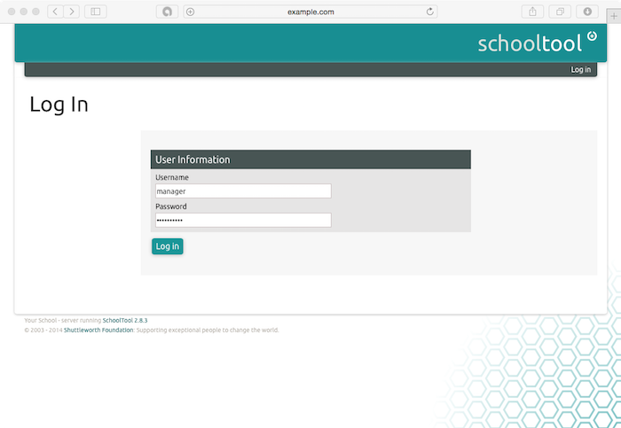
We should also be able to access the web UI at https://ipa.example.com.

Note: The TLS certificate will be untrusted. For now, we'll just bypass the warnings. In the future, you can use your favorite certificate authority to get a valid TLS certificate. Once you have it, you'll need to upload your CA certificate (usually ca.crt), certificate file (your_domain.crt), and key file ( your_domain.key) to the server.

Once you have the files, install the CA using the directory manager password you set earlier. You can precede the command with a space to prevent it from being saved to the shell history.
# ipa-cacert-manage -p your_directory_manager_password -n httpcrt -t C,, install ca.crt
Then install the site certificate and key.
# ipa-server-certinstall -w -d your_domain.key your_domain.crt
You will need to restart your server for these changes to take effect.

In the web UI, log in as the admin user. Username will be admin and Password will be the IPA admin password you set earlier. The top of the page will say Authenticating and then you will be brought to the main IPA page, which looks like this:


Finally, let's explore some of FreeIPA's features by adding a new user.


Configuring IPA Users

FreeIPA has a very extensive set of user management and policy features. Similar to standard Unix users, FreeIPA users can belong to groups. Either groups or individual users can be allowed or denied access to hosts (client machines) or groups of hosts (hostgroups) based on policies. FreeIPA can also manage sudo access; groups or users can be granted sudo access on hosts or host groups.

This guide will just go over how to add new users to get you started.

To add a user, click the Identity tab and click on Users. This will display a table of users. Click the + Add button above the table to add a new user. Fill in the required fields (like first and last name) in the form that opens, then click Add to add the user as is or Add and edit to configure advanced details.

The advanced details can also be accessed by clicking on the user in the original table. This is what an administrator sees when looking at a user's details:


Regular users can also log in to the IPA GUI. They will be able to view their own permissions and edit personal details.

New users will be asked to change their password the first time they log in to an IPA machine. This works in the IPA GUI as well as over SSH. One helpful feature is the ability to add SSH keys. A user can upload their public SSH keys and have them propagate out to the IPA machines, allowing passwordless login. The user can then remove the SSH key at any time without having to worry about it still being present on individual servers.


Conclusion

Since that you have a working FreeIPA server, you will need to configure clients to authenticate against it. Ubuntu and CentOS both have installer scripts for the FreeIPA client which allows them to be easily provisioned. In addition, FreeIPA is an LDAP server. Any service supporting LDAP authentication can be setup to authenticate against your FreeIPA server.

How To Set Up FreeIPA in a Mixed Environment (Windows/Linux)

$
0
0

This article is a practical step by step guide to implement freeIPA in mixed environment (Windows/Linux Clients). You should also refer the Installation and Deployment guide of FreeIPA directory server on CentOS 7 from the following link.


The Installation has been performed on the following environment.

Server: Single IPA server (Fedora 10 x86_64) with 2G RAM 1.6 GHz Intel Dual Core processor.
Clients: Windows XP SP2, Fedora 10 x86_64 and RHEL5.2 x86_64

Note: Please be careful about the firewall and selinux policies before continuing with the configuration. In windows also you should open the necessary ports to communicate to the IPA Server or disable the firewall if you are doing a test setup. Please refer the installation and deployment guide to get more details about the ports required for IPA.


1. Installation of the IPA Server.
# yum install ipa-*
# yum install bind bind-chroot
The IPA server may show a conflict with mod_ssl package. IPA uses mod_nss in apache. You can remove the mod_ssl for the time being.
2.Make sure that the host names are set properly
# cat /etc/hosts
127.0.0.1 localhost.localdomain localhost
172.16.33.1 ds.example.com ds
# cat /etc/sysconfig/network
NETWORKING=yes
HOSTNAME=ds.example.com
3. Run the following command to configure the IPA Server for you environment and follow the instructions.
# ipa-server-install --setup-bind
Here the DNS Server is on the same machine. Please note that kerberos server has very specific DNS requirements, if you have a DNS server already on your network add the SRV records of the kerberos, ntp and ldap server to that. A sample zone file will be created in your /tmp directory after the ipa-server-install, do a copy paste of all the SRV record from this file to your zone file.
If you have a chrooted bind installed, the named service start-up may fail after the ipa-server-install . Do the following configuration to setup DNS properly.
a. A minimal named.conf should look like
# cat /etc/named.conf
options {
directory "/var/named";
dump-file "data/cache_dump.db";
statistics-file "data/named_stats.txt";
memstatistics-file "data/named_mem_stats.txt";
};
zone "example.com" {
type master;
file "example.com.zone.db";
};
zone "33.16.172.in-addr.arpa" IN {
type master;
file "example.com.zone.rev.db";
};
b. Copy the zone file to the proper location and create a reverse zone file also.
# cp /var/named/example.com.zone.db /var/named/chroot/var/named/
No need to change anything in the forward zone file, create a reverse zone as follows.
#  cat example.com.zone.rev.db
$ORIGIN 33.16.172.in-addr.arpa.
$TTL 86400
@ IN SOA example.com. root.example.com. (
01  ; serial
3H  ; refresh
15M  ; retry
1W  ; expiry
1D )  ; minimum
IN NS                   ds.example.com.
1 IN PTR ds.example.com.
c. Restart the named service
4. Check whether the ntp time synchronization is proper, if you don't want to sync to an external time server, configure a local time server and synch all the clients to that.
# ntpstat
# ntpq -p
Sample configuration file for an ntp local server.
# cat /etc/ntp.conf
restrict default nomodify notrap noquery
restrict 127.0.0.1
broadcast 224.0.1.1 ttl 4
broadcastdelay 0.004
server  127.127.1.0
fudge 127.127.1.0 stratum 10
driftfile /var/lib/ntp/drift
keys /etc/ntp/keys
Sample Configuration for an ntp client
# cat /etc/ntp.conf
restrict default kod nomodify notrap nopeer noquery
restrict -6 default kod nomodify notrap nopeer noquery
restrict 127.0.0.1
restrict -6 ::1
server ds.example.com
driftfile /var/lib/ntp/drift
keys /etc/ntp/keys
Please note that if the client time has much difference compared to ntp server then do a force update using the following command. Also, the first time synchronization will take some time (64 sec approx)
# ntpdate -u ds.example.com
To verify
# ntpstat
# ntpq -p
5. Make sure that all the required services are enabled in your run level and reboot the IPA server (krb5kdc, ntp, named, httpd, dirserv etc). This will be configured automatically when you run the ipa-server-install, anyway just do a second check.
6. After the reboot test the IPA server configuration using the following commands
# kinit admin
# klist
# ipa-finduser admin

Configuring Windows Client

Note: An alternative solution exists: Windows authentication against FreeIPA
1. Add the host records in DNS, both forward and reverse
2. Make sure that the client is synchronized to the ntp server.
3. On the IPA Server add the host principal and set the password for the xp client.
#  ipa-addservice host/bmdata01.example.com
# ipa-getkeytab -s ds.example.com -p host/bmdata01.example.com -e des-cbc-crc -k krb5.keytab.txt -P
4. On the Client (Windows XP)
a. Install Windows XP support tools (WindowsXP-KB838079-SupportTools-ENU.exe, this can be found on the Windows XP Media or download it from microsoft)
b. Create a user in Windows XP to map the kerberos principles (here it is ipauser)
c. Configure kerberos authentication as follows (go to Start - Programs - Windows Support Tools - Command Prompt )
C:> ksetup /setrealm EXAMPLE.COM
C:> ksetup /addkdc EXAMPLE.COM dc.example.com
C:> ksetup /setmachpassword (the same password you have set in IPA server)
C:> ksetup /mapuser * ipauser
d. Reboot the machine.
e. You will see "EXAMPLE.COM (Kerberos Realm)" in the windows logon drop down menu.
Note: CREATE A NEW USER ON THE IPA SERVER AND TRY TO LOGON TO THE WINDOWS CLIENT. WINDOWS WILL TELL YOU THAT THE PASSWORD HAS BEEN EXPIRED. IT WILL PROMPT YOU TO SET THE NEW PASSWORD ALSO. IF YOU ENTER YOUR USER NAME, OLD PASSWORD AND NEW PASSWORDS, WINDOWS WILL SIMPLY TELL YOU "DOMAIN NOT AVAILABLE
HERE IS THE TRICK, PLEASE NOTE THAT THE USER IS REQUIRED TO LOGIN USING “USER@REALM” (testuser@EXAMPLE.COM) INSTEAD OF JUST THE USER NAME FOR THE FIRST TIME.

Configuring RHEL 5.2 x86_64 Client


1. Download and un-compress freeipa source, http://freeipa.org/downloads/src/freeipa-1.2.1.tar.gz
# tar -zxvf freeipa-1.2.1.tar.gz
# cd freeipa-1.2.1
2. Install the following prerequisites
# yum install autoconf automake pkgconfig.x86_64 libtool.x86_64 mozldap-devel.x86_64 krb5-devel.x86_64 openldap-devel.x86_64 python-ldap.x86_64
3. You will also need to downloaded and install python-krbV package from http://download.fedora.redhat.com/pub/epel/
4. Apply the patch
# patch -p1 < /path/to/make.patch 
(patch can be found in https://www.redhat.com/archives/freeipa-users/2009-January/msg00022.html, copy the contents and save it as make.patch)


5. Make rpms, the rpms will be in dist/rpms
# make IPA_VERSION_IS_GIT_SNAPSHOT=no local-dist

How To Monitor Datacenter Temperature with Nagios

$
0
0

This article will walk you through the steps to set up environmental monitoring sensor inside the datacenter to monitor temperature and humidity with Nagios.


Buy and Set Up Sensor

First you need to buy an environmental monitoring sensor from the eesensor and they ship it as quickly as possible. You will need to setup the sensor with a static IP address when you have it in hand. Also in the package box you will find an instruction manual of how to configure it. After you have the sensor setup with static IP address of your network, you will be able to login to the device by accessing the IP address on any of your favorite web browser.

This would be first screen you will see after login into the sensor.


Configure Nagios

First you need to download the nagios plugin from this URL and extract it in your nagios server. Copy the check_em01.pl to your Nagios plugin directory /usr/local/nagios/libexec and make the file executable using the chmod x+ check_em01.pl  command. There is also a Perl folder, inside the downloaded directory of nagios plugin and in that folder you will find checkcommands.cfg file. Edit it with any of your favorite editor and copy its contents to your Nagios commands.cfg file as show below.

# 'check_temp' command definition

define command{
command_name check_temp
command_line $USER1$/check_em01.pl --type=temp --temp=$ARG1$,$ARG2$ $HOSTADDRESS$
}

# 'check_humidity' command definition
define command{
command_name check_humidity
command_line $USER1$/check_em01.pl --type=hum --hum=$ARG1$,$ARG2$ $HOSTADDRESS$
}
Now setup the
# 'check_light command definition
define command{
command_name check_light
command_line $USER1$/check_em01.pl --type=illum --illum=$ARG1$,$ARG2$ $HOSTADDRESS$
}
Now setup the host and check up services. It will be look similar to like below:
define host{                                              
use websensor-host ; Name of host template to use
host_name websensor
alias websensor
address 192.168.x.x
contact_groups admins ;
}


define service{
use websensor-service ; Name of service template to use
host_name websensor
service_description EM01 Websensor Temperature
check_command check_temperature!20!80!10!88
}

define service{
use websensor-service ; Name of service template to use
host_name websensor
service_description EM01 Websensor Humidity
check_command check_humidity!10!90!5!95
}


Now reload Nagios with sudo service nagios reload command to update changes. The sensor should show up in your Nagios Dashboard as shown in image below.


Completed.

Difference Between DRP and BCP

$
0
0

Disaster Recovery Plans (DRP) is comprehensive statement of actions to be taken before, during and after a disruptive event causes loss of availability of Information Systems. Primary objective is to provide an alternate processing site and return to primary site within a minimal time frame when ever any disaster occurs in the information systems. Whereas the Business Continuity Plans (BCP) suggests a more comprehensive approach to deal with the restoration of computer systems with all attendant software and connections to full functionality under a variety of damaging or interfering external conditions that businesses face from time to time.


Difference Between DRP and BCP Explained

The differences between Disaster Recovery Plans and Business Continuity Plans are not very clear in actual usage. Different companies sometimes use these terms differently and, at times, interchangeably.

Technically the Business Continuity Plan (BCP) refers to the means by which loss of business may be avoided and it ought to define the business requirements for continuity of operations. It defines the business requirements for a Disaster Recovery Plan (DRP).

Technically, the Disaster Recovery Plan (DRP) deals with the restoration of computer systems with all attendant software and connections to full functionality under a variety of damaging or interfering external conditions. In daily practice Business Continuity often refers to disaster recovery from a business point-of-view, or dealing with simple daily issues, such as a failed disk, failed server or database, possibly a bad communications line. It is often referred to as the measure of lost time in an application, possibly a mission critical application.

In daily practice Disaster Recovery often refers to major disruption, such as a flooded building, fire or earthquake disrupting an entire installation. The issue of Business Continuity certainly arises when Disaster Recovery is required.

In short we can say that Disaster Recovery Plans addresses the procedures to be followed during and after the loss where as BCP is the preemptive process put in place in preparation for the handling of a disaster.

What is the purpose of a Disaster Recovery Plan (DRP)?

The primary purposes of a Disaster Recovery Plan (DRP) are as following:

  • Prevention (pre-disaster): The pre-planning required — using mirrored servers for mission critical systems, maintaining hot sites, training disaster recovery personnel – to minimize the overall impact of a disaster on systems and resources. This pre-planning also maximizes the ability of an organization to recover from a disaster.
  • Continuity (during a disaster): The process of maintaining core, mission-critical systems and resource “skeletons” (the bare minimum assets required to keep an organization in operational status) and/or initiating secondary hot sites during a disaster. Continuity measures prevent the whole organization from folding by preserving essential systems and resources.
  • Recovery (post-disaster): The steps required for the restoration of all systems and resources to full, normal operational status. Organizations can cut down on recovery time by subscribing to quick-ship programs (third-party service providers

Who can deliver pre-configured replacement systems to any location within a fixed timeframe).

What are the key elements of a DRP?

The primary objective of Disaster Recovery Plan (DRP) is to enable an organization to survive a disaster and to continue normal business operations. In order to survive, the organization must assure that critical operations can resume/continue normal processing. Throughout the recovery effort, the plan establishes clear lines of authority and prioritizes work efforts.

The following key of Disaster Recovery Plan (DRP) should be to:

  • Provide for the safety and well-being of people on the premises at the time of a disaster;
  • Continue critical business operations;
  • Minimize the duration of a serious disruption to operations and resources (both information processing and other resources);
  • Minimize immediate damage and losses;
  • Establish management succession and emergency powers;
  • Facilitate effective co-ordination of recovery tasks;
  • Reduce the complexity of the recovery effort;
  • Identify critical lines of business and supporting functions;

Although statistically the probability of a major disaster is remote, the consequences of an occurrence could be catastrophic, both in terms of operational impact and public image. Management appreciates the implications of an occurrence; therefore, it should assign on-going responsibility for recovery planning to an employee dedicated to this essential service.

Management must make a decision to undertake a project that satisfies the following objectives:

  • Determine vulnerability to significant service interruptions in the Data Centre and business facilities and define preventive measures that may be taken to minimize the probability and impact of interruptions;
  • Identify and analyze the economic, service, public image and other implications of extended service interruptions in the Data Centre and other business facilities;
  • Determine immediate, intermediate and extended term recovery needs and resource requirements;
  • Identify the alternatives and select the most cost effective approaches for providing backup operations capability and timely service restoration; and
  • Develop and implement contingency plans that address both immediate and longer-term needs for the Data Centre and other business facilities.


What are the five methods of testing a DRP?

There are several different types of testing method are available to test the Disaster Recovery Plan which can be used when testing a DRP. The following five methods are mostly used methods in this field of DRP testing, which are as following:

  • Walkthrough Testing
  • Simulation Testing
  • Checklist Testing
  • Full Interruption Testing and
  • Parallel Testing


Many companies decide to go ahead with a checklist to then proceed to a simulation test. The simulation test is important so that employees know what to do when a disaster actually occurs. The company may decide to do a full interruption test while doing a simulation test, but that really depends on if the company has the type of budget that will allow for this type of testing.


Why does a DRP require testing?

The key objectives of a DRP testing are as following:
  • Exercise the recovery processes and procedures
  • Familiarize staff with the recovery process and documentation;
  • Verify the effectiveness of the recovery documentation;
  • Verify the effectiveness of the recovery site;
  • Establish if the recovery objectives are achievable;
  • Identify improvements require to the DR strategy, infrastructure, and recovery processes


So, DRP testing is required to test these key objectives and ensuring that our Disaster Recovery Plan will be work at the time of any disaster occurs.


This article was originally published at disaster recovery plan template

How To Migrate VMFS 5 Datastore to VMFS 6 Datastore

$
0
0

This guide provides information on migrating existing vSphere VMFS 5 datastore to vSphere VMFS 6 datastore.


VMFS 6 is the new filesystem of vSphere 6.5. The new filesystem supports 512e advanced format drives and is 4098 sector (4K) aligned. It also supports automatic UNMAP, which asynchronously tracks freed blocks and sends UNMAPs to backend storage in background.

VMFS 5 and VMFS 6 can coexist. However, due to the changes done in VMFS 6 metadata structures to make it 4K aligned, you cannot inline/offline upgrade from VMFS5 to VMFS6.

You can leverage the new VMFS 6 capabilities by creating a new VMFS 6 datastore and provisioning new virtual machines to it or migrating the existing virtual machines from VMFS 5 datastore to VMFS 6 datastore.

Prerequisites

In this KB we are assuming that vSphere admins are upgrading their VMFS datastores one at a time. The below description applies mostly to these scenarios. Though the basic workflow will not change if someone wants to perform upgrade of multiple datastores in parallel. 
Keep the following info handy while you plan for your VMFS datastore upgrade:
  • Identify the VMFS datastore that must be upgraded to VMFS 6 file system type. For example, DS-1.
  • Identify the name of the vCenter Server and list of all ESX hosts sharing the datastore with credentials.
  • All ESX hosts and the vCenter server must be upgraded to vSphere 6.5.


Note: Do not proceed with datastore upgrade until all ESX hosts which share the datastore are upgraded to vSphere 6.5. If you do not upgrade, older ESX hosts lose connectivity to the new VMFS 6 datastore after upgrading. This may impact the business continuity.

  • Spare datastore with equal or more capacity, which is shared with all ESX hosts. For example, DS-2 in this KB. The DS-2 datastore is used to temporarily host all virtual machines from the DS-1 datastore.


Requirements when you are automating the process using windows powershell scripts:

  • Windows 2008/2008 R2/2012 on 64bit in a domain environment. The windows host used for launching the utility.
  • PowerShell 2.0 or above, with all policies set. vSphere powershell plugins installed. Should be able to launch as Administrator. Execute in 64bit PowerShell environment.


Different deployment use cases and migration steps

Note: You can directly migrate your virtual machines from VMFS 5 datastores to VMFS 6 datastores using Storage vMotion. However, below is the recommended process for different deployment scenarios.


Usecase 1: One vCenter Server having inventory of registered virtual machines running from datastore DS-1.

The DS-1 datastore of VMFS 5 (or VMFS 3) must be upgraded to datastore with filesystem type VMFS 6.  This datastore is shared with all the ESX hosts in the inventory and has some virtual machines running from this datastore.

To upgrade:

  • Perform version check for the vCenter Server and all ESX hosts.


Note: All ESXi hosts and vCenter Server must be of vSphere 6.5. Do not proceed if any one of ESXi hosts is not vSphere 6.5. Proceeding further means business continuity loss and the new datastore is not visible in old ESX hosts.

  • Perform all pre checks for free space availability on datastore DS-2.  Available space on DS-2 must be equal or more than the datastore DS-1 space.
  • Ensure that the datastore DS-2 is VMFS 5 type.
  • Prepare list of all virtual machines in the vCenter Server’s inventory that are hosted on datastore DS-1.
  • Evacuate the datastore DS-1. For this, migrate all the virtual machines running from datastore DS-1 to datastore DS-2. Storage vMotion operations are performed on these virtual machines.

  • Perform one migration at a time to avoid disrupting the performance of remaining datacenter entities. Keep track of any migration failures, if any, re-trigger the migration for those virtual machines. 

  • Ensure that datastore DS-1 is empty by listing files on this datastore.


Note: Proceed further only if datastore DS-1 is empty.

  • Unmount datastore DS-1 from all ESX hosts.
  • Delete datastore DS-1.
  • Create a new datastore with the VMFS 6 filesystem using the same lun. For example, DS-1.
  • Trigger a storage rescan operation on all hosts and wait for few minutes for this operation to complete.
  • Move all virtual machines back to datastore DS-1 from datastore DS-2 by performing storage vMotion operation. It is suggested to migrate one virtual machine at a time. Keep track of any migration failures, if any, re-trigger migration for those virtual machines.
  • Note: If you have Storage DRS configured in this environment and you are using SDC, you can also use datastore maintenance mode feature to aid in the above steps. See Usecase 5 for more information.

Usecase 2: One vCenter Server having inventory of registered virtual machines running from datastore DS-1. Datastore DS-1 also has some orphaned data which is not registered in the vCenter Server’s inventory.

To upgrade:

  • Perform version check for vCenter Server and all ESX hosts.

Note: All ESXi hosts and vCenter Server must be of vSphere 6.5. Do not proceed if any one of ESXi hosts is not vSphere 6.5. Proceeding further means business continuity loss and the new datastore is not visible in old ESX hosts.

  • Perform all pre checks for free space availability on datastore DS-2. Available space on DS-2 must be equal or more than the datastore DS-1 space.
  • Ensure that the datastore DS-2 is VMFS 5 type.
  • Prepare list of all virtual machines in the vCenter Server’s inventory that are hosted on datastore DS-1.
  • Evacuate the datastore DS-1. For this, migrate all the virtual machines running from datastore DS-1 to datastore DS-2. Storage vMotion operations are performed on these virtual machines. 
Perform one migration at a time to avoid disrupting the performance of remaining datacenter entities. Keep track of any migration failures, if any, re-trigger the migration for those virtual machines.
  • Prepare the list of files (orphaned files, not registered to the vCenter Server’s inventory) present on datastore DS-1.
  • Start moving these files to datastore DS-2 one at a time. It is suggested to use one of the recommended ways to move files on VMFS datastores. 

For example, vmkfstools utility on ESX commandline, powershell cmdlets. 

  • Ensure that datastore DS-1 is empty by listing files on this datastore. Proceed further only if datastore DS-1 is empty.
  • Unmount datastore DS-1 from all the ESX hosts.
  • Delete datastore DS-1.
  • Create a new datastore with the VMFS 6 filesystem using the same lun. For example, DS-1.
  • Trigger a storage rescan operation on all hosts and wait for few minutes for this operation to complete.
  • Move all virtual machines back to datastore DS-1 from datastore DS-2 by performing storage vMotion operation. It is suggested to migrate one virtual machine at a time. Keep track of any migration failures, if any, re-trigger migration for those virtual machines.
  • Move orphaned data files back to datastore DS-2 one at a time. It is suggested to use one of the recommended ways to move files on VMFS datastores. 

For example, vmkfstools utility on ESX commandline, powershell cmdlets.

Note: You cannot use Storage DRS and SDC reliably in this case because datastore maintenance operation evacuates a datastore with known virtual machine objects only. For example, virtual machines that are registered to the vCenter Server’s inventory. Any other data on the datastore is left behind.

Usecase 3: One vCenter Server having inventory of registered virtual machines running from datastore DS-1. Datastore DS-1 has some virtual machines configured with virtual disk affinity rules.

To upgrade:

  • Perform version check for vCenter Server and all ESX hosts.

Note: All ESXi hosts and vCenter Server must be of vSphere 6.5. Do not proceed if any one of ESXi hosts is not vSphere 6.5. Proceeding further means business continuity loss and the new datastore is not visible in old ESX hosts.


  • Perform all pre checks for free space availability on datastore DS-2. Available space on DS-2 must be equal or more than the datastore DS-1 space.
  • Ensure that the datastore DS-2 is VMFS 5 type.
  • Prepare list of all virtual machines in the vCenter Server’s inventory that are hosted on datastore DS-1.
  • Identify virtual machines and virtual disks that are configured for disk affinity rules and are hosted from datastore DS-1. If automatic storage load balancing is configured in the cluster, change it to manual setting. Make a note of all the storage affinity rules currently configured.
  • Evacuate the datastore DS-1. For this, migrate all the virtual machines running from datastore DS-1 to datastore DS-2. Storage vMotion operations are performed on these virtual machines. 

Perform one migration at a time to avoid disrupting the performance of remaining datacenter entities. Keep track of any migration failures, if any, re-trigger the migration for those virtual machines.

  • Ensure that datastore DS-1 is empty by listing files on this datastore. Proceed further only if datastore DS-1 is empty.
  • Unmount the datastore DS-1 from all ESX hosts.
  • Delete the datastore DS-1.
  • Create a new datastore with the VMFS 6 filesystem using the same lun. For example, DS-1.
  • Trigger a storage rescan operation on all hosts and wait for few minutes for this operation to complete.
  • Add this datastore back to datastore cluster as earlier.
  • Move all virtual machines back to datastore DS-1 from datastore DS-2 by performing storage vMotion operation. It is suggested to migrate one virtual machine at a time. Keep track of any migration failures, if any, re-trigger migration for those virtual machines.
  • Add all the storage affinity rules back as earlier (from step #5). If automatic storage load balancing is configured in the cluster, change it back to the original setting (automatic mode). 
Note: If you have Storage DRS configured in this environment and you are using SDC, you can also use datastore maintenance mode feature to aid in the above steps. See Usecase 5 below for more detailed description on this.

Usecase 4: One vCenter Server having inventory of registered virtual machines running from datastore DS-1. Datastore DS-1 has some virtual machines with multiple virtual disks attached. At least one of these virtual disks for these virtual machines is hosted from datastore DS-1.

To upgrade:

  • Perform version check for vCenter Server and all ESX hosts.

Note: All ESXi hosts and vCenter Server must be of vSphere 6.5. Do not proceed if any one of ESXi hosts is not vSphere 6.5. Proceeding further means business continuity loss and the new datastore is not visible in old ESX hosts.

  • Perform all pre checks for free space availability on datastore DS-2. Available space on DS-2 must be equal or more than the datastore DS-1 space.
  • Ensure that the datastore DS-2 is VMFS 5 type.
  • Prepare list of all virtual machines in the vCenter Server’s inventory that are hosted on datastore DS-1.
  • Evacuate the datastore DS-1. For this, migrate all the virtual machines running from datastore DS-1 to datastore DS-2. Storage vMotion operations are performed on these virtual machines. 

Perform one migration at a time to avoid disrupting the performance of remaining datacenter entities. Keep track of any migration failures, if any, re-trigger the migration for those virtual machines.

  • In virtual machines with multiple virtual disks, in which atleast one disk hosted from datastore DS-1. Migrate only these particular virtual disks to datastore DS-2. Keep a list of such virtual machines and virtual disks.
  • Ensure that datastore DS-1 is empty by listing files on this datastore. Proceed further only if datastore DS-1 is empty.
  • Unmount datastore DS-1 from all ESX hosts.
  • Delete datastore DS-1.
  • Create a new datastore with the VMFS 6 filesystem using the same lun. For example, DS-1.
  • Trigger a storage rescan operation on all hosts and wait for few minutes for this operation to complete.
  • Move all virtual machines back to datastore DS-1 from datastore DS-2 by performing storage vMotion operation. It is suggested to migrate one virtual machine at a time. Keep track of any migration failures, if any, re-trigger migration for those virtual machines.
  • Migrate virtual disks identified in step # 6 back to datastore DS-1.

Usecase 5: One vCenter Server having inventory of registered virtual machines running from datastore DS-1. Storage DRS is being used and datastore DS-1 is part of Storage Datastore Cluster (SDC). Automatic load balancing features are turned ON for space and IO load balancing in this SDC.
This is the usecase with one vCenter Server in the environment. The datastore DS-1 is of type VMFS 5 (or VMFS 3) and must be upgraded to datastore with filesystem type VMFS 6. The vCenter Server is also configured with Storage DRS. There is a Storage Datastore Cluster (SDC) created and datastore DS-1 is part of this datastore cluster. This datastore cluster is also configured to have storage space and IO load balancing in fully automatic mode.

To upgrade:

  • Perform version check for vCenter Server and all ESX hosts.

Note: All ESXi hosts and vCenter Server must be of vSphere 6.5. Do not proceed if any one of ESXi hosts is not vSphere 6.5. Proceeding further means business continuity loss and the new datastore is not visible in old ESX hosts.

  • Perform all pre checks for free space availability on datastore DS-2. Available space on DS-2 must be equal or more than the datastore DS-1 space.
  • Ensure that the datastore DS-2 is VMFS 5 type and is empty.
  • Add datastore DS-2 to this datastore cluster.
  • Put datastore DS-1 into maintenance mode. This should start evacuating datastore DS-1 with storage vMotion operations on the virtual machines. You also observe some of virtual machine moving towards datastore DS-2.
  • Ensure that datastore DS-1 is empty by listing files on this datastore. Proceed further only if datastore DS-1 is empty.
  • Unmount datastore DS-1 from all ESX hosts.
  • Delete datastore DS-1.
  • Create a new datastore with the VMFS 6 filesystem using the same lun. For example, DS-1.
  • Trigger a storage rescan operation on all hosts and wait for few minutes for this operation to complete.
  • Add datastore DS-1 back to the Storage Datastore Cluster.
  • Put datastore DS-2 into maintenance mode. This starts evacuating datastore DS-2 with Storage vMotion operations on the virtual machines.
  • Move the datastore DS-2 out of the datastore cluster.
  • Exit maintenance mode for datastore DS-2.

Usecase 6: The vCenter Server is having inventory of registered virtual machines running from datastore DS-1. At least one ESX server which also has inventory of registered virtual machines running from the same datastore DS-1. This ESX server is not added to any vCenter Server’s inventory.
One vCenter Server in the environment. The datastore DS-1 is of type VMFS 5 (or VMFS 3) and must to be upgraded to datastore with filesystem type VMFS 6.  This datastore is shared with all the ESX hosts in the vCenter inventory and has some virtual machines running from this datastore. Additionally, this datastore is also shared with at least one ESX host. This ESX host is not added to vCenter Server inventory. There are some virtual machines running from this ESX host and datastore DS-1.  Let us call this ESX host as ESX-1 in below steps.

To upgrade:

  • Perform version check for vCenter Server and all ESX hosts.

Note: All ESXi hosts and vCenter Server must be of vSphere 6.5. Do not proceed if any one of ESXi hosts is not vSphere 6.5. Proceeding further means business continuity loss and the new datastore is not visible in old ESX hosts.

  • Perform version check for ESX server EWSX-1. This ESX host must be vSphere 6.5.

Note: Do not proceed if any one of ESXi hosts is not vSphere 6.5. 

  • Perform all pre checks for free space availability on datastore DS-2. Available space on DS-2 must be equal or more than the datastore DS-1 space.
  • Ensure that the datastore DS-2 is of VMFS 5 type.
  • Ensure that the datastore DS-2 is visible from host ESX-1.
  • Add ESX-1 to the vCenter Server inventory.
  • Prepare the list of virtual machines in the vCenter Server’s inventory that are hosted on datastore DS-1.
  • Prepare list of virtual machines running from ESX server ESX-1 and hosted on datastore DS-1.
  • Evacuate the datastore DS-1. For this, migrate all the virtual machines running from datastore DS-1 to datastore DS-2 by performing storage vMotion operations on these virtual machines. 

Perform one migration at a time to avoid disrupting the performance of remaining datacenter entities. Keep track of any migration failures, if any, re-trigger the migration for those virtual machines.

  • Ensure that datastore DS-1 is empty by listing files on this datastore. Proceed further only if datastore DS-1 is empty.
  • Unmount datastore DS-1 from all ESX hosts.
  • Delete datastore DS-1.
Note: You may have other deployment situations which may require you to take some extra precautions while doing this migration. Attached to this article is the 2147824_SampleMigrationVMFS5ToVMFS6.ps1 script. Ensure that you understand your environment and perform migration steps accordingly.
 Attached is a sample script name “2147824_SampleMigrationVMFS5ToVMFS6.ps1".


The contents of the article was taken from VMware Knowledge Base

Migrating Windows Installation to a Solid-State Drive

$
0
0

This guide walks you through the steps to migrate your Windows 7, 8, or 10 installation to an SSD without reinstalling Windows. 


Prerequisites

You'll need a copy of EaseUS Todo Backup. Its free version has all the features we need to accomplish the task, so download the free version and install it like you would any other Windows program.

If you have a desktop computer, then you can usually just install your new SSD alongside your old hard drive in the same machine to clone it. If you’re using a laptop, however, this usually isn’t possible, so you’ll need to buy something like a SATA-to-USB cable (shown in image below), which will let you connect a 2.5″ hard drive or SSD to your laptop via USB. You can also install your SSD in an external hard drive enclosure before you start the migration process.


STEP1 - Verify Hard Drives Space

To check the capacity of each drive, plug your SSD into your computer and wait for it to visible in Windows Explorer. Right-click on each drive and select “Properties”.

Here you can see that, our existing hard disk used space is large than the newly attached SSD. If you experience similar to this then before you migrate your data, you’ll need to clean up your current hard drive by deleting unwanted or unnecessary data. 


STEP2 - Update SSD’s Firmware

To update firmware, visit the the website of your solid state drive manufacturer to download and update the firmware. Now is the absolute perfect time to update the firmware as there is zero risk of data loss, since you haven’t copied anything to it yet. 


STEP3 - Clone Drive With EaseUS Todo Backup

Finally its time to start migrating process. Open up the EaseUS application and click “Clone” on the main screen.


First, select your source disk. This will be  your current Windows system drive. Our current disk drive comprises of three partitions: an active boot partition, the actual Windows partition, and a recovery partition. We want to clone all three, so we’re just going to place a check next to the hard disk to make sure they’re all selected. Click “Next” to proceed.


Now you need to select your SSD as the destination. Make sure you choose the correct drive, or you could lose data!

Tick it, and then check the “Optimize for SSD” box, which will ensure you get the best performance possible out of your resulting Windows installation.


Now, before you click “Next”, take a moment to click the “Edit” button next to your SSD.


EaseUS will show you what your resulting drive will look like. In some cases, you may need to do some additional steps here. For instance, on my SSD, EaseUS wanted to make the boot and recovery partitions much larger, even though they contain less than a gigabyte of data. I’d rather have that space on my main Windows partition, so I needed to resize these before continuing.


To resize these partitions, first select one, then drag the handles that appear between the partitions, much as if you were resizing a File Explorer window.


Then resize main Windows partition to fill the rest of the empty space.


Depending on your drive’s layout, you may have to alter things in a different way. When you’re done, click “OK” to continue. Double-check that everything looks right, and click “Proceed” to start the clone operation.


If you get the following warning, click “OK” to continue.


The actual length of the operation will depend on how large your source drive is, as well as the speed of the storage mediums and your computer. For me, it took about 15 minutes.


When the operation is completed, click “Finish”.

As you can see in the following image , our new system drive is already visible in File Explorer. All that’s left now is to begin using it.


To accomplish this, the next steps are pretty simple. Shut down your computer, remove the old drive and install the new in the same slot. Restart your computer and it should boot from your new drive automatically.

Make sure TRIM is turned on. TRIM is a special set of commands that help SSDs effectively manage empty space on the disk (if you’re curious you can read more here). Open up the command prompt and execute the following command:

fsutil behavior query DisableDeleteNotify

This lengthy command has a very simple output, either a 0 or a 1. If you get a 1, TRIM is not enabled. If you get a 0, TRIM is enabled. If you need to enable it execute the following command:

fsutil behavior set DisableNotify 0

Make sure defragmentation is turned off. There is no need to defragment an SSD, and in fact, it’s advisable not to. Windows should handle this automatically, but it doesn’t hurt to check. Open the Start menu and, in the run box, type dfrgui to open the Disk Defragmenter. Click on the Schedule button, then click “Select Disks” Uncheck your SSD (which should be your C: drive) and Click OK.

If you want, you can even point your special user folders to that new location, so Windows will always look there first for the files. Just right-click on your Documents, Music, or other user folders and head to Properties > Location > Move… to move them.


You are done.

How to Create UEFI Bootable USB Media to install Windows Server 2016

$
0
0

This guide walks you through the steps to create a bootable usb media to install Windows Server 2016 on UEFI enabled machines. I have configured the BIOS settings of the server to only boot UEFI and disabled the legacy boot.


Prerequisites


  • A USB stick with more than 5.3GB is required
  • UEFI requires a FAT32 partition
  • FAT32 has some serious limitations and the size of the install.wim file exceeds those limits. This file requires therefore to be split into multiple more suitable parts

You can create USB boot media compatible with UEFI using PowerShell with the following script.
# Set here the path of your Win2K16 ISO file
$iso = 'C:\Users\
username\Downloads\en_windows_server_2016_x64_dvd_9327751.iso'

# Clean ! will clear any plugged-in USB stick!!
Get-Disk | Where BusType -eq 'USB' |
Clear-Disk -RemoveData -Confirm:$true -PassThru

# Convert GPT
if ((Get-Disk | Where BusType -eq 'USB').PartitionStyle -eq 'RAW') {
Get-Disk | Where BusType -eq 'USB' |
Initialize-Disk -PartitionStyle GPT
} else {
Get-Disk | Where BusType -eq 'USB' |
Set-Disk -PartitionStyle GPT
}

# Create partition primary and format to FAT32
$volume = Get-Disk | Where BusType -eq 'USB' |
New-Partition -UseMaximumSize -AssignDriveLetter |
Format-Volume -FileSystem FAT32

if (Test-Path -Path "$($volume.DriveLetter):\") {

# Mount iso
$miso = Mount-DiskImage -ImagePath $iso -StorageType ISO -PassThru

# Driver letter
$dl = ($miso | Get-Volume).DriveLetter
}

if (Test-Path -Path "$($dl):\sources\install.wim") {

# Copy ISO content to USB except install.wim
& (Get-Command "$($env:systemroot)\system32\robocopy.exe") @(
"$($dl):\",
"$($volume.DriveLetter):\"
,'/S','/R:0','/Z','/XF','install.wim','/NP'
)

# Split install.wim
& (Get-Command "$($env:systemroot)\system32\dism.exe") @(
'/split-image',
"/imagefile:$($dl):\sources\install.wim",
"/SWMFile:$($volume.DriveLetter):\sources\install.swm",
'/FileSize:4096'
)
}

# Eject USB
(New-Object -comObject Shell.Application).NameSpace(17).
ParseName("$($volume.DriveLetter):").InvokeVerb('Eject')

# Dismount ISO
Dismount-DiskImage -ImagePath $iso


That's it.

Installing Windows Server Update Services (WSUS) 2016

$
0
0

This article demonstrates the installation and configuration steps of WSUS on Windows Server 2016. The thing you need to consider is enough disk space to store updates before starting the installation process.


To begin the process, open up Server Manager and add the new server. Right-click All Servers and select “Add Servers.” Enter the name of the new server.


Select the Server and Click OK. In Server Manager, click “Manage” then “Add Roles and Features.” If you see a “Before You Begin” page, click Next.

Select a Role-based installation.


Select your server in the list


Select the Windows Server Update Services role, Click Next


You’ll be prompted to install other required features, such as different IIS features. Go ahead and install those as well.

The next page will show you Windows features to be installed. Do not uncheck anything here, as some of the items were enabled to support the WSUS installation. Click Next.


Here you’ll see a summary of related WSUS services. I’m going to use the Windows Internal database for WSUS, so I’ll leave this as-is and click Next.


Specify the location for the downloaded updates. Make sure you have enough disk space. Click Next


I’ll accept the defaults. Click Next


Confirm your selection and click Install


Installation process started.


Don't forget to export configuration settings for later use.

Once installation complete, reboot your server.

Once reboot complete, Open up Server Manager, WSUS, Click More

Click  "Launch Post-Installation tasks"


Depends on your environment whether you want to configure SSL or not. Click Connect


Start configuring your WSUS post installation tasks as they are self explanatory.


That's it.

How To Deploy Active Directory Federation Services on Windows Server 2016

$
0
0

Active Directory Federation Services provides access control and single sign on across a wide variety of applications including Office 365, cloud based SaaS applications, and applications on the corporate network. 


  • For the IT organization, it enables you to provide sign on and access control to both modern and legacy applications, on premises and in the cloud, based on the same set of credentials and policies.
  • For the user, it provides seamless sign on using the same, familiar account credentials.
  • For the developer, it provides an easy way to authenticate users whose identities live in the organizational directory so that you can focus your efforts on your application, not authentication or identity.

AD FS 2016 enables three new options for sign on without passwords, enabling organizations to avoid risk of network compromise from phished, leaked or stolen passwords.


Sign in with Azure Multi-factor Authentication

AD FS 2016 builds upon the multi-factor authentication (MFA) capabilities of AD FS in Windows Server 2012 R2 by allowing sign on using only an Azure MFA code, without first entering a username and password.

  • With Azure MFA as the primary authentication method, the user is prompted for their username and the OTP code from the Azure Authenticator app.
  • With Azure MFA as the secondary or additional authentication method, the user provides primary authentication credentials (using Windows Integrated Authentication, username and password, smart card, or user or device certificate), then sees a prompt for text, voice, or OTP based Azure MFA login.
  • With the new built-in Azure MFA adapter, setup and configuration for Azure MFA with AD FS has never been simpler.
  • Organizations can take advantage of Azure MFA without the need for an on premises Azure MFA server.
  • Azure MFA can be configured for intranet or extranet, or as part of any access control policy.


Password-less Access from Compliant Devices

AD FS 2016 builds on previous device registration capabilities to enable sign on and access control based the device compliance status. Users can sign on using the device credential, and compliance is re-evaluated when device attributes change, so that you can always ensure policies are being enforced. This enables policies such as

  • Enable Access only from devices that are managed and/or compliant
  • Enable Extranet Access only from devices that are managed and/or compliant
  • Require multi-factor authentication for computers that are not managed or not compliant
  • AD FS provides the on premises component of conditional access policies in a hybrid scenario. When you register devices with Azure AD for conditional access to cloud resources, the device identity can be used for AD FS policies as well.


Sign in with Microsoft Passport


Windows 10 devices introduce Windows Hello and Microsoft Passport for Work, replacing user passwords with strong device-bound user credentials protected by a user's gesture (a PIN, a biometric gesture like fingerprint, or facial recognition). AD FS 2016 supports these new these new Windows 10 capabilities so that users can sign in to AD FS applications from the intranet or the extranet without the need to provide a password.


This guide walks you through the the steps to installing and configuring the Active Directory Federation Services (AD FS) server role on Windows Server 2016. 


Installing Active Directory Federation Services Role

To begin, Open up Server Manager and click Manage click Add Roles and Features:


Click Next:


Role-based or feature-based installation should be selected then click Next:

Select the server you want to install this role then click Next:
Note: Web Application Proxy role and AD FS cannot be installed on the same computer.

Select Active Directory Federation Services then click Next:

No additional Features are needed. Click Next:


Click Next:

The AD FS role does not required a reboot. Click Install:

Once complete click Close:


Post-deployment Configuration

Back on Server Manager under Notifications click the message Configure the federation service on this server:


Since this is our first AD FS server select the first option then click Next:

Ensure the account you are logged into has Active Directory Domain Admin permissions. If not then click Change. Click Next to continue:


SSL Certificate: On the drop down menu you will see the certificates installed on the server. You can use the default self signed or use one you create. Make sure you have it in .pfx format.
Federation Service Name: Give your AD FS a FQDN name.
Federation Service Display Name: Enter a display name
Click Next to proceed:

Note about Federation Service Name: If you are installing AD FS on a Domain Controller or want to use a different FQDN for AD FS than the server you will need to ensure the name you enter has a DNS Record created.
Since this is my test lab I am adding  AD FS on my Domain Controller and needed to create a DNS entry

Note about SSL Certificate: If you imported a certificate you will see it added to your Personal Certificates.

On the Specify Service Account tab you may get the following message:
If you want the Wizard to create a Service Account for you then proceed to the PowerShell window below. If you want to create a Service Account manually you can add it by selecting the second option.

To get more info about the command 
Get-Help Add-KdsRootKey 
To generate root key    
Add-KdsRootKey -EffectiveImmediately 

Enter the Service Account you want to use and click Next:
Note: Ensure this user account is added to the local administrators group of your AD FS server. It is required to setup Microsoft Web Application Proxy.

You have the option of using a Windows Internal Database (WID) or SQL Server. If you have a small environment/lab then use WID. If you have a large environment use a SQL database. Click Next:
Note: WID is a limited version of SQL Express that doesn’t have a GUI or management interface. The WID database is a file (SUSDB.dbf) stored in C:\Windows\wid\data\

Click Next:

If everything fine click Configure:

Once complete click Close

Active Directory Federation Services is now installed and is ready for testing.

Open up a web browser and navigate to the URL https://ADFS-FQDN/adfs/ls/ldpintiatedSignOn and click Sign In:


Enter your domain credentials, once logged in, the following page will show up

That's it.

How To Deploy Web Application Proxy on Windows Server 2016

$
0
0

Microsoft Web Application Proxy was introduced in Windows Server 2012 R2. It allows you to access web applications from outside your network and it acts as a reverse proxy and an Active Directory Federation Services proxy to pre-authenticate user access.


This guide walks you through the steps to install and configure web application proxy role on Windows Server 2016.

Web Application Proxy New Features

  • Preauthentication for HTTP Basic application publishing
  • HTTP Basic is the authorization protocol used by many protocols, including ActiveSync, to connect rich clients, including smartphones, with your Exchange mailbox. Web Application Proxy traditionally interacts with AD FS using redirections which is not supported on ActiveSync clients. This new version of Web Application Proxy provides support to publish an app using HTTP basic by enabling the HTTP app to receive a non-claims relying party trust for the application to the Federation Service.
  • Wildcard domain publishing of applications
  • To support scenarios such as SharePoint 2013, the external URL for the application can now include a wildcard to enable you to publish multiple applications from within a specific domain, for example, https://*.sp-apps.contoso.com. This will simplify publishing of SharePoint apps.
  • HTTP to HTTPS redirection
  • In order to make sure your users can access your app, even if they neglect to type HTTPS in the URL, Web Application Proxy now supports HTTP to HTTPS redirection.
  • HTTP Publishing
  • It is now possible to publish HTTP applications using pass-through preauthentication
  • Publishing of Remote Desktop Gateway apps
  • New debug log for better troubleshooting and improved service log for complete audit trail and improved error handling
  • Administrator Console UI improvements
  • Propagation of client IP address to backend applications

The following diagram explains the architectural layout of Web Application Proxy. 


Prerequisites

Web Application Proxy and Active Directory Federation Services can not be deployed on same server. You need an additional server to set up web proxy. We assume that the following services are already installed and configured accordingly.

Installing the Web Application Proxy Server Role

To begin, Open up Server Manager and click Manage click Add Roles and Features


Click Next:

Select Role-based or feature-based installation, click Next:

Select the server you want to install this role on to and then click Next:

Select Remote Access then click Next:

No additional Features are needed. Click Next:

Click Next:

Select Web Application Proxy:

On the pop up click Add Features

The Web Application Proxy role does not required a reboot. Click Install

Once complete click Close

Web Application Proxy is now installed but you need the AD FS certificate to continue.
You need the certificate from your AD FS server added to your Web Application Proxy server. Login to your AD FS server and open MMC.exe:

Go to File > Add/Remove Snap-ins > select Certificates then click Add:

When you click OK you will get the following pop up. Select Computer account then click Next:

On AD FS Server: Scroll down to Personal > Certificates then right click the SSL certificate you used during setup of AD FS. Go to All Tasks > Export. Save to a location that your Web Application Proxy can access. Make sure you export the Private Key and certificate as a .pfx file format.

On Web Application Proxy: Right click on Personal > Certificates then go to All Tasks > Import:

This will bring up the Certificate Import Wizard. Click Next


Browse to the certificate that you exported from your AD FS server and select it. Click Next

Enter the password for the private key and check the box to make the key exportable. Click Next

Leave the default certificate store as Personal. Click Next

Click Finish

You should now see the certificate from your AD FS servers on your Web Application Proxy server

Now you are ready to start the Post Configuration settings.
Back on your Web Application Server open Server Manager then click Notifications then the message Open the Web Application Proxy Wizard:

Click Next:

Enter the FQDN of your AD FS name and the Service Account you created during AD FS setup. Click Next: 

On the drop down menu select the certificate you imported from your AD FS server. Click Next

Click Configure


Once finished click Close


Remote Access Management Console should open when you clicked Close. On Operations Status you should see all the objects as green


Finally, its time to publish apps. In the Remote Access Management Console click Web Application Proxy then Publish


Click Next:

Pass-through will let WAP act like a reverse proxy. 
Here you have two options: (AD FS and Pass-through) self-explanatory. I have already set up AD FS in your environment then go with the first option otherwise 2nd is my choice since at the moment I don't have AD FS.
Select Pass-through and click Next

Name: Enter a display name
External URL: Enter the URL that will be coming in your the WAP server externally
External Certificate: The drop down menu will show certificates that are added on the WAP server. Select the same certificate that you used while setting up your application. In my case I used my wildcard certificate.
Backend server URL: Enter the web URL of the server you want the external URL forwarded
Click Next:

Copy the PowerShell command down and with some minor edits you can easily add additional PassThrough applications with ease.
Click Publish:

Click Close to finish:

Here you can see the published web application is ready for testing.

Before you move to test your published app, ask your network guy to set up 443 port redirection to WAP server on firewall to make it possible to access web applications from the external network.

Once done.

Then from the external network (for example on your smartphone or a PC) from home, try to access your web link like https://rds.techsupportpk.com and the following page will show up.


You have successfully deployed Web Application Proxy in your environment.


How To Deploy Active Directory Certificate Services on Windows Server 2016

$
0
0

Active Directory Certificate Services (AD CS) provides customizable services for issuing and managing public key infrastructure (PKI) certificates used in software security systems that employ public key technologies. The digital certificates that AD CS provides can be used to encrypt and digitally sign electronic documents and messages.


More over, these digital certificates can be used for authentication of computer, user, or device accounts on a network. Digital certificates are used to provide:


  • Confidentiality - through encryption
  • Integrity - through digital signatures
  • Authentication - by associating certificate keys with computer, user, or device accounts on a computer network.


These certificate services were available starting in Windows 2000 and continue to be available as a server role in Windows Server 2016.

This guide walks you through the steps to deploy a single Active Directory Certificate Server on a existing domain and configuring auto enroll group policy for workstation and servers. For an enterprise environment you will need to deploy subordinate CA’s and turnoff your root CA for security. 

Installing Active Directory Certificate Services Role

To begin, Open up Server Manager and click Manage > Add Roles and Features:

Click Next:

Select Role-based or feature-based installation then click Next:


Select the server you want to install this role then click Next


Select Active Directory Certificate Services then click Next:


On the pop up window click the box Include management tools then Add Features:


Click Next:


No additional Features are needed. Click Next:


Click Next:


Select the services you want to enable. At a minimum enable Certificate Authority. Click Next:


A reboot was not required. Click Install:

Once the installation is complete click Close:


Back on Server Manager under Notifications click the message Configure the Active Directory Certificate Services on this server:


Select a user account that has the permissions depending on the role services you selected above. Click Next:


In my example I will be configuring the Certification Authority. Click Next:


Since I am using a domain controller for this particular role, I will select Enterprise CA. Click Next:

Note: If you are installing CS role on a standalone server then go with Standalone CA


This is our first PKI server so I will select Root CA. Click Next:


Create a new private key then click Next:


Enter your cryptographic options then click Next:
Note: Do not select SHA1 as it is being deprecated by all browsers and Microsoft Server Authentication; use SHA256 instead.

The fields should be pre-populated but you can change the Common name if you wish. Click Next:


Enter a validity period. This is how often the CA certificate will expire and will need to be renew on subordinate CA (if applicable).
Take note of the message: The validity period configured for the CA certificate should exceed the validity period for certificates it will issue.
Click Next:

We recommend leaving these as defaults. Click Next:


Make sure the summary is correct then click Configure:


Click Close:


Creating Certificate Template for Workstation and Client Authentication

This step is to create a certificate template that will enable your domain computers to request certificates from your PKI server.
Open up Control Panel then go to Administrative Tools > Certification Authority:

Right click Certificate Templates then Manage:


Scroll down to Workstation Authentication, right click then select Duplicate Template:


On the General Tab enter a template display name then select a validity period. Click the two boxed options:


On the Security tab add Domain Computers as this will give permission to your Domain Computers. Check the boxes for Read and Autoenroll:


On the Extensions tab click Application Policies then Edit:


Click Add > Server Authentication then Ok


Make sure Server Authentication is selected then click OK


On the Subject Name tab click the DNS name box to add the DNS name to the SAN of the certificate. Click Apply and OK


You will now have a new template with the intended purposes of Client Authentication, Server Authentication. You can now close the Certificate Templates Console window.


Back on the Certification Authority window, right click Certification Template > New > Certificate Template to Issue


Select the Certificate Template we created then click OK. The custom template should now show under Certificate Templates.


Configuring Group Policy for Automatic Certificate Enrollment:

This step is to create the group policy to automate certificate enrollment on computers through your PKI server.
On your Domain Controller open Control Panel then Administrative Tools > Group Policy Management:

You can edit the Default Domain Policy so all computers are configured to request a certificate from your PKI or you can create a policy in a specific OU. I chose to create a new policy for my Windows Servers OU.

Enter a name and click OK


Now right click the new policy then click Edit:


Scroll down to Public Key Policies. In the right pane right click Certificate Services Client > Certificate Enrollment Policy then Properties:


Change the drop down menu to Enabled then click Apply > OK


Now right click Certificate Services Client > Auto-Enrollment then Properties:


Change the drop down menu to Enabled and check the two boxes. Click Apply then Ok. You can now exit the Group Policy Management Editor:


Right click your Policy then click Enforced to enable the policy:


Again right click the OU and click Group Policy Update to accelerate getting the policy pushed out.


Go back on your PKI server if you open Certification Authority and go to Issued Certificates you will start seeing your computers have requested and obtained a certificate. If you don’t see anything yet, give it some time and refresh later.


You have successfully set up Certificate Server in your environment.

Upgrading Active Directory Federation Services to Windows Server 2016

$
0
0

This guide will demonstrate how to upgrade your Active Directory Federation Services (AD FS) from Windows Server 2012 R2 farm to AD FS on Windows Server 2016. For more information, please go through the following article.


Moving from a Windows Server 2012 R2 AD FS farm to a Windows Server 2016 AD FS farm

New in AD FS for Windows Server 2016 is the farm behavior level feature (FBL). This features is farm wide and determines the features that the AD FS farm can use. By default, the FBL in a Windows Server 2012 R2 AD FS farm is at the Windows Server 2012 R2 FBL.
A Windows Server 2016 AD FS server can be added to a Windows Server 2012 R2 farm and it will operate at the same FBL as a Windows Server 2012 R2. When you have a Windows Server 2016 AD FS server operating in this fashion, your farm is said to be "mixed". However, you will not be able to take advantage of the new Windows Server 2016 features until the FBL is raised to Windows Server 2016. With a mixed farm:
  • Administrators can add new, Windows Server 2016 federation servers to an existing Windows Server 2012 R2 farm. As a result, the farm is in "mixed mode" and operates the Windows Server 2012 R2 farm behavior level. To ensure consistent behavior across the farm, new Windows Server 2016 features cannot be configured or used in this mode.
  • Once all Windows Server 2012 R2 federation servers have been removed from the mixed mode farm, and in the case of a WID farm, one of the new Windows Serve 2016 federation servers has been promoted to the role of primary node, the administrator can then raise the FBL from Windows Server 2012 R2 to Windows Server 2016. As a result, any new AD FS Windows Server 2016 features can then be configured and used.
  • As a result of the mixed farm feature, AD FS Windows Server 2012 R2 organizations looking to upgrade to Windows Server 2016 will not have to deploy an entirely new farm, export and import configuration data. Instead, they can add Windows Server 2016 nodes to an existing farm while it is online and only incur the relatively brief downtime involved in the FBL raise.
Be aware that while in mixed farm mode, the AD FS farm is not capable of any new features or functionality introduced in AD FS in Windows Server 2016. This means organizations that want to try out new features cannot do this until the FBL is raised. So if your organization is looking to test the new features prior to rasing the FBL, you will need to deploy a separate farm to do this.
This guide provides the steps for adding a Windows Server 2016 federation server to a Windows Server 2012 R2 environment and then raising the FBL to Windows Server 2016. These steps were performed in a test environment.

Note
Before you can move to AD FS in Windows Server 2016 FBL, you must remove all of the Windows 2012 R2 nodes. You cannot just upgrade a Windows Server 2012 R2 OS to Windows Server 2016 and have it become a 2016 node. You will need to remove it and replace it with a new 2016 node.

To upgrade your AD FS farm to Windows Server 2016 Farm Behavior Level

  • Using Server Manager install the Active Directory Federation Services Role on the Windows Server 2016
  • Using the AD FS Configuration wizard, join the new Windows Server 2016 server to the existing AD FS farm.


On the Windows Server 2016 federation server, open AD FS management. Note that nothing is showing up as this federation server is not the primary server.


Once the join is complete, on the Windows Server 2016 server, open PowerShell and run the following cmdlt: Set-AdfsSyncProperties -Role PrimaryComputer


On the original AD FS Windows Server 2012 R2 server, open PowerShell and run the following cmdlt: Set-AdfsSyncProperties -Role SecondaryComputer -PrimaryComputerName adfs2.example.com


On your Web Application Proxy open PowerShell and run the followoing cmdlt: Install-WebApplicationProxy -CertificateThumbprint {SSLCert} -fsname fsname -TrustCred $trustcred


Now on the Windows Server 2016 federation server open AD FS Management. Note that now all of the nodes appear because the primary role has been transferred to this server.


With the Windows Server 2016 installation media, open a command prompt and navigate to support\adprep directory. Run the following: adprep /forestprep.


Once that completes run adprep/domainprep


Now on the Windows Server 2016 Server open PowerShell and run the following cmdlt: Invoke-AdfsFarmBehaviorLevelRaise


When prompted, type Y. This will begin raising the level. Once this completes you have successfully raised the FBL.


Now, if you go to AD FS Management, you will see the new nodes that have been added for AD FS in Windows Server 2016


Likewise, you can use the PowerShell cmdlt: Get-AdfsFarmInformation to show you the current FBL.


That's it.


The most of the contents including images taken from the Microsoft Technet

How To Deploy and Configure vSphere Replication 6

$
0
0

VMware vSphere Replication is a virtual machine data protection and disaster recovery solution. It is fully integrated with VMware vCenter Server and VMware vSphere Web Client, providing host-based, asynchronous replication of virtual machines. vSphere Replication is a proprietary replication engine developed by VMware that is included with VMware vSphere Essentials Plus Kit and higher editions of VMware vSphere, VMware vSphere with Operations Management editions, and VMware vCloud Suite editions.


This article describes the architecture, features and benefits of VMware vSphere Replication including the steps to configure vSphere Replication 6.0

vSphere Replication features and benefits

  • Simple virtual appliance deployment minimizes cost and complexity.
  • Integration with vSphere Web Client eases administration and monitoring.
  • Protect nearly any virtual machine regardless of operating system (OS) and applications.
  • Only changes are replicated, which improves efficiency and reduces network utilization.
  • Recovery point objectives (RPOs) range from 15 minutes to 24 hours and can be configured on a
  • per–virtual machine basis..
  • Compatibility is provided with VMware Virtual SAN, traditional SAN, NAS, and local storage.
  • Quick recovery for individual virtual machines minimizes downtime and resource requirements.
  • Optional network isolation and compression help secure replicated data and further reduce network
  • bandwidth consumption.
  • Support for Microsoft Volume Shadow Copy Service (VSS) and Linux file system quiescing improves reliability of recovered virtual machines


Architecture Overview

vSphere Replication 6.0 requires vCenter Server 6.0, either the Windows implementation or the Linux-based VMware vCenter Server Appliance. VMware vCenter Single Sign-On is also required. If using vSphere Replication with vCenter Site Recovery Manager, the versions of the two must be the same. For example, vSphere Replication 6.0 is the only version of vSphere Replication supported with vCenter Site Recovery Manager 6.0.

vSphere Replication is deployed as one or more prebuilt, Linux-based virtual appliances. A maximum of
10 vSphere Replication appliances can be deployed per vCenter Server. Each appliance is deployed with 4GB of memory and either two virtual CPUs—for small environments—or four virtual CPUs. A vSphere Replication virtual appliance is configured with two virtual machine disk (VMDK) files totaling 18GB in size.

Because vSphere Replication is host-based replication, it is independent of the underlying storage and it works with a variety of storage types including Virtual SAN, traditional SAN, NAS, and direct-attached storage (DAS). Unlike many array replication solutions, vSphere Replication enables virtual machine replication between heterogeneous storage types. For example, Virtual SAN to DAS, SAN to NAS, and SAN to Virtual SAN. vSphere Replication can, of course, replicate virtual machines between the same types of storage, such as Virtual SAN to Virtual SAN.

vSphere Replication can also serve as the replication engine for vCenter Site Recovery Manager. In this scenario, vSphere Replication virtual appliances are deployed at both the source and target locations, as with vCenter Site Recovery Manager. Replication is configured on a per–virtual machine basis, enabling fine control and selection of the virtual machines that are included in vCenter Server Site Recovery Manager protection groups and recovery plans. Use of vCenter Site Recovery Manager to protect virtual machines running on Virtual SAN requires vSphere Replication. 


vCloud Air Disaster Recovery utilizes vSphere Replication to replicate virtual machines from an on-premises location to a vCloud Air data center. A subscription to vCloud Air Disaster Recovery is required and enables the failover of virtual machines to a vCloud Air data center in the event of a disaster. vCloud Air Disaster Recovery also enables test failover without impact to production workloads. Migration of workloads from vCloud Air back to an on-premises location following a disaster recovery is also supported.


Initial Deployment and Configuration

A vSphere Replication virtual appliance is deployed from an Open Virtualization Format (OVF) file using
vSphere Web Client. After the appliance has been deployed and powered on, a Web browser is used to
access the virtual appliance management interface (VAMI) to finalize configuration.

The components that transmit replicated data are built into vSphere. There is no need to install or configure
these components, further simplifying vSphere Replication deployment. The first virtual appliance deployed
is referred to as the vSphere Replication management server. It contains the necessary components to receive replicated data, manage authentication, maintain mappings between the source virtual machines and the replicas at the target location, and provide support for vCloud Air Disaster Recovery and vCenter Site Recovery Manager. In many cases, this is the only appliance that must be deployed to enable vSphere Replication protection.


Additional vSphere Replication appliances can be deployed to support larger-scale deployments and topologies with multiple target locations. These additional virtual appliances are referred to as vSphere Replication servers.They do not contain the management components found in the vSphere Replication management server and are used only to receive replicated data. In addition to the vSphere Replication management server, as many as nine vSphere Replication servers can be deployed to a vCenter Server environment, for a maximum of 0 deployed vSphere Replication virtual appliances.

Network traffic isolation for vSphere Replication can be configured to improve performance and security. Configuration consists of dedicating a network connection to vSphere Replication on the source and destination hosts as well as adding one or more virtual network interface cards to each vSphere Replication virtual appliance to segregate replication traffic and management traffic. vSphere Network I/O Control can be used to control vSphere Replication bandwidth utilization.

Replication Process

vSphere Web Client configures replication for a virtual machine. Replication for one or more virtual machines can be selected and configured via the same workflow. When configuring replication, an administrator specifies items such as the virtual machine storage policy, RPO, VSS or Linux file system quiescing, and network compression of replication traffic. Virtual machine snapshots are not used as part of the replication process unless VSS quiescing is enabled.

The target location for vSphere Replication can be within the same vCenter Server environment, in another vCenter Server environment with vSphere Replication deployed, or a vCloud Air Disaster Recovery virtual data center.


Let's get started.

Installing and configuring vSphere Replication 6

1. To begin with configuration process, first you need to download vSphere Replication 6 from here if you don't have already.


2. Deploy the vSphere Replication as a standard OVF template through your downloaded vSphere Replication .ovf file.

3. Once the OVF deployment complete, power it on. Now access you vSphere replication appliance GUI via https://replication_appliance_ip:5480 and log in as root.


4. On the Configuration tab please click Save and Restart Service. If prompted, please accept a certificate.


5. Wait until the successfully save the configuration info appears and the VRM service service is running.


6. When you log out and log in again to the Web Client on vCenter, you should see vSphere Replication option.


7. Click on icon shown above. You should see the vSphere Replication as "Enabled (OK)". Click Manage.


8. Click icon shown in below image to deploy and configure the second vSphere Replication Appliance.


9. Specify vSphere_Replication_AddOn.ovf file you downloaded in above step and click Next.


10. After deployment of the second Replication Appliance, power it on, now click on icon shown in below image to register your second appliance.


11. Select your second replication appliance. Click OK.


12. Here you can see second vSphere Replication Appliance is deployed. Now you have two Replication Appliances in your environment.


13. Now you need to repeat above steps from 2-12 in your remotely located (DR sites) like another datacenter, backup site etc. Once you done then move to the following steps.

In our case, we have two datacenters configured as SiteA (Primary Datacenter) and the SiteB (Disaster Recovery Site)

14. Now Click Target Sites then click following red marked icon to establish connection with the another (DR Site) remote location which you have configure while repeating the above steps.


15. Provide credentials to connect to the Platform Services Controller.


16. Now your primary and disaster recovery sites should be connected and you are ready to configure protection of VMs.


Configuring VM protection with vSphere Replication 6

Since we have completed deployment of vSphere Replication Appliances and established connectivity between two of datacenter sites. Now we can configure a protection for Virtual Machines.

1. Right click on VM and Select All vSphere Replication Actions > Configure Replication.


2. Select Replicate to a vCenter Server. Click Next.


3. Select a remote vCenter and click Next.


4. Select Auto-assign vSphere Replication server and click Next.


5. Select a datastore where the replicated files will be stored.


6. Select replication options for the virtual machine such as Guest OS quiescing and Network Compression.


7. Configure recovery settings for the virtual machine.


8. Review settings and click Finish to start the replication process.


When you click on VM you should see the replication process/status.


Conclusion

This article demonstrated the deployment process of vSphere Replication Appliance as well as the configuration steps of vSphere Replication 6. I hope this guide will be helpful to implement vSphere replication within your virtual environment.


The introduction and explanation contents of the vSphere Replication was taken directly from VMware

vSphere Replication Introduction

$
0
0


VMware vSphere Replication is a virtual machine data protection and disaster recovery solution. It is fully integrated with VMware vCenter Server and VMware vSphere Web Client, providing host-based, asynchronous replication of virtual machines. vSphere Replication is a proprietary replication engine developed by VMware that is included with VMware vSphere Essentials Plus Kit and higher editions of VMware vSphere, VMware vSphere with Operations Management editions, and VMware vCloud Suite editions.


vSphere Replication features and benefits

  • Simple virtual appliance deployment minimizes cost and complexity.
  • Integration with vSphere Web Client eases administration and monitoring.
  • Protect nearly any virtual machine regardless of operating system (OS) and applications.
  • Only changes are replicated, which improves efficiency and reduces network utilization.
  • Recovery point objectives (RPOs) range from 15 minutes to 24 hours and can be configured on a
  • per–virtual machine basis..
  • Compatibility is provided with VMware Virtual SAN, traditional SAN, NAS, and local storage.
  • Quick recovery for individual virtual machines minimizes downtime and resource requirements.
  • Optional network isolation and compression help secure replicated data and further reduce network
  • bandwidth consumption.
  • Support for Microsoft Volume Shadow Copy Service (VSS) and Linux file system quiescing improves reliability of recovered virtual machines


Architecture Overview

vSphere Replication 6.0 requires vCenter Server 6.0, either the Windows implementation or the Linux-based VMware vCenter Server Appliance. VMware vCenter Single Sign-On is also required. If using vSphere Replication with vCenter Site Recovery Manager, the versions of the two must be the same. For example, vSphere Replication 6.0 is the only version of vSphere Replication supported with vCenter Site Recovery Manager 6.0.

vSphere Replication is deployed as one or more prebuilt, Linux-based virtual appliances. A maximum of
10 vSphere Replication appliances can be deployed per vCenter Server. Each appliance is deployed with 4GB of memory and either two virtual CPUs—for small environments—or four virtual CPUs. A vSphere Replication virtual appliance is configured with two virtual machine disk (VMDK) files totaling 18GB in size.

Because vSphere Replication is host-based replication, it is independent of the underlying storage and it works with a variety of storage types including Virtual SAN, traditional SAN, NAS, and direct-attached storage (DAS). Unlike many array replication solutions, vSphere Replication enables virtual machine replication between heterogeneous storage types. For example, Virtual SAN to DAS, SAN to NAS, and SAN to Virtual SAN. vSphere Replication can, of course, replicate virtual machines between the same types of storage, such as Virtual SAN to Virtual SAN.

vSphere Replication can also serve as the replication engine for vCenter Site Recovery Manager. In this scenario, vSphere Replication virtual appliances are deployed at both the source and target locations, as with vCenter Site Recovery Manager. Replication is configured on a per–virtual machine basis, enabling fine control and selection of the virtual machines that are included in vCenter Server Site Recovery Manager protection groups and recovery plans. Use of vCenter Site Recovery Manager to protect virtual machines running on Virtual SAN requires vSphere Replication. 


vCloud Air Disaster Recovery utilizes vSphere Replication to replicate virtual machines from an on-premises location to a vCloud Air data center. A subscription to vCloud Air Disaster Recovery is required and enables the failover of virtual machines to a vCloud Air data center in the event of a disaster. vCloud Air Disaster Recovery also enables test failover without impact to production workloads. Migration of workloads from vCloud Air back to an on-premises location following a disaster recovery is also supported.


Initial Deployment and Configuration

A vSphere Replication virtual appliance is deployed from an Open Virtualization Format (OVF) file using
vSphere Web Client. After the appliance has been deployed and powered on, a Web browser is used to
access the virtual appliance management interface (VAMI) to finalize configuration.

The components that transmit replicated data are built into vSphere. There is no need to install or configure
these components, further simplifying vSphere Replication deployment. The first virtual appliance deployed
is referred to as the vSphere Replication management server. It contains the necessary components to receive replicated data, manage authentication, maintain mappings between the source virtual machines and the replicas at the target location, and provide support for vCloud Air Disaster Recovery and vCenter Site Recovery Manager. In many cases, this is the only appliance that must be deployed to enable vSphere Replication protection.


Additional vSphere Replication appliances can be deployed to support larger-scale deployments and topologies with multiple target locations. These additional virtual appliances are referred to as vSphere Replication servers.They do not contain the management components found in the vSphere Replication management server and are used only to receive replicated data. In addition to the vSphere Replication management server, as many as nine vSphere Replication servers can be deployed to a vCenter Server environment, for a maximum of 0 deployed vSphere Replication virtual appliances.

Network traffic isolation for vSphere Replication can be configured to improve performance and security. Configuration consists of dedicating a network connection to vSphere Replication on the source and destination hosts as well as adding one or more virtual network interface cards to each vSphere Replication virtual appliance to segregate replication traffic and management traffic. vSphere Network I/O Control can be used to control vSphere Replication bandwidth utilization.

Replication Process

vSphere Web Client configures replication for a virtual machine. Replication for one or more virtual machines can be selected and configured via the same workflow. When configuring replication, an administrator specifies items such as the virtual machine storage policy, RPO, VSS or Linux file system quiescing, and network compression of replication traffic. Virtual machine snapshots are not used as part of the replication process unless VSS quiescing is enabled.


The target location for vSphere Replication can be within the same vCenter Server environment, in another vCenter Server environment with vSphere Replication deployed, or a vCloud Air Disaster Recovery virtual data center.


The following  articles will take you through the steps to deploy and configure vSphere Replication Appliance including the recovery procedure of virtual machines in case of disaster.


The introduction and vSphere replication explanation contents was taken directly from VMware
Viewing all 880 articles
Browse latest View live


<script src="https://jsc.adskeeper.com/r/s/rssing.com.1596347.js" async> </script>