Quantcast
Channel: Tech Support
Viewing all 880 articles
Browse latest View live

Upgrading vRealize Automation 7.0 or 7.0.1 to 7.2

$
0
0

vRealize Automation has had a different upgrade process for almost every version. The upgrade from vRA 7.1 to 7.2 is no exception, but now you will see that some improvements are happening to upgrade process. You can upgrade vRA with just few clicks and to make sure the upgrade process goes smoothly a script is being used to upgrade the IaaS Components which is a good change from the earlier release.


This guide will walk you through the steps to upgrade vRA 7.1 to vRA 7.2 in just few easy steps.


Upgrading from vRA 7.1

To begin with your vRA 7.1 to 7.2 upgrade, take a snapshot of the vRA appliance, IaaS Server(s) and a SQL database backup. The new process is pretty easier to tackle, but it is recommended practice to take backup before proceeding upgrade. 

Now open VAMI interface of your vRA appliance by visiting https://vRA-hostname.FQDN:5480 in your favorite browser, login as the root user, navigate to the Update tab and click “Check Updates”. In a moment the interface should show a new version available and then you can click “Install Updates”.

The vRA Upgrade process will run in the background and may take several minutes. My upgrade took about 40 minutes to complete. If you want to keep up with exactly what’s happening in background, you can monitor the /opt/vmware/var/log/vami/updatecli.log file on the vRA appliance.

Once upgrade completed, a message dialog will appear contains information that the appliance has been updated successfully. At this point, you can reboot the vRA appliance.


Once the vRA appliance has been upgraded and restarted, ensure that all of the services show “REGISTERED” again. This may take a few minutes.


Now connect vRA appliance through SSH and go to the /usr/lib/vcac/tools/upgrade directory. From here run ./generate_properties which will create a properties file in the same directory. Open this file with your favorite editor such as nano or vi.


The properties file need to know some information about the IaaS component servers. You’ll need service account information for the web services and DEMs. Enter in the information and save the file.

No need to be worried about security because this file, because next stage will delete this file when it’s done running.

Once you’ve saved the file, now run ./upgrade to begin the upgrade process. You should see something similar to the output listed below.


Conclusion

This guided demonstrated vRA upgrade process and its pretty simple now. The vRO instance that is embedded in the vRA appliance has been upgraded too. Please go through the official document for complete upgrade guide and troubleshooting 

How to Deploy and Configure VMware NSX Manager 6.2

$
0
0

VMware NSX is a software networking and security virtualization platform that delivers the operational model of a virtual machine for the network. Virtual networks procreate the Layer2 to Layer7 network model and allow complex multi-tier network topologies to be created and provisioned systematically within seconds, without the need of additional SoftLayer Private Networks. NSX also provides a new model for network security and security profiles are distributed to and enforced by virtual ports and move with virtual machines.


Related Articles

What are the benifits of NSX:

  • DataCenter automation
  • Self-Service Networking
  • Rapid application deployment with automated network and service provisioning
  • isolate dev, test, and production environments on the same SoftLayer Bare metal infrastructure
  • Single SoftLayer Account Multi-tenant clouds


NSX Architecture

The NSX-V deployment consists of a data plane, control plane and management plane:

NSX Core Components

The VMware NSX Manager consists 2 major components that make NSX ecosystem:


1. NSX Manager
NSX manager provides a centralized management plane across your datacenter and provides the management UI and API. It works as a virtual appliance on an ESXi host and during installation process a plugin integrated into the vSphere Web Client through which it can be managed. Each NSX Manager manages only one vCenter Server environment.

The following diagram explains NSX Manager Components Plugin and Integration inside vSphere Web Client


2. NSX Controller
The NSX controller is a user space virtual machine that is deployed by the NSX manager. It is one of the core components of NSX which provides a control plane to distribute network information across ESXi hosts. They are deployed in a cluster environment, so as you deploy these, you can add more controllers for better performance and high availability so that if you loose any of them, you still have control functionality.

This guide will walk you through steps to perform basic installation and configuration of VMware NSX Manager.


Prerequisites

  • vSphere infrastructure should be ready with configuration of at least 2 cluster.
  • NSX can only be managed through vSphere Web Client.
  • VMware vCenter Server 5.5 or later is recommended for NSX 6.x
  • Ensure DNS and NTP servers are ready in your infrastructure.
  • Make sure you have all the required System Resources (CPU and Memory) available in your cluster to deploy various NSX Components such as NSX Manager, Controller,etc.
  • You should have configured your Distributed Switch to use Jumbo frames i.e. MTU 1600 or more.


Ports to be utilized by NSX

  • 443 between the ESXi hosts, vCenter Server, and NSX Manager.
  • 443 between the REST client and NSX Manager.
  • TCP 902 and 903 between the vSphere Web Client and ESXi hosts.
  • TCP 80 and 443 to access the NSX Manager management user interface and initialize the vSphere and NSX Manager connection.
  • TCP 1234 Communication between ESXi Host and NSX Controller Clusters
  • TCP 22 for CLI troubleshooting.
The NSX Manager virtual machine is bundled in (OVA) file, which allows you to use the vSphere Web Client to import the NSX Manager into the datastore and virtual machine inventory. VMware NSX can be downloaded from VMware.


Once NSX manager ova file is downloaded, you can start deployment and I am sure you know how to do it.

Click Browse to locate downloaded ova file, Click Next


Click Next.


Accept EULA. Click Next


Provide a name for your NSX manager VM and Click Next.


Select the cluster where you want to deploy the NSX Manager and Click Next.


Select the appropriate datastore and Click Next


It is recommended to use thick provision if you deploying in a production environment.


Select the appropriate network for NSX Manager management interface.


Provide the password and the IP/Netmask information etc.


Once deployment completed, power on the NSX Manager vm and launch console of the NSX manager. Here you can see the booting process which looks very similar to any other VMware appliance.


Once the NSX Manager boot process is complete, you can access it by visiting https:///login.jsp 


We have successfully deployed NSX Manager. Once you logged in NSX manager admin console, click on Manage Appliance Settings.


Verify NTP settings. Change the Timezone as per your country.


Verify Network settings and correct it if you see anything wrong by Clicking Edit button.


Click NSX Management Service to link this NSX Manager with a vCenter Server.


Here you need to configure Lookup Service URL. This is the url to machine where your vCenter PSC is running.

Note that with vSphere 6, lookup service is running on port 443 and not on port 7444.

Provide the Lookup service host, port and SSO admin credentials to configure lookup service. Click OK


Click Yes to accept the SSL certificate


Provide vCenter details.

NOTE: If the SSO admin is being used to connect NSX to the vCenter, only the SSO admin will have access to the NSX section in the vCenter web client. If you do use the SSO admin to connect, but use a different user to connect to the web client, you will need to login to the web client using the SSO admin first and defined the desired user the appropriate permissions to access NSX.

Click OK after providing the vCenter Server details


Click Yes to accept the SSL certificate.


Once the Lookup and vCenter information is provided in NSX Manager, you should be able to see the status as “Connected” with Green light for Lookup service and vCenter Server.


At this point, Cick on Summary page to verify all services are running on NSX manager.


Conclusion

We have demonstrated VMware NSX Manager deployment and some basic configuration in this guide. I hope this was helpful to deploy your NSX Manager within you virtual environment. In the next part of this article, we will be Deploying NSX Controllers.

Deploying VMware NSX 6.2 Controllers

$
0
0

VMware NSX controllers are the control plane for NSX Manager. They are deployed in a cluster environment which allows you to add more controllers for better performance and high availability which means if one controller goes down, the other takes up the charge.


  • MAC Table
  • ARP Table
  • VTEP Table
One or more VMkernel interfaces on each ESXi host for VXLAN functionality. NSX controller keep these tables considering futuristic approach.


NSX controllers considerations:

a. Deployed in odd numbers
Controllers uses a cluster and uses a voting quorum. They should be deployed in odd numbers and should be resilient. The minimum which you can deploy is 1 and max currently supported is 5. But 1 is not resilient and is not supported by VMware. However, it can be used for testing purpose only within the lab environment.

If you have 3 node NSX controller cluster, it allows you to tolerate failure of 1 node, but if 2 goes down things would stop working. These clusters depends on a voting majority. This is because, in case of a split brain or there is a segmentation and 2 controllers end up in one partition and other one in another partition, the side that has 2 controllers knows that they have majority as they started with 3 nodes and they can establish changes.

If you have only 2 nodes and they split into different partitions, they cant push any type of changes as both don't have majority.


b. Not in data path
If you have a 3 node cluster and one of them fail, either fix it or deploy a new node so that you can always have voting majority available

c. Workload is striped across the controllers using the concept of slices.
Controllers scale for both performance and availability. Slicing method is used to distribute the workload. Every job is divided into slices and then its distributed across available nodes. When a new controller is added or existing one fails, these slices can be redistributed.

The following example will make you understand. As you can in image, there are 3 controllers and each one have been assigned a workload


Here Controller 3 goes down and workload are being shifted to remaining available controllers


NSX controllers primarily perform these two functions:\

  1. VXLAN functions
  2. Distributed Router

A background function find out the master for each kind of roles. When a controller fails, a new controller becomes master.

NSX Controllers are deployed by NSX Manager. You don't need any additional software of ova/ovf files for deploying them.

Each deployed controller has 4 GB Memory and 4 vCPU by default.

To begin NSX Controller deployment, navigate to Installation section under Networking & Security and click on green ‘+‘ button


Provide the name of the controller and select the Cluster/Resource Pool and datastore where you want to deploy the controller. Also in Connected To box select the same layer 2 portgroup in which your NSX manager functions.

For IP Pool, Click on Select


If you have not created any IP pool for the NSX controllers yet, do it by clicking on New IP Pool 

Provide the mandatory information and Click OK


Select the newly created pool and Click OK to proceed


Provide the password for accessing controllers over SSH and Click OK to finish


Here you can see that NSX manager is now deploying a new controller. Also in Recent Tasks pane you can see a task triggered for Deploying an OVF template.


Once the controller deployment done, you can see the status as connected. Here you can deploy additional controllers.


Click on green ‘+’ button to add up a new controller. Provide a name and necessary information and Click OK.

Keep in mind that the password box will only appear for the First NSX Controller Node. For 2nd and 3rd node same Password will be used.


We have deployed three controllers in my test environment and all are connected.


If you navigate to Host and Cluster view in vCenter, you can see 3 VM’s deployed which corresponds to all 3 controllers.


At this point, let’s examine the controller cluster status via SSH to the controller.

# show control-cluster status


# show control-cluster connections


# show control-cluster roles


We have completed NSX Manager Controllers deployment.

Preparing ESXi Hosts and Cluster

NSX installs three vSphere installation bundles (VIB) that enable NSX functionality to the host. One VIB enables the layer 2 VXLAN functionality. Second VIB enables the distributed router, and the 3rd VIB enables the distributed firewall. After adding the VIBs to a distributed switch, that distributed switch is called VMware NSX Virtual Switch.

Login into vCenter Server using vSphere Web Client and Navigate to Networking & Security > Installation > Host Preparation. Choose your cluster and Click the Install link. NSX will start installing the VIB’s on the ESXi hosts that are part of the cluster.


It will take few seconds to install the VIB’s. Once the installation is completed you can see Installation status as OK and also Firewall status as enabled.

At this stage, VXLAN is not configured and we will configure it later.


Lets verify Status of NSX VIBs

# esxcli software vib list | grep vxlan
# esxcli software vib list | grep vsip


# esxcli software vib get | less


# /etc/init.d/netcpad status


With esxtop command, we can verify the netcpa deamon is running


Upon completion of Cluster Preparation, you can see the vxlan is loaded under the custom stacks in TCP/IP configuration of the ESXi hosts.


Conclusion

We have completed NSX Controllers deployment including the preparation of vSphere hosts and cluster. In the next part of this article, we will configure VXLAN on ESXi hosts.

IBM PureFlex and Flex System Manager Re-Installing

$
0
0

Consider the situation, you have broken the FSM in your IBM Flex or IBM PureFlex™ System, either it won't power on any more, its just failing to start or its inaccessible. In my case after a software update it wouldn't boot up correctly and some how the root user had been corrupted, so this meant that I couldn't get access to the system.  Below I'll go through the steps I took to get the software re-installed from the 'recovery' section of the internal disk on the FSM node.

FMS Recovery From Internal Disk

First you need to log into the CMM (Chassis Management Module) in order to reset the FSM node


Once you've done that  You need to look at booting FSM and opening a console, so select the FSM then from the drop down box select 'Launch Compute Node Console'


This should present a pop-up window which will enable you to launch the remote console to the node


This will present you with IMM window for the node


So put in you access credentials such as USERID and the password you have set for this and you should see this screen


Then from the window above select the 'REMOTE CONTROL' button to control the server


From here you can select the 'Start remote control in multi-user mode' to bring up the console, which will open you up a window to the server


From this window you want to interrupt the boot phase to change the boot disk, so if you get your 'Ctrl-Alt-F1' ready from the menus you should see the window below


You can see that the message ' key pressed' is displayed if you are successful, then your be presented with the 'System Configuration and Boot Management' menu, so select 'Start Options' to get the screen below 


Select Hard Disk 1 to boot of the recovery disk and select 'Full system recovery' as below


Once you have kicked it off you should see a boot phase similar to this, so you know the boot-up is going well


After the boot has completed you should be presented with the system Flex recovery menus, of which the license agreement is first


Select Agree on the menu and move to the next part,  the Welcome page and set-up wizard
So go though and set your, date/time and password, your also need to set-up your networking again, though most of the hard work has been done, in my case I don't need the advanced routing set

So carry on through the menus, setting up the LAN adapter, Gateway, DNS, and such and once you finish you should see the start-up console.  This can take sometime to get through, so go get a tea, or action some other work


And hopefully once you have completed it all OK you should be presented with a lovely login screen


After this point you will need to go in and do the rediscovery of the IBM Flex chassis, the various nodes, switches and storage if you have it.  Due you different various features of the IBM Flex depending on what you have, I won't be covering that part here.


Connecting to the management node locally by using the console breakout cable

Use this information to connect to the IBM® Flex System Manager management node locally by using the console breakout cable and configure the IBM Flex System Enterprise Chassis.

Procedure

To connect to the IBM Flex System Manager management node locally by using the console breakout cable and configure the IBM Flex System Enterprise Chassis, complete the following steps:
  1. Locate the KVM connector on the management node. See the IBM Flex System Manager management node documentation for the location of this connector.
  2. Connect the console breakout cable to the KVM connector; then, tighten the captive screws to secure the cable to the KVM connector.
  3. Connect a monitor, keyboard, and mouse to the console breakout cable connectors.
  4. Power on the management node.
  5. Log in and accept the license agreement. The configuration wizard starts.
 

Reinstalling the management software from the recovery partition

Use this recovery method if the management software is inoperable because of misconfiguration or corruption, but the management node hardware is operational and the hard drives have not failed.

About this task

This procedure returns the management node and management software to factory defaults, and destroys data on the system (but not backups stored on the hard disk drive). After the recovery process is complete, you must configure the system with the Management Server Setup wizard or restore the system from a backup image.

Procedure

  1. Restart the management node.
  2. When the firmware splash screen is displayed, press F12. The setup menu is displayed. The screen displays confirmation that F12 has been pressed.
  3. Select Recovery partition.
  4. When the boot options screen is displayed, select Full system recovery. After approximately 30 minutes, the recovery process ends and the Management Server Setup wizard opens.
  5. Either complete the Management Server Setup wizard or restore a previous configuration from a backup.

What to do next

Important: If your recovery partition is an earlier version of the management software than the version before the recovery procedure, update the management software to the same version as before the recovery operation after you complete the Management Server Setup wizard. If you do not update the management software in this situation, the management software is older than other components in your environment, which might cause compatibility problems.

Restoring the CMM manufacturing default configuration

Use this information to restore the CMM to its manufacturing default configuration.
Attention: When you restore the CMM to its manufacturing default configuration, all configuration settings that you made are erased. Be sure to save your current configuration before you restore the CMM to its default configuration, if you intend use your previous settings.
You can restore the CMM to its manufacturing default configuration in three ways:
  • In the CMM web interface, select Reset to Defaults from the Mgt Module Management menu. All fields and options are fully described in the CMM web interface online help.
  • In the CMM CLI, use the clear command (see clear command for information about command use).
  • If you have physical access to the CMM, push the reset button and hold it for approximately 10 seconds (see CMM controls and indicators for the reset button location).

CMM controls and indicators

The IBM® Flex System Chassis Management Module (CMM) has LEDs and controls that you can use to obtain status information and restart the CMM.


The CMM has the following LEDs and controls:
Reset button
Use this button to restart the Chassis Management Module. Insert a straightened paper clip into the reset button pinhole; then, press and hold the button in for at least one second to restart the CMM. The restart process initiates upon release of the reset button but might not be immediately apparent in some cases. 
Attention: If you press the reset button, hold it for at least 10 seconds, then release it, the CMM will restart and reset back to the factory default configuration. Be sure to save your current configuration before you reset the CMM back to factory defaults. The combined reset and restart process initiates upon release of the reset button but might not be immediately apparent in some cases.
Note: Both the CMM restart and reset to factory default processes require a short period of time to complete.
 
Power-on LED
When this LED is lit (green), it indicates that the CMM has power.
 
Active LED
When this LED is lit (green), it indicates that the CMM is actively controlling the chassis.
Only one CMM actively controls the chassis. If two CMMs are installed in the chassis, this LED is lit on only one CMM.
 
Fault LED
When this LED is lit (yellow), an error has been detected in the CMM. When the error LED is lit, the chassis fault LED is also lit.
 
Ethernet port link (RJ-45) LED
When this LED is lit (green), it indicates that there is an active connection through the remote management and console (Ethernet) port to the management network.
 
Ethernet port activity (RJ-45) LED
When this LED is flashing (green), it indicates that there is activity through the remote management and console (Ethernet) port over the management network.

    Setup IBM Flex Hardware From the Scratch

    $
    0
    0

    This step by step guide will help you to configure IBM Flex System Manager (FSM) from the scratch. If anything about this tutorial becomes out of date we will do our best to update accordingly. If issues arise that this article cannot address please post your thoughts or question at the end of this article under comment box section and we will definitely try to address your issue.


    STEP1- Flex System Manager Initial Setup 

    Please follow the below steps to setup your Flex Systems Manager for first time use. IBM has made this very basic but follow carefully as there are important pieces. 

    PREREQUISITES:

    • Ensure you have forward AND reverse lookup zones on your DNS server for the FSM hostname.
    • After you have setup to Chassis Management module then go to the IMM address of you Flex System Manager node.
    • From here click ‘remote control’ then launch the console in multi-user mode (this is important in case for some reason you get locked out of you session you will not be able to launch another)
    • Power on the FSM
    • The first step is to chose your chassis network configuration (best practice here is to use separate networks for both internal and external management of the chassis)

    The next step is to choose your DNS configuration. The FSM should have already found your DNS servers but if it has not then enter them.

    The next step is to configure the Chassis internal network. You will choose ONLY IPv6 for the internal management network (Eth0). Copy and paste the IPV6 address into the field and enter 64 for the prefix length. Make sure there is no  space after the paste and then click add.


    Next you will assign an IPv4 address to the external management port of ETH1.


    Next choose your hostname (make sure this is in your DNS server) You will not need a IPv6 address unless you are using this in your core network.


    Add your DNS servers if they have not already been discovered.


    DO NOT CHECK PERFORM NETWORK VALIDATION.Verify your settings and click finish. Allow at least 1-2 minutes for the setup to complete.Then the FSM will startup for the first time but will need to reboot itself first. Allow this to run for up to 30 minutes.


    Setup will run for upwards of 30 minutes. Next you will need to check for updated FSM code before you manage the chassis (see below)

    STEP2 - Managing your Chassis

    To manage your chassis within the FSM perform the following

    Before we manage the chassis be sure there is a pingable IPv6 address between the CMM and Eth0 of the FSM. Easiest way to do this is to go the network configuration of the FSM and copy the first 4 octets from ETH0 and then assign a static IPv6 address to the CMM and use the last 4 octects of the CMMs self assigned IPv6 address. (you will find this under Chassis management module management ->network->network->IPv6) This will put the CMM and ETH0 of the FSM onto the same IPv6 subnet.

    To verify this was done correctly ssh to the FSM and enter ‘ping6

    • From the home tab click select chassis to manage

    • From the next page click discover new chassis 

    Once you see success click close and check the box next to the newly discovered chassis and click ‘Manage’ . The status column should show this chassis as ‘unmanaged’. Also be sure to check both check boxes, the second box to set IPv6 addresses on the chassis components.


    You will then be asked for the credentials. These will be the credentials of the CMM. It will also ask you to set a recovery password for the CMM, it is CRITICAL that this is saved in the event that the FSM is lost and cannot authenticate the CMM using LDAP. Once managed you will want to run inventory.

    To run inventory on your new chassis perform the following.
    • Right click on your newly discovered chassis and highlight ‘Inventory’ then click ‘Collect Inventory’.
    • Click ‘Run now’ when the job pops up.
    Note: I like to display the properties of the job so I can monitor the progress and see if there were errors.

    STEP3 - Updating the FSM

    There are two ways to update your FSM. First I will outline updating via the FSM (Flex System Manager) GUI.

    Make sure your CMM is at the latest firmware available BEFORE updating the FSM code (In some cases if the CMM is too far back leveled you could lose management of the chassis by upgrading the FSM too far ahead. The simplest way to check the CMM firmware status is make sure compliance is running on the chassis for ‘All systemx and blade-center updates’ and then run Inventory on the CMM. If an update is available it will show as a compliance warning and it is easily updated from the FSM GUI.

    https://www-304.ibm.com/software/brandcatalog/puresystems/centre/update?uid=S_PUREFLEX

    The above site will also give you information about the newest FSM updates and the compatible firmware for all of the available nodes INCLUDING the CMM.

    Click here to download v1.30 Best Practices Doc

    • On the home tab click check and update Flex System Manager

    • Allow the search to find the FSM updates
    • If there are new updates check the box and click install.
    • walk through the wizard and at the end launch the job.

    • Now log back in and run inventory on ALL SYSTEMS. This could take quite a long time depending on how many MEP (managed end points) you have.
    • Lastly check for FSM updates as shown in Step #1 above. If it says you’re up to date then you have successfully upgraded your FSM!
    Note:If the update fails the first time, reboot the FSM, and then try the update again from the GUI.

    Note: If you'd like to check the progress of the upgrade by going to the console of the FSM. To do this go to the IMM of the FSM and launch the remote control in multi user mode to watch the upgrade run.

    STEP4 - Setup FSM Backup and Restore

    There are 3 different ways to backup your FSM. I will quickly outline all 3.
    • Backing up locally - this method is not recommended because the file-space gets locked after the backup and cannot be removed to an off site location. So if you lose the FSM appliance you also lose your backup.
    • Backup to External USB- This method will allow you to backup to an external hard drive that is connected to the front of the FSM via the external USB ports. Also please note that the supported Filesystem formats are ext3, ext4, and vfat.
    • Backup over SFTP - This is the IBM best practice method for backing up your FSM.
    Note The backup size can vary but is upwards of 30 GB. Ensure which ever backup method you use will have adequate space to hold the backup.


    1. Go to the Home tab -> Administration
    2. Scroll down and under Serviceability Tasks -> click ‘Backup and Restore’
    3. Click ‘Backup now’ or you can schedule your backups
    4. Pick your backup method and allow the job to run.

    Restoring the FSM
    • VIA USB
      1. Insert a USB device into the USB port on the management node. The USB device is mounted automatically.
      2. Open a CLI prompt.
      3. Use the restore -l usb command to restore the image from the USB drive.
    • VIA SFTP
      1. Insert a USB device into the USB port on the management node. The USB device is mounted automatically.
      2. Open a CLI prompt
      3. Use the restore -l usb command to restore the image from the USB drive.
    • VIA LOCAL
      1. Open a CLI prompt.
      2. Use the restoreHDD file name command, where file name is the name of the backup file, to restore the image from the hard disk drive.
    Note If you completely lose access to the management node then you may need to reinstall from the recovery partition. Here are the steps to do so.

    About this task

    This procedure returns the management node and management software to factory defaults, and destroys data on the system (but not backups stored on the hard disk drive). After the recovery process is complete, you must configure the system with the Management Server Setup wizard or restore the system from a backup image.

    Procedure

    1. Restart the management node.
    2. When the firmware splash screen is displayed, press F12. The setup menu is displayed. The screen displays confirmation that F12 has been pressed.
    3. Select Recovery partition.
    4. When the boot options screen is displayed, select Full system recovery. After approximately 30 minutes, the recovery process ends and the Management Server Setup wizard opens.
    5. Either complete the Management Server Setup wizard or restore a previous configuration from a backup.

    STEP5 - Updating Managed End Points using FSM

    There are 2 simple steps to updating managed end points (MEPs)
      1. Acquire updates
      2. Show and install updates
     Acquiring Updates - 
    • First in the left pane go to ‘Release Management’ then ‘Updates’

    • Scroll down and click ‘Acquire Updates'
    • From the screen above you can pick which specific updates you want to search for.
    • Select and add your updates
    • Run the job and watch the logs to see new updates being pulled in.
    The next step is Show and Install the updates that you found in the previous steps.
    • From the Updates menu scroll down and choose ‘Show and Install’ Updates
    • Browse to choose the system you wish to check for updates for as seen below
    • Check the update you wish to install and click ‘Install’
    • There will be a brief wizard making sure that the system you wish to install this is correct and possibly is you would like an auto restart of the system if one is needed.
    • Allow the job to run and check the log to make sure it ran properly

    STEP6 - Compliance Policy Configuration

    In order for this to work properly you will need to setup a job to run inventory on the system you wish to set a compliance policy before the compliance check runs (typically once a week will suffice). Use the following directions to set up compliance policies on critical systems.

    • First go to Release Management -> Upgrades
    • Next click Change compliance polices (as seen above) From here click browse to pick your system.
    • Navigate and find your system (easiest way is to pick the All Systems group and search for you system) 
    • Next click Show Compliance Policies (this will allow you to add a compliance policies and also if there is another compliance policy in place)
    • Now click Add and choose the update that applies (if you are unsure choose ALL UPDATES)
    • Now click Save.

    If you have an inventory job setup and the compliance was set proper you should see the following once compliance is configured.


    STEP7 - Configuring Monitors and Thresholds

    For this article I will be using a group that represents my ESXi Cluster.
    • From the FSM Explorer View go to Monitors -> Monitors. (if you are using FSM code 1.2.1 this will jump you to the old interface)


    • From the new window first choose ‘browse’ and pick the system you want to configure monitors and thresholds. 
    • Next choose your monitor group and click ‘Show Monitors’ 
    • Next click the Monitor you wish to activate and configure.
    • Next you will configure your thresholds.
    • Now you should see your new Monitor activated and reading data.

    Troubleshooting the Flex System Manager

    STEP1 - Unlocking User Accounts

    Sometimes the FSM administrator account could lock itself out after 20 failed login attempts. To unlock an account do the following
    1. SSH in the FSM using the pe (product engineering) account. (This password should be the same as the USERID password)
    2. Run smcli unlockuser -u USERID
    3. Now try to login again.
    Note: If the USERID account keeps getting locked out please open a ticket with IBM Support to correct this issue.

    Reset User Password

    NOTE: You CAN NOT use a previous password this will cause an error to be displayed.
    1. SSH in to the FSM
    2. Run the following command. smcli chuserpwd [-v] {-u user_name}{-o existing_password}{-p new_password}
    Note: if you receive the following error please open a ticket with IBM support.

    STEP2 - Restart FSM (Software)

    If at an time the FSM GUI becomes buggy or you have lost the tab on the left side of the page to open the contents tree then the simplest way to troubleshoot this is by a software restart of the FSM server. To do this perform the following.
    1. Log into the FSM via SSH
    2. Enter the command ‘smstop
    3. Once this returns enter ‘smstart
    4. To watch the status of the software restart enter ‘smstatus -r‘ (the -r will refresh anytime a change in status is made).
    5. When it says ‘Active’ this means the FSM is back up, however, it may still take at least 5 minutes for the full features to be operational.


    STEP3 - Restart FSM (Hardware)

    There may be times where support asks you to reboot the FSM after possibly making some changes to files after given root access. The easiest way without fumbling through the GUI is to do a hardware restart from the command line. Please follow below to accomplish this.
    1. First log into the FSM. 
    2. Run ‘smshutdown -t now -r    (Below are the flag definitions)


    STEP4 - Recovering the Flex Systems Manager Node from Base Media

    NOTE: this recovery would only be needed in SERIOUS situations, for example, after the replacement of the mother board or some other significant hardware failure.

    NOTE 2: If you have any issues during this process getting the recovery to run, then try to reformat the RAID array by deleting and recreating the array in the LSI configuration utility.

    Things you need: 
    1. Latest recovery media on a DVD
    2. An external DVD drive (preferably an IBM supported as seen in the link below)

    • You may need to reactivate your RAID arrays, if you do here are the steps to do so, if not, move on to next step. 
    • Press cntrl+c to enter the LSI configuration utility during the legacy initialization boot up sequence.
    • Verify your RAID arrays are online and optimal by going to RAID properties -> View Existing Volumes ->Manage Volumes->Activate Volume. This should bring your RAID array  back online.

    • Next go to SAS topology and verify your ATA drive is the alternate boot device.
    • Next attached the first recovery ISO to the external DVD tray.
    • Reboot the FSM and during the UEFi splash screen press F12 to select the USB CD/DVD device.
    • Allow the IBM customized media to load and then press ’2′ to recover the management node and ’2′ to recover the complete system and press ‘y’ then wait for the recovery process to begin!

    • This process could take up to 3 hours.
    • Once completed reboot and at the UEFi splash screen presh ‘F12′ and select the recovery partition.
    • Select System Recovery and allow the recovery to run. Once complete refer to the FSM First Time Setup article above!
    Please go through the link below if you need to configure IBM v7000 Storage.

    IBM v7000 Storage Step-by-Step Configuration Guide

      Configuring IBM PureFlex Network and FC Switches

      $
      0
      0
      http://techsupportpk.blogspot.com/2013/06/how-to-assign-ips-to-ibm-pureflex.html

      To assign IP’s to your PureFlex network and fibre channel (FC) switches, you will use the Chassis Management Module (CMM).

      First off, log into the CMM using your admin credentials (USERID is the default).

      Click on Chassis Management > Component IP Configuration


      Click on the module that you want to assign an IP address to, in this demonstration we will use the EN4093 10GB Ethernet Switch


      Here, you can configure the management IP for the EN4093 10GB Ethernet Switch in your IBM PureFlex chassis. Hit apply when your complete and you’re complete!


      Configuring VXLAN for NSX Manager

      $
      0
      0

      VXLAN enables you to create a logical network for your virtual machines across different networks. You can create a layer 2 network on top of your layer 3 networks. This guide will walk you through the steps to create and configure vxlan on vSphere host for NSX Manager.


      To begin with VXLAN configuration, log into vCenter Web Client and navigating to Networking & Security > Installation > Host Preparation tab

      Here you can see that VXLAN status is “Not Configured”. Click on that and a new wizard will open to configure VXLAN settings.


      Provide the following detail to configure the VXLAN.


      • Switch – Select the vDS from the drop-down for attaching the new VXLAN VMkernel interface.
      • VLAN – Enter the VLAN ID to use for VXLAN VMkernel interface. If you are not using any VLAN in your environment Enter “0″. It will pass traffic as untagged.
      • MTU – The recommended minimum value of MTU is 1600, which allows for the overhead incurred by VXLAN encapsulation.
      • VMKNic IP Addressing – You can specify either IP Pool or DHCP for IP addressing. 


      Create an IP Pool by selecting “New IP Pool” and a new wizard will be launched to create a new pool.

      Provide a name for the pool and define the IP/Netmask/gateway/DNS etc along with Range of IP that will be used in this pool.


      Once you Click OK, you will return to the original window. Select the pool which you have just created.

      Next setting is to select VMKNic teaming policy. This option is define the teaming policy used for bonding the physical NICs for use with the VTEP port group. The value of VTEP changes as you select the appropriate policy.

      I am going with the default Teaming policy to “Fail Over”. Click OK when you are done.


      Here you can see VXLAN creation on your cluster is started.


      Once the VXLAN created, the status will be changed from busy to Configured.


      VXLAN configuration will create a new VMkernel port on each host in the cluster as the VXLAN Tunnel Endpoint (VTEP). You can verify this by selecting your host and navigating to Manage > Networking > VMkernel Adapters.


      Now you can see that IP allocated to these VMkernel interfaces are from your defined pool by clicking on Logical Network Preparation tab> VXLAN Transport.


      On the Logical Network Preparation tab, click the Segment ID button and Click Edit to open the Segment ID pool dialog box to configure ID Pool.


      Enter the Segment ID Pool and Click OK to proceed.
      Note: VMware NSX™ VNI ID starts from 5000.


      Next step is to Configure a Global Transport Zone:

      A transport zone specifies the hosts and clusters that are associated with logical switches created in the zone. Hosts in a transport zone are automatically added to the logical switches that you create.

      On the Logical Network Preparation tab, click Transport Zones and Click the green + sign to open the New Transport Zone dialog box.


      Provide a name for the transport zone and select the Replication Mode according to your environment.


      Click OK


      You can see the newly created Transport Zone


      Conclusion

      We have completed VXLAN creation and configuration on ESXi host for NSX Manager.

      How to Set Up Discourse on Ubuntu 16.04

      $
      0
      0

      Discourse is an open-source discussion platform. It can be used as a mailing list, a discussion forum, or a long-form chat room. In this guide we'll walk you through the steps to install Discourse in an isolated environment using Docker, a containerization application.


      Prerequisites

      Before we get started, there are a few things we need to set up first:
      • One Ubuntu 16.04 server with at least 2GB of RAM
      • Docker installed on your Ubuntu server
      • A domain name that resolves to your server
      • An SMTP mail server. If you don't want to run your own mail server, you can use another service, like a free account on Gmail etc.


      Downloading Discourse

      With all the prerequisites out of the way, you can go straight to installing Discourse.

      You will need to be root through the rest of the setup and bootstrap process, so first, switch to a root shell.

      sudo -s

      Next, create the /var/discourse directory, where all the Discourse-related files will reside.

      mkdir /var/discourse

      Finally, clone the official Discourse Docker Image into /var/discourse.

      git clone https://github.com/discourse/discourse_docker.git /var/discourse

      With the files we need in place, we can move on to configuration and bootstrapping.


      Configuring and Bootstrapping Discourse

      Move to the /var/discourse directory, where the Discourse files are.

      cd /var/discourse

      From here, you can launch the included setup script.

      ./discourse-setup

      You will be asked the following questions:

      Hostname for your Discourse?
      Enter the hostname you'd like to use for Discourse, e.g. discourse.example.com, replacing example.com with your domain name. You do need to use a domain name because an IP address won't work when sending email.

      Email address for admin account?
      Choose the email address that you want to use for the Discourse admin account. It can be totally unrelated to your Discourse domain and can be any email address you find convenient.

      Note that this email address will be made the Discourse admin by default when the first user registers with that email. You'll also need this email address later when you set up Discourse from its web control panel.

      SMTP server address?

      SMTP user name?

      SMTP port?

      SMTP password?

      Enter your SMTP server details for these questions. If you're using SparkPost, the SMTP server address will be smtp.sparkpostmail.com, the user name will be SMTP_Injection, the port will be 587, and the password will be the API key.

      Finally, you will be asked to confirm all the settings you just entered. After you confirm your settings, the script will generate a configuration file called app.yml and then the bootstrap process will start.

      Note: If you need to change or fix these settings after bootstrapping, edit your /containers/app.yml file and run ./launcher rebuild app. Otherwise, your changes will not take effect.

      Bootstrapping takes between 2-8 minutes, after which your instance will be running! Let's move on to creating an administrator account.

      Registering an Admin Account

      Visit your Discourse domain in your favorite web browser to view the Discourse web page.


      If you receive a 502 Bad Gateway error, try waiting a minute or two and then refreshing; Discourse may not have finished starting yet.

      When the page loads, click the blue Register button. You'll see a form entitled Register Admin Account with the following fields:

      • Email: Choose the email address you provided earlier from the pull-down menu.
      • Username: Choose a username.
      • Password: Choose a strong password.

      Then click the blue Register button on the form to submit it. You'll see a dialog that says Confirm your Email. Check your inbox for the confirmation email. If you didn't receive it, try clicking the Resend Activation Email button. If you're still unable to register a new admin account, please see the Discourse email troubleshooting checklist.

      After registering your admin account, the setup wizard will launch and guide you through Discourse's basic configuration. You can walk through it now or click Maybe Later to skip.


      After completing or skipping the setup wizard, you'll see some topics and the Admin Quick Start Guide (labeled READ ME FIRST), which contains tips for further customizing your Discourse installation.


      You're all set! If you need to upgrade Discourse in the future, you can do it from the command line by pulling the latest version of the code from the Git repo and rebuliding the app, like this:

      cd /var/discourse
      git pull
      ./launcher rebuild app

      You can also update it in your browser by visiting http://discourse.example.com/admin/upgrade, clicking Upgrade to the Latest Version, and following the instructions.


      Conclusion

      You can now start managing your Discourse forum and let users sign up.

      How to enable yum repository on RHEL and CentOS 7/6/5/4

      $
      0
      0

      Since the red hat enterprise linux is a commercial version of linux family, you need a valid support account to install packages through its repository. If you don't have valid support account from Red Hat then you can not install packages through its repository.


      Unfortunately, RPMForge and RepoForge are no more available as stated on their official website so we will use extra packages enterprise linux (EPEL) an open source and free repository project from Fedora developers which provides software packages and dependencies for Linux distribution including Red Hat Enterprise Linux, CentOS, and Scientific Linux.

      This Linux Guide will walk you through the steps to install and use yum repository on red hat and centos linux on different release.

      Enabling Yum Repository in RHEL and CentOS 7/6/5/4

      To begin, we need to install EPEL repository package from the following links. You must be a root user to install repository package using below links based on your Linux versions.

      Check your linux operating system version using the following command.

      uname -r

      RHEL and CentOS 7 64 bit Repo

      rpm -ivh http://dl.fedoraproject.org/pub/epel/7/x86_64/e/epel-release-7-8.noarch.rpm


      RHEL and CentOS 6 32-64 bit Repo

      rpm -ivh http://download.fedoraproject.org/pub/epel/6/i386/epel-release-6-8.noarch.rpm
      rpm -ivh http://download.fedoraproject.org/pub/epel/6/x86_64/epel-release-6-8.noarch.rpm


      RHEL and CentOS 5 32-64 bit Repo

      rpm -ivh http://download.fedoraproject.org/pub/epel/5/i386/epel-release-5-4.noarch.rpm
      rpm -iv http://download.fedoraproject.org/pub/epel/5/x86_64/epel-release-5-4.noarch.rpm


      RHEL and CentOS 4 32-64 bit Repo

      rpm -ivh http://download.fedoraproject.org/pub/epel/4/i386/epel-release-4-10.noarch.rpm
      rpm -ivh http://download.fedoraproject.org/pub/epel/4/x86_64/epel-release-4-10.noarch.rpm

      Since we have installed repository package, now we need to execute the following command to verify epel repository is enabled or not.
      # yum repolist
      Loaded plugins: downloadonly, fastestmirror, priorities
      Loading mirror speeds from cached hostfile
      * base: centos.aol.in
      * epel: ftp.cuhk.edu.hk
      * extras: centos.aol.in
      * rpmforge: be.mirror.eurid.eu
      * updates: centos.aol.in
      Reducing CentOS-5 Testing to included packages only
      Finished
      1469 packages excluded due to repository priority protections
      repo id repo name status
      base CentOS-5 - Base 2,718+7
      epel Extra Packages for Enterprise Linux 5 - i386 4,320+1,408
      extras CentOS-5 - Extras 229+53
      rpmforge Red Hat Enterprise 5 - RPMforge.net - dag 11,251
      repolist: 19,075
      Our epel repository is available and enabled. Lets search and install packages through it. For instance, we will search for Zabbix package.
      # yum --enablerepo=epel info zabbix
      Output
      Available Packages
      Name : zabbix
      Arch : i386
      Version : 1.4.7
      Release : 1.el5
      Size : 1.7 M
      Repo : epel
      Summary : Open-source monitoring solution for your IT infrastructure
      URL : http://www.zabbix.com/
      License : GPL
      Description: ZABBIX is software that monitors numerous parameters of a network.
      Now we will install Zabbix package from epel repository with the following command
      # yum --enablerepo=epel install zabbix
      Through the above steps you can install as many repositories as you want on your Linux system.


      Conclusion

      We have demonstrated how to enable yum repository in red hat enterprise linux and CentOS. I hope this guide was helpful to install and enable repository on your linux machine.


      Installing OpenStack on Red Hat, CentOS or Fedora Linux

      $
      0
      0

      This guide will walk you through the steps to deploy your own private cloud infrastructure with OpenStack installed on a single node in Red Hat, CentOS 7 or Fedora Linux using rdo repositories.


      What OpenStack is?

      OpenStack is an open source software platform which provides infrastructure-as-a-service for public and private clouds. It controls resources of a datacenter like Compute, Image Service, Block Storage, Identity Service, Networking, Object Storage, Telemetry, Orchestration and Database.

      The administration of those components can be managed through the web-based interface or using the OpenStack command line interface.


      Prerequisites

      One Red Hat Enterprise Linux Server, CentOS 7 or Fedora (Whatever your favorite distribution is) with minimal installation.


      STEP1 - Initial System Configurations

      To begin with OpenStack installation, first we need ensure our linux distribution is up to date. Login your linux machine with root user and execute the following command to list all running services:
      # ss -tulpn

      Now identify unnecessary services, stop, disable and remove them. Primarily Postfix, NetworkManager and Firewalld. After that, the only service that would be running on your linux machine should only be sshd.
      # systemctl stop postfix firewalld NetworkManager
      # systemctl disable postfix firewalld NetworkManager
      # systemctl mask NetworkManager
      # yum remove postfix NetworkManager NetworkManager-libnm
      Permanently disable Selinux policy on your linux machine by executing the following commands. Also edit  /etc/selinux/config file and modify SELINUX from enforcing to disabled as show in the image below.
      # setenforce 0
      # getenforce
      # vi /etc/selinux/config

      Now set your linux machine's hostname using the hostnamectl command and Replace FQDN variable according to your domain environment.
      # hostnamectl set-hostname yourserver.example.com
      Lastly, install ntpdate in order to synchronize time with an NTP server.
      # yum install ntpdate 


      STEP2 - Install OpenStack in CentOS and RHEL

      To deploy OpenStack, first you need to enable rdo repository (RPM Distribution of OpenStack) on your linux machine by executing the following command on RHEL .
      # yum install https://www.rdoproject.org/repos/rdo-release.rpm 
      You do not need any extra repository on CentOS 7 because it has builtin extras repo contains OpenStack and you can install it by executing the following command.
      # yum install -y centos-release-openstack-mitaka
      # yum update -y

      Lets install Packstat package on your linux machine using the following command:
      # yum install  openstack-packstack
      Now you need to generate an answer file for Packstack with the default configurations which will be edited later with the required parameters in order to deploy a standalone installation of Openstack (single node).

      The answer file will be named after the current day timestamp when generated (day, month and year).
      # packstack --gen-answer-file='date +"%d.%m.%y"'.conf
      # ls
      Now edit the answer file with your favorite text editor.
      # vi 13.04.16.conf
      and replace the following parameters to match the below values. In order to be safe replace the passwords fields accordingly.
      CONFIG_NTP_SERVERS=0.ro.pool.ntp.org
      CONFIG_PROVISION_DEMO=n
      CONFIG_KEYSTONE_ADMIN_PW=your_password  for Admin user
      Access OpenStack dashboard via HTTP with SSL enabled.
      CONFIG_HORIZON_SSL=y
      The root password for MySQL server.
      CONFIG_MARIADB_PW=yourrootpassword
      Set a password for nagiosadmin user in order to access Nagios web panel.
      CONFIG_NAGIOS_PW=nagiospassword
      Save and close the file. 

      Now edit SSH server configuration file and uncomment PermitRootLogin line.
      # vi /etc/ssh/sshd_config
      Restart SSH service to update changes
      # systemctl restart sshd


      STEP3 - Start Openstack Installation Using Packstack Answer File

      Start Openstack installation process via the answer file edited above by executing the following command:
      # packstack --answer-file 13.04.16.conf

      Once the installation of OpenStack components completed, the installer will show few lines with the local dashboard links for OpenStack and Nagios including the required credentials which you have already configured in above steps in order to login on both panels.


      The above stated credentials are also stored under your home directory in keystonerc_admin file.

      In case the installation process interrupts with an error regarding httpd service, the edit /etc/httpd/conf.d/ssl.conf file and comment the following mentioned line.
      #Listen 443 https
      Restart Apache to apply changes.
      # systemctl restart httpd.service
      Note: If you still can’t access Openstack web interface on port 443 then restart the installation process from the scratch with the same command mentioned in above steps.
      # packstack --answer-file /root/13.04.16.conf


      STEP4 - Remotely Access OpenStack Dashboard

      To access OpenStack web interface from a remote host, open the link https://openstack-ip-address or https://hostname.domainname. Accept the error and login to the dashboard with the user admin and the password you have set on CONFIG_KEYSTONE_ADMIN_PW parameter in answer file.


      Alternatively, if you install Nagios component for OpenStack, you can browse Nagios web panel using the following url and login with the credentials you have setup in answer file.

      https://192.168.1.40/nagios 


      Conclusion

      We demonstrated OpenStack installation on Red Hat, CentOS and Fedora Linux. Now you can set up your own private cloud environment.

      Configuring OpenStack Network Settings

      $
      0
      0

      This guide will walk you through the steps to configure OpenStack network services to establish access from external networks to OpenStack instances. If you don't know how to install OpenStack, please go through the article Installing OpenStack on Red Hat, CentOS or Fedora Linux.


      STEP1 - Modify Network Interface Configuration Files


      To begin with creating OpenStack networks from dashboard, first you need to create an OVS bridge and modify your machine's physical network interface to bind as a port to OVS bridge.

      login to your server through SSH and get into network interfaces directory scripts and use the physical interface as an excerpt to setup OVS bridge interface by executing the following commands:
      # cd /etc/sysconfig/network-scripts/
      # ls
      # cp ifcfg-eno16777736 ifcfg-br-ex

      Now, edit and modify the bridge interface (br-ex) using your favorite text editor.
      # vi ifcfg-br-ex
      Interface br-ex file contents:
      TYPE="Ethernet"
      BOOTPROTO="none"
      DEFROUTE="yes"
      IPV4_FAILURE_FATAL="no"
      IPV6INIT="no"
      IPV6_AUTOCONF="no"
      IPV6_DEFROUTE="no"
      IPV6_FAILURE_FATAL="no"
      NAME="br-ex"
      UUID="1d239840-7e15-43d5-a7d8-d1af2740f6ef"
      DEVICE="br-ex"
      ONBOOT="yes"
      IPADDR="192.168.1.41"
      PREFIX="24"
      GATEWAY="192.168.1.1"
      DNS1="127.0.0.1"
      DNS2="192.168.1.1"
      DNS3="8.8.8.8"
      IPV6_PEERDNS="no"
      IPV6_PEERROUTES="no"
      IPV6_PRIVACY="no"
      Repeat the same step with the physical interface (eno16777736), but make sure it looks like this:

      Interface eno16777736 file contents.
      TYPE="Ethernet"
      BOOTPROTO="none"
      DEFROUTE="yes"
      IPV4_FAILURE_FATAL="no"
      IPV6INIT="no"
      IPV6_AUTOCONF="no"
      IPV6_DEFROUTE="no"
      IPV6_FAILURE_FATAL="no"
      NAME="eno16777736"
      DEVICE="eno16777736"
      ONBOOT="yes"
      TYPE=”OVSPort”
      DEVICETYPE=”ovs”
      OVS_BRIDGE=”br-ex”
      Important: While modifying interfaces, make sure you replace the physical interface name, IPs and DNS servers according to your environment

      Once you’ve modified both network interfaces, restart network service to update changes and verify the new configurations using ip command.
      # systemctl restart network.service
      # ip a


      STEP2 - Create a New OpenStack Project (Tenant)

      Login to Openstack web interface (dashboard) with admin credentials and navigate to Identity > Projects > Create Project and create a new project as shown in image below.


      Provide new project information


      Now, navigate to Identity > Users > Create User and create a new user by providing all the the required information.

      Make sure that new user has the Role assigned as a _member_ of the newly created tenant (project).


      STEP3 - Configure OpenStack Network

      Now, log out admin from the openstack dashboard and login with the new user to create one internal and one external network.


      Navigate to Project > Networks > Create Network and setup the internal network as shown below: Don't forget to replace the Network Name, Subnet Name and IP addresses with yours...

      Click Next


      Provide information and click Next


      Enable DHCP and click create.


      Repeat the same steps to create the external network. Make sure the IP address for external network is in the same network range as your uplink bridge interface IP address range.

      For example, if the br-ex interface has 192.168.1.1 as a default gateway for 192.168.1.0/24 network, the same network and gateway IPs should be configured for external network too.

      Click Next


      Click Next


      Click Create


      Now, you need mark external network as External to allow communication with the bridge interface.

      Login to openstack web interface with admin credentials.


      and navigate to Admin > System > Networks, click on the external network, check the External Network box and click on Save Changes to apply the configuration.


      Check External Network, Click Save Changes


      Done.


      Logout from admin user and login with the custom user again to proceed to the next step.

      Now, we need to create a router for our two networks in order to transmit packets back and forth. Navigate to Project > Network > Routers and Click on Create Router button. Add the following info for the router.


      Once the Router created, you should be able to see it in the dashboard. Click on the router name, go to Interfaces tab and click on Add Interface button and a new prompt should appear.


      Select the internal subnet, leave the IP Address field blank and click Submit button to apply changes and after a few seconds your interface should become Active.


      To verify OpenStack network settings, navigate to Project > Network > Network Topology and a network map will appear as show in image.


      Conclusion

      You have successfully completed OpenStack network configuration and it is now ready for virtual machines traffic.

      Installing OpenStack on Ubuntu 16.04

      $
      0
      0

      This guide will walk you through the simple installation steps to deploy openstack on Ubuntu 16.04. If you would like to perform openstack installation on Red Hat, CentOS or Fedora Linux, please go through the following guides.


      Prerequisites

      To follow the steps mentioned in this article, you will need:
      • One Ubuntu 16.04 machine (bare-metal or virtual)
      • 14GB of RAM is the recommended minimum.
      • 100GB of hard disk space, at least.


      You should have already ran sudo apt update and sudo apt upgrade on your Ubuntu 16.04 machine prior to performing openstack installation.


      STEP1 - Installing OpenStack

      The current version of Ubuntu OpenStack is Newton. So, that’s what we are going to.

      To begin with the installation, first, we need to use the git command to clone devstack.  Connect your Ubuntu machine with SSH and execute these commands.

      cd /

      sudo git clone https://git.openstack.org/openstack-dev/devstack -b stable/juno

      Note: If you want to install the bleeding edge, omit -b stable/juno entirely.  If you would like to install kiloliberty or mitaka, simply swap out “juno” above with the release name you’d like.  You can check here to see what’s available; they are listed at the top of the page.

      Next, we need to copy the sample local.conf file and set a password that will be used during the automated deployment.
      cd devstack/

      sudo cp samples/local.conf local.conf

      sudo nano local.conf

      Scroll down until you see the password variables.  You need to set your password after ADMIN_PASSWORD=, and change the other three to $ADMIN_PASSWORD.  This makes everything use the same password during the installation.

      ADMIN_PASSWORD=yourpassword

      MYSQL_PASSWORD=$ADMIN_PASSWORD

      RABBIT_PASSWORD=$ADMIN_PASSWORD

      SERVICE_PASSWORD=$ADMIN_PASSWORD

      Be sure it looks like this before saving and exiting. (Ctrl-X, Y, Enter).


      Next, we’ll run a script to create a new user for OpenStack, then make that new user the owner of the devstack folder.

      sudo /devstack/tools/create-stack-user.sh

      sudo chown -R stack:stack /devstack

      Now it’s time to kick off the installation.  It’s a good time to grab some coffee or a good book.

      sudo su stack

      /devstack/stack.sh

      After a half hour to an hour, you will eventually end up looking at something like this.


      As you can see, two users have been created for you; admin and demo Your password is the password you set earlier.  These are the usernames you will use to login to the OpenStack Horizon Dashboard.  Take note of the Horizon web address listed in your terminal.

      Open up a browser, and put the Horizon Dashboard address in your address bar.  Mine is http://192.168.0.116/dashboard

      You should see a login page like this.


      To start with, log in with the admin user so you can poke around.  If all goes well you should be in your dashboard.


      You will need to use the demo user, or create a new user, to create and deploy instances.


      Installing OpenStack on Multi-node in CentOS 7, Red Hat or Fedora Linux

      $
      0
      0

      This guide will walk you through the steps to install openstack on three different nodes in CentOS 7. As we have already covered single node installation in Red Hat, CentOS and Fedora linux in my previous article you might be interested in reading.


      Controller Node:

      Hostname:controller.example.com
      IP Address:192.168.1.30
      OS        :CentOS 7
      DNS:192.168.1.11

      Following OpenStack Components will installed on controller node :
      1. Keystone
      2. Glance
      3. swift
      4. Cinder
      5. Horizon
      6. Neutron
      7. Nova novncproxy
      8. Novnc
      9. Nova api
      10. Nova Scheduler
      11. Nova-conductor


      Compute Node:

      Hostname:compute.example.com
      IP Address:192.168.1.31
      OS:CentOS 7
      DNS:192.168.1.11

        Following OpenStack Components will installed on compute node :
        1. Nova Compute
        2. Neutron – Openvswitch Agent


        Network Node:

        Hostname:network.example.com
        IP Address:192.168.1.32
        OS:CentOS 7
        DNS:192.168.1.11

          Following OpenStack Components will installed on network node :
          1. Neutron Server
          2. Neturon DHCP agent
          3. Neutron- Openswitch agent
          4. Neutron L3 agent


          STEP1 - Updating All Three Nodes.

          Execute the following command on all three nodes to update all installed packages.
          # yum -y update ; reboot


          STEP2 - Updating  /etc/hosts File

          Set the hostname on all the three nodes by executing the following command, if it is not set.
          # hostnamectl set-hostname controller
          # hostnamectl set-hostname compute
          # hostnamectl set-hostname network
          Update the /etc/hosts file as shown below, if you don’t have your local DNS configured.
          192.168.1.30 controller.example.com controller
          192.168.1.31 compute.example.com compute
          192.168.1.32 network.example.com network


          STEP3 - Disabling SELinux and Network Manager on All Three Nodes

          Execute the following command to disable SELinux on all three nodes one by one
          # setenforce 0
          Modify ‘SELINUX=disabled’ in the file ‘/etc/sysconfig/selinux‘ to disable it permanently
          Execute the following commands to disable Network Manager on all three nodes one by one
          # systemctl stop NetworkManager
          # systemctl disable NetworkManager
          # reboot


          STEP4 - Configuring Passwordless Authentication from Controller node to Compute and Network Node.

          Execute the Following commands from Controller node only.
          [root@controller ~]# ssh-keygen
          [root@controller ~]# ssh-copy-id -i /root/.ssh/id_rsa.pub root@192.168.1.31
          [root@controller ~]# ssh-copy-id -i /root/.ssh/id_rsa.pub root@192.168.1.32
          Lets verify passwordless settings by accessing compute and network node from controller node and it should not ask for password:
          [root@controller ~]# ssh compute 
          Last login: Sun Apr 3 00:03:44 2016 from controller.example.com
          [root@compute ~]# hostname
          compute.example.com
          [root@compute ~]#

          [root@controller ~]# ssh network
          Last login: Sun Apr 3 00:04:20 2016 from controller.example.com
          [root@network ~]# hostname
          network.example.com
          [root@network ~]#


          STEP5 - Enable RDO Repository and installing packstack

          Execute the following command to enable RDO repository and install packstack on controller node only.
          [root@controller ~]# yum install -y https://www.rdoproject.org/repos/rdo-release.rpm
          [root@controller ~]# yum install -y openstack-packstack


          STEP6 - Generate and Customize Answer File

          Execute the following command to generate answer file.
          [root@controller ~]# packstack --gen-answer-file=/root/answer.txt
          [root@controller ~]#
          Edit the answer file and provide the ip address of controller, compute and network node. Also provide the passwords of different services and disable the components like Demo version and Ceilometer as shown below.
          [root@controller ~]# vi /root/answer.txt
          ........................................
          CONFIG_CONTROLLER_HOST=192.168.1.30
          CONFIG_COMPUTE_HOSTS=192.168.1.31
          CONFIG_NETWORK_HOSTS=192.168.1.32
          CONFIG_PROVISION_DEMO=n
          CONFIG_CEILOMETER_INSTALL=n
          CONFIG_HORIZON_SSL=y
          CONFIG_NTP_SERVERS=
          CONFIG_KEYSTONE_ADMIN_PW=
          ..........................................
          Note : If you don't have NTP server in your environment then you can leave NTP parameter as it is, but it is recommended practice to use ntp server for time synchronization and you understand its importance.


          STEP7 - Installing OpenStack

          Now start the openstack installation by executing the packstack command on Controller node.
          [root@controller ~]# packstack --answer-file=/root/answer.txt
          Once the installation is successfully completed, you'll get the following information

          During the installation, a new interface ‘br-ex‘ has been created in the network node. You can see it by executing the ifconfig -a command as shown below. 

          Now Add network interface (enp0s3 or eth0 or may be any other name on your node ) to the Open vSwitch ‘br-ex’ bridge as a port and assign the ip address of ‘ enp0s3’ to ‘ br-ex’ as shown below
          [root@network ~]# cd /etc/sysconfig/network-scripts/
          [root@network network-scripts]# cp ifcfg-enp0s3 ifcfg-br-ex
          [root@network network-scripts]# vi ifcfg-enp0s3
          DEVICE=enp0s3
          HWADDR=08:00:27:37:4C:EF
          TYPE=OVSPort
          DEVICETYPE=ovs
          OVS_BRIDGE=br-ex
          ONBOOT=yes

          [root@network network-scripts]# vi ifcfg-br-ex
          DEVICE=br-ex
          DEVICETYPE=ovs
          TYPE=OVSBridge
          BOOTPROTO=static
          IPADDR=192.168.1.32
          NETMASK=255.255.255.0
          GATEWAY=192.168.1.1
          DNS1=192.168.1.11
          ONBOOT=yes
          Restart the Network service by executing the following command.
          [root@network network-scripts]# systemctl restart network
          [root@network network-scripts]#
          Now verify your network settings on network node by executing the ifconfig command


          STEP8 - Accessing Openstack Web-interface Dashboard.

          Open up your favorite browser and access the following url and login with use ‘admin’ and password that you specified in the answer.txt file
          https://192.168.1.30/dashboard

          Yes.....your openstack has been successfully installed


          Note : In case you are getting ‘Error: Unable to retrieve volume limit information’ in the dashboard, this can be fixed by adding the following in the cinder.conf file on the controller node.
          [root@controller ~]# vi /etc/cinder/cinder.conf
          ....................................
          [keystone_authtoken]
          auth_uri = http://:5000
          auth_url = http://:35357
          auth_plugin = password
          project_domain_id = default
          user_domain_id = default
          project_name = services
          username = cinder
          password = {Search CONFIG_CINDER_KS_PW in answer file}
          .....................................
          Restart the Cinder Service.
          [root@controller ~]# systemctl restart  openstack-cinder-api.service
          [root@controller ~]# systemctl restart  openstack-cinder-backup.service
          [root@controller ~]# systemctl restart  openstack-cinder-scheduler.service
          [root@controller ~]# systemctl restart  openstack-cinder-volume.service
          Since we are now able to login in the OpenStack dashboard, so it is safe to say that installation part is successfully completed. Now we need to launch an instance, and for that we will perform the following steps.
          • Create Project and Users
          • Assign Users to the Project.
          • Create image and flavors
          • Define Internal and external network
          • Create Router
          • Create Security Rules for Virtual Machine or instance.

          STEP9 - Create a Project and add a member to the Project

          Login to the dashboard using Admin credentials and navigate to Identity Tab > Projects and Click on Create Project.

          Click on “Create Project”
          To create Users , Go to Identify Tab > Users > Click on ‘Create User’
          Provide the information according to your environment.

          Create a flavor and image :

          To create a flavor login in dashboard using admin credentials , navigate to Admin Tab > Flavors > Click on create Flavor.


          Specify the Flavor Name (fedora.small) , VCPU , Root Disk , Ephemeral Disk & Swap disk.


          To Create Image , Go to Admin Tab > Images > Click on Create Image.
          Specify the Image Name , Description, Image Soure ( in my case i am using Image File as i have already downloaded the Fedora 23 Cloud Image ) , Format QCOW2


          Create Network and Router for Project Innovation.

          To create Network and router for Innovation project sign out of admin user and login with the new user you have created in dashboard.
          Go to the Network Tab > Click on Networks > then Click on Create Network
          Specify the Network Name as Internal


          Click on Next..
          Specify the Subnet name (sub-internal) and Network Address (10.10.0.0/24)


          Click on Next.


          VMs will be getting internal ip from DHCP Server because we enabled DHCP option for internal network.
          Now Create External Network . Click on “Create Network” again , Specify Network Name as “external

          Click on Next.
          Specify subnet Name as “sub-external” and Network Address as “192.168.1.0/24

          Click on Next
          Uncheck  “Enable DHCP” option and Specify the ip address pool for external network.


          Click on Create.
          Now time to create a Router.
          Go To Network Tab > Routers > Click on ‘+ Create Router’


          Now Mark External network as “External” , this task can be completed only from admin user , so logout from the normal user and login as admin.
          Go to Admin Tab > Networks > Click on Edit Network for “External”


          Click on Save Changes
          Now Logout from admin user and login as normal user your have created earlier
          Go to Network Tab > Routers > for Router1 click on “Set Gateway”


          Click on “Set Gateway” , this will add a interface on router and will assign the first ip of external subnet (192.168.1.0/24).
          Add internal interface to router as well , Click on the “router1″ and select on “interfaces” and then click on “Add interface”


          Click on Add interface.
          Network Part is completed. Now we can view Network Topology from “Network Topology” Tab


          Now Create a key pair that will be used for accessing the VM and define the Security firewall rules.
          For creating a key pair
          Navigate to ‘Access & Security’  Tab > Click on Key Pairs > then click on ‘Create Key Pair


          It will create a Key pair with name “myssh-keys.pem
          Add a new Security Group with name ‘fedora-rules’ from Access & Security Tab. Allow 22 and ICMP from Internet ( 0.0.0.0 ).

          Once the Security Group ‘fedora-rules’ created , click on Manage Rules and allow 22 & ICMP ping.


          Click on Add , Similarly add a rule for ICMP.


          STEP10 - Launching an instance.

          Navigate to Compute Tab > Click on Instances > then click on ‘Launch Instance’


          Specify the Instance Name , Flavor that we created in above steps and ‘Boot from image’ from Instance Boot Source option and Select Image Name ‘fedora-image’.
          Click on ‘Access & Security’ and Select the Security Group ‘fedora-rules’ & Key Pair ”myssh-keys


          Now Select Networking and add ‘Internal’ Network and the Click on Launch 


          Once the VM is launched , Associate a floating ip so that we can access the VM.


          Click on ‘Associate Floating IP


          Click on Allocate IP.


          Click on Associate


          Now try to access the VM with floating IP ( 192.168.1.20) using keys.


          As you can see above that we are able to access the VM using keys. Our task of launching a VM from Dashboard is Completed Now.
          I hope this guide was helpful to install openstack on multi-node in your environment.

          Installing OpenStack ‘Newton’ on Multi-node in CentOS 7 or Read Hat Linux

          $
          0
          0

          This guide will walk you through the steps to install OpenStack 'Newton' on three different nodes on CentOS 7 or Red Hat enterprise Linux. OpenStack Newton has been released on October 6th 2016 and it is the 14th release from openstack developers.


          What's New in 'Newton' Release

          • Enhanced Scalability : It offers scale-up/scale-down capabilities in Nova, Horizon, and Swift.
          • Introduction of Magnum : It provides the container orchestration tools via docker Swarm, Kubernetes and Mesos
          • Improvement in bare metal provisioning and it adds multi-tenant networking and integration with magnum.


          Testing Environment

          NodeHostnameIP Address
          Controllercontroller.example.com192.168.1.70
          Computecompute.example.com192.168.1.80
          Networknetwork.example.com192.168.1.90


          You should have completed minimal installation of CentOS 7 or Red Hat on all three nodes and have configured hostname and ip address according to your environment using the above examples.


          STEP1 - Updating All Three Nodes

          Update the controller, compute and network node by executing the following command and reboot them.
          [root@controller ~]# yum update -y ; reboot
          [root@compute ~ ]# yum update -y ; reboot
          [root@network ~ ]# yum update -y ; reboot
          Edit the /etc/hosts file on each node and set the following entries if you don't have local DNS server in your environement
          [root@controller ~]# vi /etc/hosts
          192.168.1.70 controller.example.com controller
          192.168.1.80 compute.example.com compute
          192.168.1.90 network.example.com network
          [root@compute ~]# vi /etc/hosts
          192.168.1.70 controller.example.com controller
          192.168.1.80 compute.example.com compute
          192.168.1.90 network.example.com network
          [root@network ~]# vi /etc/hosts
          192.168.1.70 controller.example.com controller
          192.168.1.80 compute.example.com compute
          192.168.1.90 network.example.com network
          Save and Close


          STEP2 - Stop, Disable Firewalld and Network Manager Service


          To stop and disable firewalld and NetworkManager Service on all three nodes, execute the following commands one by one
          systemctl stop firewalld
          systemctl disable firewalld
          systemctl stop NetworkManager
          systemctl disable NetworkManager
          Disable SELinux by executing the following command
          setenforce 0 ; sed -i 's/=enforcing/=disabled/g' /etc/sysconfig/selinux


          STEP3 - Configuring Password-less SSH from controller to compute and network node.

          You need to execute the following commands from controller node to configure the password less ssh access to network and compute node.

          [root@controller ~]# ssh-keygen
          [root@controller ~]# ssh-copy-id root@compute.example.com
          [root@controller ~]# ssh-copy-id root@network.example.com
          Now verify password less access from Controller node by accessing compute and network node through ssh
          [root@controller ~]# ssh root@compute.example.com
          Last login: Sat Oct 8 08:26:46 2016 from controller.example.com
          [root@compute ~]#

          [root@controller ~]# ssh root@network.example.com
          Last login: Sat Oct 8 08:27:27 2016 from controller.example.com
          [root@network ~]#
          and password less configuration is working fine.

          STEP4 - Add OpenStack Newton Repository

          Here you need to execute the following command on controller node to add CentOS 7/RHEL Openstack Newton repository.
          [root@controller ~]# yum install centos-release-openstack-newton -y
          [root@controller ~]# yum update -y
          Lets install Packstack utility on controller node by executing the following command
          [root@controller ~]# yum install openstack-packstack -y


          STEP5 - Generating/Updating Openstack answer file

          Now you need to execute following packstack command on controller node to generate answer file.

          [root@controller ~]# packstack --gen-answer-file=/root/newton-answer.txt
          [root@controller ~]#
          Update the answer file as per your architecture. In my case i have updated the following entries in my newton-answer.txt file.
          [root@controller ~]# vi /root/newton-answer.txt
          ............................
          CONFIG_CONTROLLER_HOST=192.168.1.70
          CONFIG_COMPUTE_HOSTS=192.168.1.80
          CONFIG_NETWORK_HOSTS=192.168.1.90
          CONFIG_PROVISION_DEMO=n
          CONFIG_CEILOMETER_INSTALL=n
          CONFIG_NTP_SERVERS=125.62.193.121
          CONFIG_KEYSTONE_ADMIN_PW=
          .............................................................................


          STEP6 - Installing OpenStack 'Newton'

          You need to execute the following command from the controller node to start the openstack installation.
          [root@controller ~]# packstack --answer-file=/root/newton-answer.txt
          Upon Successfully Installation , you will get following message.

          STEP7 - Login to OpenStack Dashboard
          Open up your favorite web browser and access dashboard by visiting your controller node ip address or hostanme. My controller node url is http://192.168.1.70/dashboard
          Use the user name as admin and the password which you specify in the answer file under the “CONFIG_KEYSTONE_ADMIN_PW” parameter.

          OpenStack Newton Dashboard


          STEP8 - Applying Network Configuration on Network Node

          During openstack installation, bridge (br-ex) interface will be created on network node. Add interface (enp0s3 or eth0) in bridge br-ex as a port and assign the ip address of enp0s3 or eth0 to br-ex as shown below.
          [root@network ~]# cd /etc/sysconfig/network-scripts/
          [root@network network-scripts]# cp ifcfg-enp0s3 ifcfg-br-ex
          [root@network network-scripts]# vi ifcfg-enp0s3
          DEVICE=enp0s3
          HWADDR=08:00:27:4b:53:57
          TYPE=OVSPort
          DEVICETYPE=ovs
          OVS_BRIDGE=br-ex
          ONBOOT=yes
          Save and close the file
          [root@network network-scripts]# vi ifcfg-br-ex
          DEVICE=br-ex
          DEVICETYPE=ovs
          TYPE=OVSBridge
          BOOTPROTO=static
          IPADDR=192.168.1.90
          NETMASK=255.255.255.0
          GATEWAY=192.168.1.1
          ONBOOT=yes
          Save and exit the file
          Now restart the network service to update the changes
          [root@network network-scripts]# systemctl restart network
          [root@network network-scripts]#
          Now verify ip configuration
          [root@network network-scripts]# ovs-vsctl show


          Conclusion

          We have completed the basic installation of OpenStack Newton on CentOS 7. Next task is to create projects, users, network, flavors and upload cloud images and start launching the VM instances using cloud images. To accomplish these steps, you need perform step 9 to last mentioned in this guide.

          Set Up Local Yum Repository Server For All Linux Distribution

          $
          0
          0

          This guide will walk you through the step to install and configure local repository server for your Linux distribution running in your datacenter. Internal Linux repository server helps you to install, update and patch your Linux servers and client machines within no time even without the needs of internet on all of your Linux machines.


          Katello is an open source content management software for Linux distribution. It is the alternate of Red Hat Satellite Server 6.1 and 6.2. Apart from the content management, katello can also perform provisioning and configuration task using foreman. It would be easy to make you understand that Katello is an open source Satellite Server which can push updates to its registered Linux Servers or clients.


          Prerequisites

          • One CentOS 7 (physical or virtual) machine with minimal installation.
          • 8 GB RAM minimum (recommended)
          • 2 CPU Cores at lease (recommended) 
          • 20 GB free space in /
          • 30 GB space in /var allocated to each OS repository (recommended) All the OS repositories will be synced under /var/lib/pulp. So, if we will sync repo of three OS in /var, then the size of /var would be 90 GB.

          Lets get started.


          STEP1 - Set Hostname and Update CentOS Server

          You can set hostname of your CentOS server by executing the following command.
          [root@localhost ~]# hostnamectl set-hostname "reposrv.example.com"
          Edit and update the /etc/hosts file if you don’t have local DNS Server in your environment
          [root@reposrv ~]# echo "192.168.1.12 reposrv.example.com">> /etc/hosts
          You can update your CentOS server by executing the following command.
          [root@reposrv ~]# yum update -y ; reboot


          STEP2 - Configure firewall rules for katello

          Execute the following command to open the ports in CentOS firewall for katello setup.
          [root@reposrv ~]# firewall-cmd --permanent --add-port="80/tcp" --add-port="443/tcp" --add-port="5646/tcp" --add-port="5647/tcp" --add-port="5671/tcp" --add-port="5672/tcp"  --add-port="8140/tcp" --add-port="9090/tcp" --add-port="53/udp" --add-port="53/tcp"  --add-port="67/udp" --add-port="68/udp" --add-port="69/udp"


          STEP3 - Set the required repositories for katello

          Execute the following commands one by one to configure the required repositories for katello setup.
          [root@reposrv ~]# yum -y localinstall http://fedorapeople.org/groups/katello/releases/yum/3.2/katello/el7/x86_64/katello-repos-latest.rpm
          [root@reposrv ~]# yum -y localinstall http://yum.theforeman.org/releases/1.13/el7/x86_64/foreman-release.rpm
          [root@reposrv ~]# yum -y localinstall http://yum.puppetlabs.com/puppetlabs-release-el-7.noarch.rpm
          [root@reposrv ~]# yum -y localinstall http://dl.fedoraproject.org/pub/epel/epel-release-latest-7.noarch.rpm
          [root@reposrv ~]# yum -y install foreman-release-scl
          Now you need to update your CentOS server again as we have added new repositories.
          [root@reposrv ~]# yum -y update


          STEP4 - Install Katello Package 

          Execute the following command to install katello packages.
          [root@reposrv ~]# yum -y install katello
          To begin with the installation , first you need to configure your server NTP setting for time synchronization according to your location.
          [root@reposrv ~]# rm -f /etc/localtime
          [root@reposrv ~]# ln -s /usr/share/zoneinfo/Asia/Karachi /etc/localtime
          [root@reposrv ~]# yum install ntp -y
          [root@reposrv ~]# ntpdate in.pool.ntp.org
          11 Nov 14:50:34 ntpdate[6812]: step time server 139.59.19.184 offset 1.308420 sec
          [root@reposrv ~]#
          Proceed with the Katello installation by executing the following command
          [root@reposrv ~]# foreman-installer --scenario katello --foreman-admin-username admin --foreman-admin-password 
          Once the installation successfully completed , you will get the output similar to the following:


          Note : If your CentOS server is running behind the proxy server then execute the following command.
          [root@reposrv ~]# foreman-installer --scenario katello --katello-proxy-url http:// --katello-proxy-port  --foreman-admin-username admin --foreman-admin-password 


          STEP5 - Access the Katello Admin Dashboard

          Open up your favorite web browser and access https://reposrv.example.com or https://reposrv-ip-address and login with the username as admin and password that you specify in the above step.

          Login Page

          Dashboard


          STEP6 - Download Yum Repositories and Register Clients for Patching

          During katello installation, the default organization and location  is created. So, you need to first create organization according to your environment. I am going to name it ‘Operations’ and i will keep the default location as it is.
          To begin, login to the Dashboard, Select “Default Organization” and click on ‘Manage Organization‘.
          To Create New organization , click on ‘New Organization’. Provide the name as per your need.

          Click Submit
          On the next page, Click on ‘Proceed to Edit‘ option.

          Click Submit on next page.
          Now navigate to Organization Tab and Select ‘Operations
          Let’s first create the GPG keys for CentOS 7 yum repositories. Download the CentOS 7 GPG key from URL ‘http://mirror.centos.org/centos/‘ Or use following wget command
          $ wget http://mirror.centos.org/centos/RPM-GPG-KEY-CentOS-7
          Now from the Contents Tab, Select GPG Keys Click on ‘New GPG key
          Provide the Key Name , I'm naming it ‘CentOS_7_GPG‘ and upload the above downloaded CentOS 7 RPM key.

          Click  Save.
          Now create the Sync Plan for Repositories. From the Content Tab select ‘Sync Plans‘ and click on  ‘New Sync Plan‘ , Provide Sync Plan Name , interval and Start time accordingly.


          Click Save
          Now from the Content Tab select the Products option and then Click on ‘New Product‘.
          Provide the Product Name and it’s label will be automatically set as per Product Name. 


          Click Save and then you will get the following screen.


          Now Click on Create Repository.
          Provide the following and leave other parameters as its.
          •  Name = base_x86_64
          •  Label = base_x86_64
          • Type = yum
          •  url = http://mirror.centos.org/centos/7/os/x86_64/
          •  Download Policy = Immediate
          •  GPG Key = CentOS_7_GPG


          Click  Save
          On the next page, Select the Repository and Click ‘Sync Now

          Now create two more repositories  for updates and extras.
          For Updates repository  use the following detail
          • name = updates_x86_64
          • type = yum
          • url = http://mirror.centos.org/centos/7/updates/x86_64/
          • Download Policy = Immediate
          • GPG Key = CentOS_7_GPG
          For Extras repository use the following detail
          • name = extras_x86_64
          • type = yum
          • url = http://mirror.centos.org/centos/7/extras/x86_64/
          • Download Policy = Immediate
          • GPG Key = CentOS_7_GPG
          Note: We can also download and sync the customize and EPEL repository by referring above steps.
          Monitor and Verify the Sync Status of Repositories.
          From the Content Tab select ‘Sync Status‘ option

           It will download and sync repositories but depends on your internet speed. Once it is done, attach the Sync plan to the Product ‘CentOS 7


          Click Save.
          In Katello by default ‘Library Environment‘ is created during the installation, you can create environment as per your requirement keeping Library as Parent Env. In this guide i am going to create followin two Environments and will publish content view to these environments.
          • Non Production
          • Production
          Go To Content Tab > Select Life Cycle Environment > Click on New Environment Path
          Specify the Environment name as ‘Non Production 


          Click Save
          Now create one more Environment with name ‘Production


          Now create the Content View and promote it to above created Environments.
          Go To Content Tab > Select Content Views > Click on Create New View 


          Click Save
          Now select the Repositories that you want add to this view. In our case, we are adding all repositories.


          Now click on ‘Publish New Version’, first this view will be promoted to Library Environment and then we will Click on ‘Promote‘ then Select the Non Production‘ environment and once its done then again promote it to Production Environment.


          Repeat the same steps for promoting the view to Production Environment.


          Creating Activation Keys

          Since we have downloaded the repositories and created the content views for respective environments. Now it’s time to create Activation Key for registering Linux Clients to Repo Server.
          Go To Content Tab > Select Activation Keys > click on New Activation Key
          Provide the Key Name, Environment and Content View as per your need.

          Click Save
          Now go to Subscription Tab and Add ‘CentOS 7‘ Product and disable auto-attach option

          When you are done with Activation Key, Start Registering the Linux Servers to Katello.


          Register Clients to Katello Server using Activation Keys

          SSH your CentOS 7 Server which you want to register on Katello Repo Server and perform the following Steps from the command line.
          Install the Subscription-manager using existing centos repository and bootstrap rpm from your katello server
          [root@web ~]# yum install subscription-manager
          [root@web ~]# rpm -ivh http://192.168.43.111/pub/katello-ca-consumer-reposrv.example.com-1.0-1.noarch.rpm
          Now run following subscription manager command to register the server to katello.
          [root@web ~]# subscription-manager register --org="Operations" --activationkey="Operations_Non_Prod"
          The system has been registered with ID: 7c0a6c2f-96f8-41b6-85e2-9765e0ec6ddf

          No products installed.
          [root@web ~]#
          Now go to Katello Dashboard, Select Operations as the Organization.
          Under the Hosts Tab > Select Content Hosts

          As we can see that host or server is automatically registered under Non Production Environment and its content View is Operation_view
          Now again access the Server (web.example.com) and verify which repositories are enabled. Run the following commands.
          [root@web ~]# subscription-manager repos --list


          You can also execute the following command to verify which yum repositories are enabled
          [root@web ~]# yum repolist
          If you want to push updates from Katello dashboard to its content hosts then katello-agent package needs to be installed on register clients or its content hosts.
          Katello agent Package is not available in default CentOS 7 repositories , so set the katello agent repository and execute yum command to install.
          [root@web ~]# yum install -y http://fedorapeople.org/groups/katello/releases/yum/3.2/client/el7/x86_64/katello-client-repos-latest.rpm
          [root@web ~]# rpm -ivh https://dl.fedoraproject.org/pub/epel/epel-release-latest-7.noarch.rpm
          [root@web ~]#  yum install katello-agent -y
          [root@web ~]# systemctl start  goferd.service
          [root@web ~]# systemctl enable  goferd.service
          Note : Once the Katello agent is installed then you can move default CentOS 7 and katell-agent repository to other location.
          [root@web ~]# cd /etc/yum.repos.d/
          [root@web yum.repos.d]# mv CentOS-* epel* katello-client.repo /mnt/
          [root@web yum.repos.d]# yum clean all
          [root@web yum.repos.d]# yum repolist
          Now only repositories from  your Katello Server should be available.
          From Katello Dashboard verify whether katello-agent is installed on the content host. 


          From Packages Tab you can manage packages (like install , remove and update particular or list of  packages )


          Conclusion

          We have demonstrated how to set up local repository on CentOS 7 and synced internet repositories to our local server to make them available to other Linux machines through our local repository server. You can add as many repositories as you want for your Linux distribution such as; Red Hat, Fedora, Ubuntu, SUSE etc.

          Migrating Active Directory From Windows 2012 R2 to Windows Server 2016

          $
          0
          0

          This guide will walk you through the steps to migrate your active directory from Windows Server 2012 R2 to Windows Server 2016. We have one active directory domain running on Windows Server 2012 R2 and we will migrate it to Windows Server 2016 in our lab environment for this particle step by step guide.


          Prerequisites

          • One Windows Server 2016 (physical or virtual) machine joined to existing domain

          Open up powershell on your windows server 2016 and execute the following command

          Get-CimInstance Win32_OperatingSystem | FL *

          As you can see, we have already added our Windows Server 2016 to existing Windows 2012 R2 domain.


          Open up powershell on your existing Windows 2012 R2 domain and execute the following command to check current domain and forest functional level.

          Get-ADDomain | fl Name,DomainMode

          As you can see current domain and forest functional level of the domain is Windows Server 2012 R2.


          Let’s begin with the migration process.

          STEP1 - Installing Active Directory Roles on Windows Server 2016


          1. Log in to Windows Server 2016 as domain administrator or enterprise administrator
          2. Check the IP address details and set the 127.0.0.1 IP address as the primary DNS and existing AD Server as secondary DNS. This is because after Active Directory installed, server itself will act as DNS server
          3. Run servermanager.exe form PowerShell to open server manager (there is also GUI to open it) 


          4. Click on Add Roles and Features


          5. It will start up the wizard, click next to continue


          6. On the following screen, keep the default and click next


          7. AD Roles will be installed on same server, so leave the default selection and click next to continue


          8. Under the server roles tick on Active Directory Domain Services, then it will prompt with the features needs for the role. Click on add features. Then click next to proceed


           9. On the features windows keep the default and click next


          10. Click next to proceed


          11. Click on install to start the role installation process.


          12. Once installation completed, click on promote this server to a domain controller option


          13. It will open up the Active Directory Domain Service configuration wizard, leave the option Add a domain controller to existing domain selected and click next.


          14. Define a DSRM password and click next


          15. Click on next to proceed


          16. In next windows, it asks from where to replicate domain information. You can select the specific server or leave it default. Once done click next to proceed.


          17. Then it shows the paths for AD DS database, log files and SYSVOL folder. You can change the paths or leave default. I will keep default and click next to continue


          18. In next windows, it will explain about preparation options. Since this is first windows server 2016 AD on the domain it will run forest and domain preparation task as part of the configuration process. Click next to proceed.


          19. In the following window, it will list down the options we selected. Click next to proceed.


          20. Now it will run prerequisite check, if all well click on install to start the configuration process.


          21. Once the installation completes it will restart the server.


          STEP2 - Migrating FSMO Roles to Windows Server 2016 AD


          There are 2 ways to move the FSMO roles from one AD server to another. One is using GUI and other one is using command line. I'll be using PowerShell to move FSMO roles and to see its process. If you like to use GUI mode you can go for it.

          1. Log in to Windows Server 2016 AD as enterprise administrator
          2. Open up the Powershell as administrator. Then type netdom query fsmo. This will list down the FSMO roles and its current owner. 


          3. As you can see above output, in our lab, the windows server 2012 R2 DC server holds all 5 fsmo roles. Now to move fsmo roles to windows 2016, execute the following command

          Move-ADDirectoryServerOperationMasterRole -Identity EXAMPLE-PDC01 -OperationMasterRole SchemaMaster, DomainNamingMaster, PDCEmulator, RIDMaster, InfrastructureMaster

          EXAMPLE-PDC01 is the Windows Server 2016 DC. If FSMO roles are placed on different servers, you can migrate each and every FSMO roles to different servers. Choose below input according to your domain environment. I am going with default and A as I have only one domain.


          4. Once its completed, type netdom query fsmo again and you can see now its Windows Server 2016 DC is the new FSMO roles owner.


          STEP3 - Uninstalling AD Role from Windows Server 2012 R2

          Since we have moved FSMO roles but we still running system on Windows 2012 R2 domain and forest functional levels. In order to upgrade it, first we need to decommission AD roles from existing windows server 2012 R2 servers.


          1. Log in to windows 2012 R2 domain server as enterprise administrator
          2. Open the PowerShell as administrator
          3. Then execute the following command 

          Uninstall-ADDSDomainController -DemoteOperationMasterRole -RemoveApplicationPartition and press enter.

          It will ask for local administrator password, provide new password for local administrator and press enter. 


          4. Once its completed it will restart the server.


          Upgrading the forest and domain functional levels to Windows Server 2016

          Now we have the windows server 2012 R2 domain controllers demoted, next step is to upgrade domain and forest functional levels.

          1. Log in to windows server 2016 DC as enterprise administrator 
          2. Open PowerShell as administrator
          3. Then execute the following command


          Set-ADDomainMode –identity example.com -DomainMode Windows2016Domain to upgrade domain functional level to windows server 2016.


          4. Then execute Set-ADForestMode -Identity example.com -ForestMode Windows2016Forest to upgrade forest functional level.


          5. Once finished you can run Get-ADDomain | fl Name,DomainMode and Get-ADForest | fl Name,ForestMode to confirm new domain and functional level


          All done.


          Conclusion

          We have demonstrated migration process from Windows 2012 R2 active directory to Windows Server 2016. I hope this guide was helpful for smooth migration of active directory domains within your environment.

          Image credits: Rebeladmin

          Adding the gzip Module to Nginx on Ubuntu 16.04

          $
          0
          0

          This guide will walk you through the steps to configure Nginx installed on Ubuntu 16.04 server to utilize gzip compression to reduce the size of content sent to website visitors.


          How fast a website will load depends on the size of all of the files that have to be downloaded by the browser. Reducing the size of files to be transmitted can make the website not only load faster, but also cheaper to those who have to pay for their bandwidth usage.

          gzip is a popular data compression program. You can configure Nginx to use gzip to compress files it serves on the fly. Those files are then decompressed by the browsers that support it upon retrieval with no loss whatsoever, but with the benefit of smaller amount of data being transferred between the web server and browser.


          Prerequisites

          To follow steps mentioned in this guide, you'll need:
          • One Ubuntu 16.04 machine with Nginx installed on it


          Creating Test Files

          In the following step, we will create several test files in the default Nginx directory to test gzip's compression.
          Create a 1 kilobyte file named test.html in the default Nginx directory using truncate. The extension denotes that it's an HTML page.

          sudo truncate -s 1k /var/www/html/test.html

          Now create a few more test files in the same manner: one jpg image file, one css stylesheet, and one js JavaScript file.

          sudo truncate -s 1k /var/www/html/test.jpg
          sudo truncate -s 1k /var/www/html/test.css
          sudo truncate -s 1k /var/www/html/test.js

          The next step is to check how Nginx behaves in respect to compression on a fresh installation with the files we have just created.


          Checking the Default Behavior

          Let's check if HTML file named test.html is served with compression. The command requests a file from our Nginx server, and specifies that it is fine to serve gzip compressed content by using an HTTP header (Accept-Encoding: gzip).

          curl -H "Accept-Encoding: gzip" -I http://localhost/test.html

          In response, you should see several HTTP response headers:

          Nginx response headers
          HTTP/1.1 200 OK
          Server: nginx/1.4.6 (Ubuntu)
          Date: Tue, 19 Jan 2016 20:04:12 GMT
          Content-Type: text/html
          Last-Modified: Tue, 04 Mar 2014 11:46:45 GMT
          Connection: keep-alive
          Content-Encoding: gzip

          In the last line, you can see the Content-Encoding: gzip header. This tells us that gzip compression has been used to send this file. This happened because on Ubuntu 16.04, Nginx has gzip compression enabled automatically after installation with its default settings.

          However, by default, Nginx compresses only HTML files. Every other file on a fresh installation will be served uncompressed. To verify that, you can request our test image named test.jpg in the same way.

          curl -H "Accept-Encoding: gzip" -I http://localhost/test.jpg

          The result should be slightly different than before:

          Nginx response headers

          HTTP/1.1 200 OK
          Server: nginx/1.4.6 (Ubuntu)
          Date: Tue, 19 Jan 2016 20:10:34 GMT
          Content-Type: image/jpeg
          Content-Length: 0
          Last-Modified: Tue, 19 Jan 2016 20:06:22 GMT
          Connection: keep-alive
          ETag: "569e973e-0"
          Accept-Ranges: bytes

          There is no Content-Encoding: gzip header in the output, which means the file was served without compression.

          You can repeat the test with test CSS stylesheet.

          curl -H "Accept-Encoding: gzip" -I http://localhost/test.css

          Once again, there is no mention of compression in the output.

          Nginx response headers for CSS file

          HTTP/1.1 200 OK
          Server: nginx/1.4.6 (Ubuntu)
          Date: Tue, 19 Jan 2016 20:20:33 GMT
          Content-Type: text/css
          Content-Length: 0
          Last-Modified: Tue, 19 Jan 2016 20:20:33 GMT
          Connection: keep-alive
          ETag: "569e9a91-0"
          Accept-Ranges: bytes

          The next step is to configure Nginx to not only serve compressed HTML files, but also other file formats that can benefit from compression.


          Configuring Nginx's gzip Settings

          To change the Nginx gzip configuration, open the main Nginx configuration file in nano or your favorite text editor.

          sudo nano /etc/nginx/nginx.conf

          Find the gzip settings section, which looks like this:

          /etc/nginx/nginx.conf
          . . .
          ##
          # `gzip` Settings
          #
          #
          gzip on;
          gzip_disable "msie6";

          # gzip_vary on;
          # gzip_proxied any;
          # gzip_comp_level 6;
          # gzip_buffers 16 8k;
          # gzip_http_version 1.1;
          # gzip_types text/plain text/css application/json application/x-javascript text/xml application/xml application/xml+rss text/javascript;
          . . .

          You can see that by default, gzip compression is enabled by the gzip on directive, but several additional settings are commented out with # comment sign. We'll make several changes to this section:

          Enable the additional settings by uncommenting all of the commented lines (i.e., by deleting the # at the beginning of the line)

          Add the gzip_min_length 256; directive, which tells Nginx not to compress files smaller than 256 bytes. This is very small files barely benefit from compression.

          Append the gzip_types directive with additional file types denoting web fonts, ico icons, and SVG images.
          After these changes have been applied, the settings section should look like this:

          /etc/nginx/nginx.conf
          . . .
          ##
          # `gzip` Settings
          #
          #
          gzip on;
          gzip_disable "msie6";

          gzip_vary on;
          gzip_proxied any;
          gzip_comp_level 6;
          gzip_buffers 16 8k;
          gzip_http_version 1.1;
          gzip_min_length 256;
          gzip_types text/plain text/css application/json application/x-javascript text/xml application/xml application/xml+rss text/javascript application/vnd.ms-fontobject application/x-font-ttf font/opentype image/svg+xml image/x-icon;
          . . .

          Save and close the file to exit.

          To enable the new configuration, reload Nginx.

          sudo systemctl reload nginx

          The next step is to check whether changes to the configuration have worked as expected.


          Verifying the New Configuration

          We can test this just like we did in step 2, by using curl on each of the test files and examining the output for the Content-Encoding: gzip header.

          curl -H "Accept-Encoding: gzip" -I http://localhost/test.html
          curl -H "Accept-Encoding: gzip" -I http://localhost/test.jpg
          curl -H "Accept-Encoding: gzip" -I http://localhost/test.css
          curl -H "Accept-Encoding: gzip" -I http://localhost/test.js

          Now only test.jpg, which is an image file, should stay uncompressed. In all other examples, you should be able to find Content-Encoding: gzip header in the output.

          If that is the case, you have configured gzip compression in Nginx successfully!


          Conclusion

          Changing Nginx configuration to fully use gzip compression is easy, but the benefits can be immense. Not only visitors with limited bandwidth will receive the site faster but also Google will be happy about the site loading faster. Speed is gaining traction as an important part of modern web and using gzip is one big step to improve it.

          The contents of the article was taken from the digitalocean

          Fedora 25 Installation for Oracle Database 12c Release 1

          $
          0
          0

          This guide will walk you through the steps to perform basic installation of Fedora 25 and prepare it for oracle database 12c release 1 installation.


          STEP1 - Downloading and Installing Fedora 25

          To begin with the installation, you need to download Fedora 25 and boot from the Fedora ISO image or USB/DVD. Pick the "Install Fedora 25" option and Press Enter key.


          Select the appropriate language then select the "Set keyboard to default layout for selected language" option, and click on "Continue".


          On the following screen, you are presented with the "Installation Summary". You must complete any marked items before you can continue with the installation. Depending on your requirements, you may also want to alter the default settings by clicking on the relevant links.


          Click on the "Installation Destination" link.

          If you are Ok to use automatic partitioning of the whole disk, click the "Done" button to return to the previous screen. If you want to modify the partitioning configuration, select the "I will configure partitioning" option and click the "Done" button to work through the manual partitioning .


          Once you have done alterations to the default configuration, click the "Begin Installation" button.


          Click the "Root Password" link.


          Enter the root password and click the "Done".


          Click the "User Creation" link.

          Enter the user details and select the "Make this user administrator" option, then click the "Done".


          When you are prompted, click the "Finish Configuration" button.


          Wait for the installation to complete. When prompted, click the "Reboot" button.


          Login as the "root" user when prompted.


          If you want a GUI desktop, issue the following commands from the console to install the desktop packages and reboot.

          # dnf update -y
          # dnf groupinstall "MATE Desktop" -y
          # systemctl set-default graphical.target
          # reboot

          Select the user you wish to log in as and enter the password, then click the "Log In" button.


          You are now presented with the desktop screen.


          STEP2 - Network Configuration

          If you are using DHCP to configure your network settings, then ignore the following network configuration screens, otherwise right-click on the network icon in the top toolbar and select the "Edit connections" option. 
          Select the network of interest and click the "Edit" button.


          Click the "IPv4" section, select the "Manual" method and enter the appropriate IP address and subnet mask, default gateway and primary DNS, then click the "Save" button.


          Close the "Network Connections" dialog.

          SELinux

          If the OS is to be used for an Oracle installation, it is easier if Secure Linux (SELinux) is disabled or switched to permissive. To accomplish this, edit the "/etc/selinux/config" file, making sure the SELINUX flag is set as follows.

          SELINUX=permissive

          If SELinux is configured after installation, the server will need a reboot for the change to take effect.

          Firewall

          If the OS is to be used for an Oracle installation, it is easier if the firewall is disabled. This can be done by issuing the following commands from a terminal window as the "root" user.

          # systemctl stop firewalld
          # systemctl disable firewalld

          You can install and configure it later if you wish.

          SSH

          Make sure the SSH daemon is started using the following commands.

          # systemctl start sshd.service
          # systemctl enable sshd.service

          Conclusion

          We have demonstrated basic installation and configuration of Fedora 25 Linux specifically for oracle database installation. I hope this guide was useful to prepare your Fedora 25 machine for database deployment on it.

          Installing Oracle Database 12c Release 1 (12.1) on Fedora 25

          $
          0
          0

          This guide demonstrates the installation of Oracle Database 12c Release 1 (12.1) 64-bit on Fedora 25 64-bit. If you don't know how to install and prepare Fedora 25 for oracle database installation, please go through this step by step guide.


          Prerequisites

          Unpack Files

          unzip linuxamd64_12102_database_1of2.zip
          unzip linuxamd64_12102_database_2of2.zip

          You should now have a single directory called "database" containing installation files.

          Hosts File

          The "/etc/hosts" file must contain a fully qualified name for the server.


          For example.

          127.0.0.1       localhost.example.com localhost
          192.168.56.141  fedora25.example.com  fedora25

          Set Kernel Parameters

          Create a file called "/etc/sysctl.d/98-oracle.conf" with the following contents.

          fs.file-max = 6815744
          kernel.sem = 250 32000 100 128
          kernel.shmmni = 4096
          kernel.shmall = 1073741824
          kernel.shmmax = 4398046511104
          net.core.rmem_default = 262144
          net.core.rmem_max = 4194304
          net.core.wmem_default = 262144
          net.core.wmem_max = 1048576
          fs.aio-max-nr = 1048576
          net.ipv4.ip_local_port_range = 9000 65500

          Run the following command to change the current kernel parameters.

          /sbin/sysctl -p

          Add the following lines to the "/etc/security/limits.conf" file.

          oracle   soft   nofile    1024
          oracle   hard   nofile    65536
          oracle   soft   nproc    2047
          oracle   hard   nproc    16384
          oracle   soft   stack    10240
          oracle   hard   stack    32768

          Stop and disable the firewall. You can configure it later if you wish.

          systemctl stop firewalld
          systemctl disable firewalld

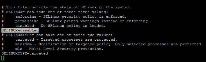
          Set SELinux to permissive by editing the "/etc/selinux/config" file, making sure the SELINUX flag is set as follows.

          SELINUX=permissive

          The server will need a reboot for the change to take effect.

          Setup

          Before we consider the packages required by the Oracle installation, it's probably worth making sure some basic package groups are installed.

          dnf groupinstall "MATE Desktop" -y
          dnf groupinstall "Development Tools" -y
          dnf groupinstall "Administration Tools" -y
          dnf groupinstall "System Tools" -y
          dnf install firefox -y

          If you have installed the suggested package groups, the majority of the necessary packages will already be installed. The following packages are listed as required, including the 32-bit version of some of the packages. Many of the packages should be installed already.

          dnf install binutils -y
          dnf install compat-libstdc++-33 -y
          dnf install compat-libstdc++-33.i686 -y
          dnf install gcc -y
          dnf install gcc-c++ -y
          dnf install glibc -y
          dnf install glibc.i686 -y
          dnf install glibc-devel -y
          dnf install glibc-devel.i686 -y
          dnf install ksh -y
          dnf install libgcc -y
          dnf install libgcc.i686 -y
          dnf install libstdc++ -y
          dnf install libstdc++.i686 -y
          dnf install libstdc++-devel -y
          dnf install libstdc++-devel.i686 -y
          dnf install libaio -y
          dnf install libaio.i686 -y
          dnf install libaio-devel -y
          dnf install libaio-devel.i686 -y
          dnf install libXext -y
          dnf install libXext.i686 -y
          dnf install libXtst -y
          dnf install libXtst.i686 -y
          dnf install libX11 -y
          dnf install libX11.i686 -y
          dnf install libXau -y
          dnf install libXau.i686 -y
          dnf install libxcb -y
          dnf install libxcb.i686 -y
          dnf install libXi -y
          dnf install libXi.i686 -y
          dnf install make -y
          dnf install sysstat -y
          dnf install unixODBC -y
          dnf install unixODBC-devel -y
          dnf install zlib-devel -y

          Create the new groups and users.

          groupadd -g 54321 oinstall
          groupadd -g 54322 dba
          groupadd -g 54323 oper
          #groupadd -g 54324 backupdba
          #groupadd -g 54325 dgdba
          #groupadd -g 54326 kmdba
          #groupadd -g 54327 asmdba
          #groupadd -g 54328 asmoper
          #groupadd -g 54329 asmadmin

          useradd -u 54321 -g oinstall -G dba,oper oracle
          passwd oracle

          We are not going to use the extra groups, but include them if you do plan on using them.
          Create the directories in which the Oracle software will be installed.

          mkdir -p /u01/app/oracle/product/12.1.0.2/db_1
          chown -R oracle:oinstall /u01
          chmod -R 775 /u01

          Putting mount points directly under root is typically a bad idea. It's done here for simplicity, but for a real installation "/" should be reserved for the OS.

          If you are using X Emulation, login as root and issue the following command.

          xhost +

          Edit the "/etc/redhat-release" file replacing the current release information "Fedora release 25" with the following.

          redhat release 7

          Login as the oracle user and add the following lines at the end of the "/home/oracle/.bash_profile" file.

          # Oracle Settings
          export TMP=/tmp
          export TMPDIR=$TMP

          export ORACLE_HOSTNAME=fedora25.localdomain
          export ORACLE_UNQNAME=cdb1
          export ORACLE_BASE=/u01/app/oracle
          export ORACLE_HOME=$ORACLE_BASE/product/12.1.0.2/db_1
          export ORACLE_SID=cdb1

          export PATH=/usr/sbin:$PATH
          export PATH=$ORACLE_HOME/bin:$PATH

          export LD_LIBRARY_PATH=$ORACLE_HOME/lib:/lib:/usr/lib
          export CLASSPATH=$ORACLE_HOME/jlib:$ORACLE_HOME/rdbms/jlib

          Installation

          Log into the oracle user. If you are using X emulation then set the DISPLAY environmental variable.

          DISPLAY=:0.0; export DISPLAY

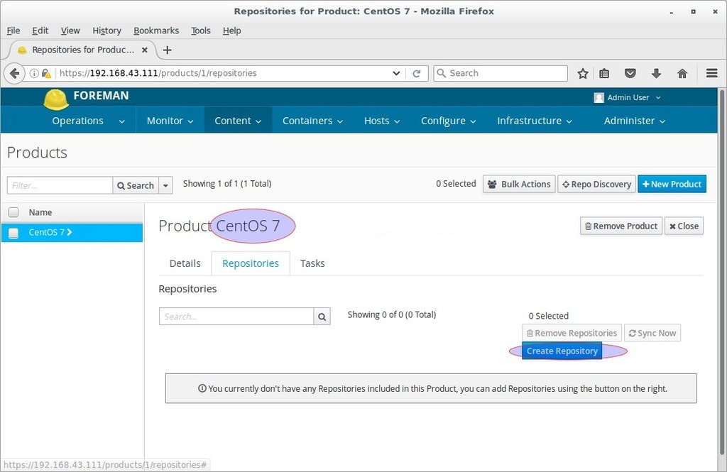
          Start the Oracle Universal Installer (OUI) by executing the following command in the database directory.

          ./runInstaller

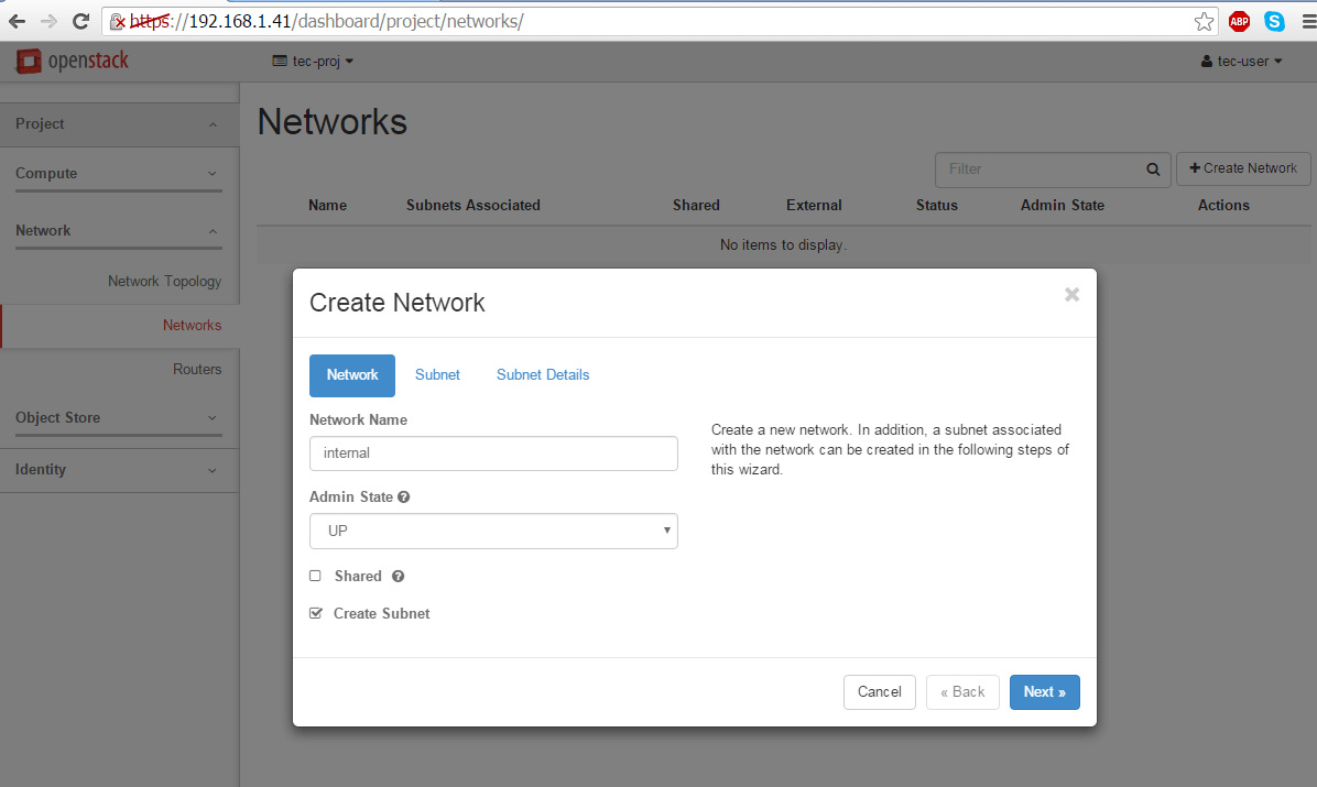
          Proceed with the installation of your choice. Ignore any warnings about the system configuration.

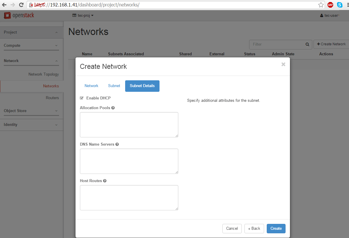
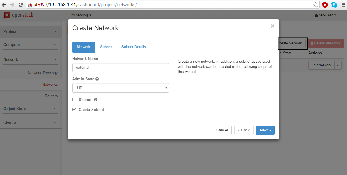
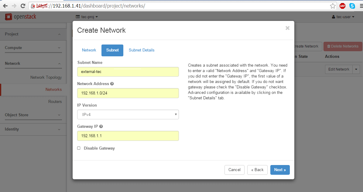
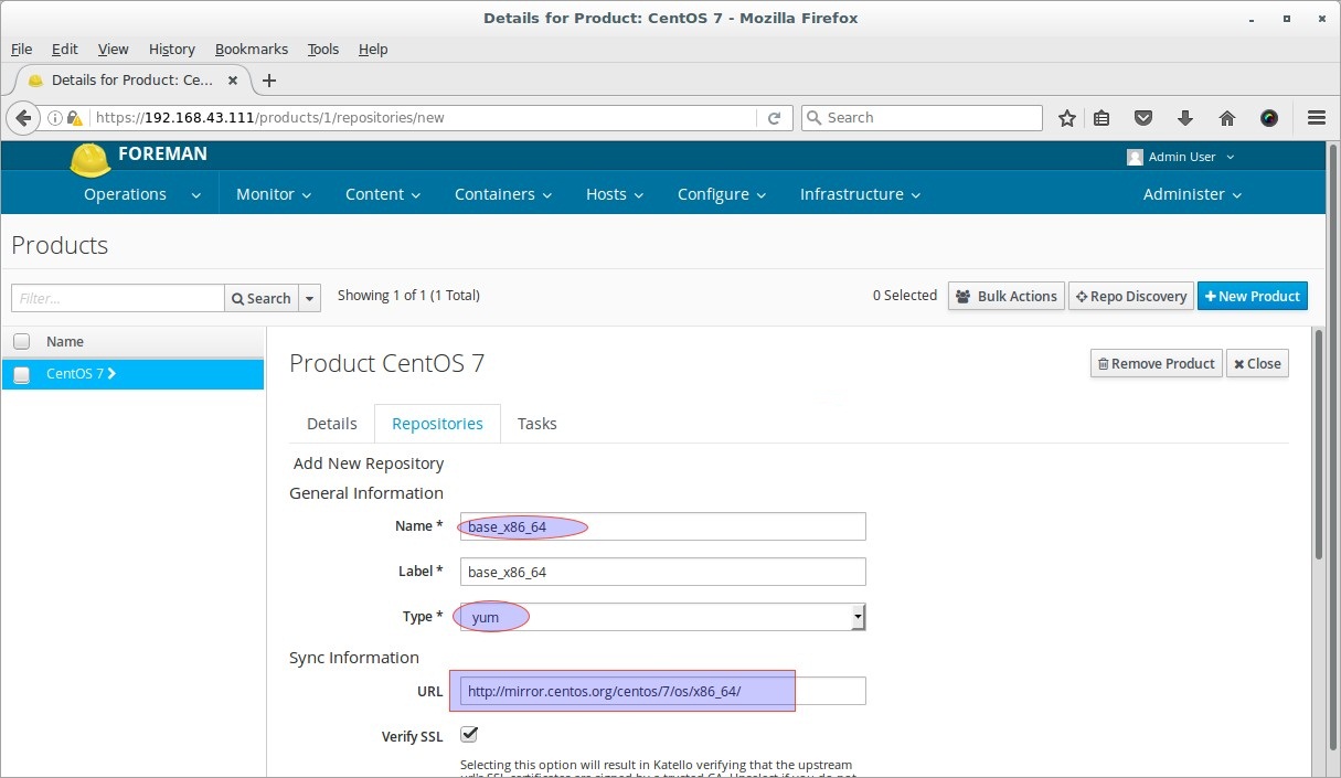
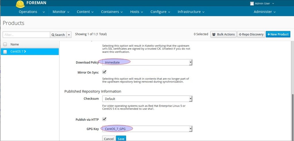
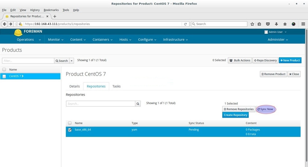
          You can see the following screenshots for reference and type of installation we performed.

          Configure Security Updates and Click Next


          My Oracle Support Credentials error because i don't use it. Click Yes


          Select Installation Type and Click Next


          Choose the System Class and Click Next


          Choose Grid Installation Options and Click Next


          Select Install Type and Click Next


          Provide Typical Install Configuration settings and Click Next


          Provide Inventory Directory path and Click Next


          Performing Prerequisite Checks, when done click Next


          This is the Summary screen of all your configuration, if all well click Install


          Installing Product


          Execute Configuration Scripts from the fedora terminal then click Ok


          Performing Oracle Database Configuration


          Performing Database Configuration Assistant


          Database Configuration Assistant Completed. Note down the highlighted url and Click OK


          Click Finish


          Open up your favorite web browser and access the above noted url.

          Database Express 12c Login screen presented. Login with username and password you specify in above step.


          Database Express 12c Dashboard screen presented.


          Installation Problems

          If you are doing this installation in a VM on a Mac/PC with a new-ish chipset, you may encounter some issues, especially around the Perl installation. If so, check out these notes.

          During the linking phase, you may see the following error.

          Error in invoking target 'irman ioracle' of makefile '/u01/app/oracle/product/12.1.0.2/db_1/rdbms/lib/ins_rdbms.mk'

          To fix it, run the following command as the "oracle" user, then click the "Retry" button.

          cp  $ORACLE_HOME/javavm/jdk/jdk6/lib/libjavavm12.a $ORACLE_HOME/lib/

          During the database creation as part of the installation, or after when using the DBCA, you may get the following error.

          Error while executing "/u01/app/oracle/product/12.1.0.2/db_1/rdbms/admin/dbmssml.sql". Refer to "/u01/app/oracle/cfgtoollogs/dbca/orcl/dbmssml0.log" for more details. Error in Process: /u01/app/oracle/product/12.1.0.2/db_1/perl/bin/perl

          To fix it, follow the instructions to rebuild Perl as described towards the end of this post by Laurent Leturgez. You will have to redo the database creation.

          Post Installation

          Edit the "/etc/redhat-release" file restoring the original release information.

          Fedora release 25

          Edit the "/etc/oratab" file setting the restart flag for each instance to 'Y'.

          cdb1:/u01/app/oracle/product/12.1.0.2/db_1:Y

          Conclusion

          This is for your information that oracle database is not supported and we do not recommend keeping oracle database on fedora Linux in production environment. However, consider using oracle Linux or red hat enterprise instead.

          Installing Puppet 4 on Ubuntu 16.04

          $
          0
          0

          This guide will walk you through the steps to install open source Puppet 4 in a master-agent setup on Ubuntu 16.04. Through the Puppet master server which runs the Puppet Server software you can control all other servers, called Puppet agent nodes.


          Prerequisites

          To follow the steps mentioned in this article, you will need three Ubuntu 16.04 servers installed on either (physical or virtual) machines, each with a non-root user with sudo privileges.

          Puppet Master

          One Ubuntu 16.04 server will be the Puppet master. The Puppet master will run Puppet Server, which is resource intensive and requires at least:
          • 4 GB of memory
          • 2 CPU cores
          If you want manage larger infrastructures, the Puppet master will definitely require more resources.

          Puppet Agents

          The remaining two servers will be Puppet agent nodes, managed by the Puppet master. We'll call them dbserver1 and webserver1.

          When these three Ubuntu 16.04 servers are in place, you're ready to begin.

          Configuring /etc/hosts

          Puppet master servers and the nodes they manage need to be able to communicate with each other. In most situations, this will be accomplished using DNS, either configured on an externally hosted service or on self-hosted DNS servers maintained as part of the infrastructure.

          DNS is its own domain of expertise, however, even on hosted services, so in order to focus on the fundamentals of Puppet itself and eliminate potential complexity in troubleshooting while you're learning, in this article we'll use the /etc/hosts file instead.

          On all three Ubuntu machines, edit the /etc/hosts file. At the end of the file, specify the Puppet master server as follows, substituting the IP address for your Puppet master:

          sudo nano /etc/hosts
          puppet_ip_address    puppet-master

          Save and close.

          Installing Puppet Server

          Puppet Server is the software that pushes configuration from the Puppet master to the other servers. It runs only on the Puppet master; the other hosts will run the Puppet Agent.

          We'll enable the official Puppet Labs collection repository with these commands:

          curl -O https://apt.puppetlabs.com/puppetlabs-release-pc1-xenial.deb
          sudo dpkg -i puppetlabs-release-pc1-xenial.deb
          sudo apt-get update

          When apt-get update is complete, ensuring that we'll be pulling from the Puppet Labs repository, we'll install the puppetserver package:

          sudo apt-get install puppetserver

          Press Y to proceed. Once installation is complete, and before we start the server, we'll take a moment to configure the memory.

          Configure memory allocation

          By default, Puppet Server is configured to use 2 GB of RAM. You can customize this setting based on how much free memory the master server has and how many agent nodes it will manage.

          To customize it, open /etc/default/puppetserver:

          sudo nano /etc/default/puppetserver

          Then find the JAVA_ARGS line, and use the -Xms and -Xmx parameters to set the memory allocation. We'll increase ours to 3 gigabytes:

          /etc/default/puppetserver
          JAVA_ARGS="-Xms3g -Xmx3g -XX:MaxPermSize=256m"

          Save and exit.

          Open the firewall

          When you start Puppet Server, it will use port 8140 to communicate, so make sure it's open by executing the following command

          sudo ufw allow 8140

          Next, we'll start Puppet server.

          Start Puppet server

          You can execute systemctl command to start Puppet server:

          sudo systemctl start puppetserver

          This will take some time to complete.

          Once you are returned to command prompt, verify puppetserver status

          sudo systemctl status puppetserver

          You should see a line that says "active (running)" and the last line should look something like:

          Output
          Dec 07 16:27:33 puppet systemd[1]: Started puppetserver Service.

          Now that you've ensured the server is running, let's configure it to start at boot:

          sudo systemctl enable puppetserver

          With the server running, now you're ready to set up Puppet Agent on our two agent machines, dbserver1 and webserver1.

          Installing the Puppet Agent

          The Puppet agent software must be installed on any server that the Puppet master will manage. In most cases, this will include every server in your infrastructure.

          Enable the official Puppet Labs repository

          First you'll enable the official Puppet Labs collection repository with these commands:

          dbserver1$ wget https://apt.puppetlabs.com/puppetlabs-release-pc1-xenial.deb
          dbserver1$ sudo dpkg -i puppetlabs-release-pc1-xenial.deb
          dbserver1$ sudo apt-get update

          Install the Puppet agent package

          Then, you'll install the puppet-agent package:

          dbserver1$ sudo apt-get install puppet-agent

          Start the agent and enable it to start on boot:

          dbserver1$ sudo systemctl start puppet
          dbserver1$ sudo systemctl enable puppet

          Now, repeat these steps on webserver1:

          webserver1$ wget https://apt.puppetlabs.com/puppetlabs-release-pc1-xenial.deb
          webserver1$ sudo dpkg -i puppetlabs-release-pc1-xenial.deb
          webserver1$ sudo apt-get update
          webserver1$ sudo apt-get install puppet-agent
          webserver1$ sudo systemctl enable puppet
          webserver1$ sudo systemctl start puppet

          Now that both agent nodes are running the Puppet agent software, we will sign the certificates on the Puppet master.

          Signing Certificates on Puppet Master

          The first time Puppet runs on an agent node, it sends a certificate signing request to the Puppet master. Before Puppet Server will be able to communicate with and control the agent node, it must sign that particular agent node's certificate.

          List current certificate requests

          To list all unsigned certificate requests, run the following command on the Puppet master:

          sudo /opt/puppetlabs/bin/puppet cert list

          There should be one request for each host you set up, that looks something like the following:

          Output:
            "dbserver1.localdomain" (SHA256) 46:19:79:3F:70:19:0A:FB:DA:3D:C8:74:47:EF:C8:B0:05:8A:06:50:2B:40:B3:B9:26:35:F6:96:17:85:5E:7C
            "webserver1.localdomain" (SHA256) 9D:49:DE:46:1C:0F:40:19:9B:55:FC:97:69:E9:2B:C4:93:D8:A6:3C:B8:AB:CB:DD:E6:F5:A0:9C:37:C8:66:A0

          A + in front of a certificate indicates it has been signed. The absence of a plus sign indicates our new certificate has not been signed yet.

          Sign requests

          To sign a single certificate request, use the puppet cert sign command, with the hostname of the certificate as it is displayed in the certificate request.

          For example, to sign dbserver1's certificate, you would use the following command:

          sudo /opt/puppetlabs/bin/puppet cert sign db1.localdomain

          Output similar to the example below indicates that the certificate request has been signed:

          Output:
          Notice: Signed certificate request for dbserver1.localdomain
          Notice: Removing file Puppet::SSL::CertificateRequest dbserver1.localdomain at '/etc/puppetlabs/puppet/ssl/ca/requests/dbserver1.localdomain.pem'

          The Puppet master can now communicate and control the node that the signed certificate belongs to. You can also sign all current requests at once.

          We'll use the --all option to sign the remaining certificate:

          sudo /opt/puppetlabs/bin/puppet cert sign --all

          Now that all of the certificates are signed, Puppet can manage the infrastructure.

          Verifying the Installation

          Puppet uses a domain-specific language to describe system configurations, and these descriptions are saved to files called "manifests", which have a .pp file extension. We'll create a brief directive to verify that the Puppet Server can manage the Agents as expected.

          We'll begin by creating the default manifest, site.pp, in the default location:

          sudo nano /etc/puppetlabs/code/environments/production/manifests/site.pp

          We'll use Puppet's domain-specific language to create a file called it_works.txt on agent nodes located in the tmp directory which contains the public IP address of the agent server and sets the permissions to-rw-r--r--:

          site.pp example
          file {'/tmp/it_works.txt':                        # resource type file and filename
            ensure  => present,                             # make sure it exists
            mode    => '0644',                              # file permissions
            content => "It works on ${ipaddress_eth0}!\n",  # Print the eth0 IP fact
          }

          By default Puppet Server runs the commands in its manifests by default every 30 minutes. If the file is removed, the ensure directive will cause it to be recreated. The mode directive will set the file permissions, and the content directive add content to the directive.

          We can also test the manifest on a single node using puppet agent --test. Note that --test is not a flag for a dry run; if it's successful, it will change the agent's configuration.

          Rather than waiting for the Puppet master to apply the changes, we'll apply the manifest now on db1:

          sudo /opt/puppetlabs/bin/puppet agent --test

          The output should look something like:

          Output
          Info: Using configured environment 'production'
          Info: Retrieving pluginfacts
          Info: Retrieving plugin
          Info: Loading facts
          Info: Caching catalog for db1.localdomain
          Info: Applying configuration version '1481131595'
          Notice: /Stage[main]/Main/File[/tmp/it_works.txt]/ensure: defined content as '{md5}acfb1c7d032ed53c7638e9ed5e8173b0'
          Notice: Applied catalog in 0.03 seconds

          When it's done, we'll check the file contents:

          cat /tmp/it_works.txt

          Output
          It works on 203.0.113.0!

          Repeat this for webserver1 or, if you prefer, check back in half an hour or so to verify that the Puppet master is running automatically.


          Note: You can check the log file on the Puppet master to see when Puppet last compiled the catalog for an agent, which indicates that any changes required should have been applied.

          tail /var/log/puppetlabs/puppetserver/puppetserver.log

          Output excerpt

          2016-12-07 17:35:00,913 INFO  [qtp273795958-70] [puppetserver] Puppet Caching node for webserver1.localdomain
          2016-12-07 17:35:02,804 INFO  [qtp273795958-68] [puppetserver] Puppet Caching node for webserver1.localdomain
          2016-12-07 17:35:02,965 INFO  [qtp273795958-68] [puppetserver] Puppet Compiled catalog for webserver1.localdomain in environment production in 0.13 seconds

          We've successfully installed Puppet in Master/Agent mode.


          Viewing all 880 articles
          Browse latest View live


          <script src="https://jsc.adskeeper.com/r/s/rssing.com.1596347.js" async> </script>