Quantcast
Channel: Tech Support
Viewing all 880 articles
Browse latest View live

How to Create New Active Directory users with a PowerShell script

$
0
0

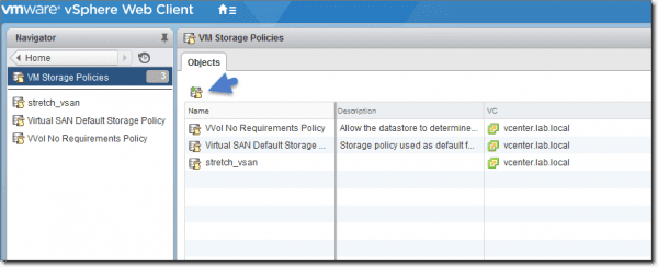
The PowerShell script discussed here allows you to create new Active Directory (AD) users, one of the most common tasks that IT admins tend to automate when it comes to employee provisioning. The reason is that this function meets all of the criteria necessary for automation. It’s a task that requires a lot of different, error-prone steps, such as ensuring user accounts meet a particular standard, creating a home folder in a certain way, creating a mailbox, and so on.


In addition, it’s a task that admins are going to repeat many times, since an organization continually hires new employees. I thought this was a great task to demonstrate typical steps that you might take when embarking on a new script.

To get started, I’m going to assume a few prerequisites. First, I’m going to presume you have at least PowerShell v4 and also have the Active Directory module installed. The module comes as part of the Remote Server Administration Tools pack. I’m also going to assume that the machine you’ll be working is a part of a domain, that you have the required permission to create an Active Directory user account, and that the user’s home folder resides on a file server somewhere.

Because each organization’s process is going to be a little different, I’m also going to keep this as generic as possible by first demonstrating how to create an Active Directory user account based on a company standard and create their home folder somewhere. This is probably the minimum that you’ll need to do. 

However, once you get the basics of script building, you’ll see just how easy it is to script other things (adding something to an HR application, creating an Exchange mailbox, etc.).


Planning employee provisioning

Let’s first break down each component of the goal I want to accomplish and how I intend to make it happen. By the end of script execution, I want to end up with a single AD user account and a separate folder created on a file server with appropriate permissions. To do this, I’ll need to define what exactly each of these two tasks looks like.

For example, when creating my AD user account, here are a few questions to ask yourself.
  1. In what organizational unit should it go?
  2. In what (if any) groups should it go?
    1. Is there a standard user group in which all user accounts go?
    2. Are there different groups in which a user account might go, depending on their department?
  3. What attributes need to be set at creation time?
  4. What should the username be? Does it have to follow some company standard?
When creating the home folder, these are some questions you might ask yourself.
  1. Where should the folder be created?
  2. What should the name of the folder be?
  3. What kind of permissions should the folder have?
Breaking down your goals by asking lots of questions beforehand allows you to have a picture of what the script might do before you write a single line of code.

Now that we have some rough intentions outlined, let’s answer each question before coding. Don’t worry. '

We’ll get to the code in a minute.
  1. In what organizational unit should it go? – Corporate Users
  2. In what (if any) groups should it go?
    1. Is there a standard user group in which all user accounts go? XYZCompany
    2. Are there different groups in which a user account might go, depending on their department? Match group name with the department.
  3. What attributes need to be set at creation time?
    1. First Name
    2. Last Name
    3. Title
    4. Department
    5. Initials
    6. Change Password at Logon
  4. What should the username be? Does it have to follow some company standard? It should be first initial, last name. If that username is already taken, it should be first initial, middle initial, and last name. If that’s taken, error out.
  5. Where should the folder be created? \\MEMBERSRV1\Users
  6. What should the name of the folder be? AD username
Now that we have each of our questions answered, let’s get down to the code.


Creating new AD users with PowerShell

We’ll first create the script and call it New-Employee.ps1. Because a lot of information will change for each employee, we need to create some parameters and dynamically pass them to the script whenever it is run. I’ll create the following variables as parameters:
  • First Name
  • Last Name
  • Middle Initial
  • Location (for the OU)
  • Department
  • Title
  • Default Group
  • Default Password
  • Base Home Folder Path
These will be represented as script parameters.

param (
[Parameter(Mandatory,ValueFromPipelineByPropertyname)]
    [ValidateNotNullOrEmpty()]
     [string]$FirstName,
     [Parameter(Mandatory,ValueFromPipelineByPropertyname)]
     [ValidateNotNullOrEmpty()]
     [string]$LastName,
     [Parameter(Mandatory,ValueFromPipelineByPropertyname)]
     [ValidateNotNullOrEmpty()]
     [string]$MiddleInitial,
[Parameter(Mandatory,ValueFromPipelineByPropertyname)]
[ValidateNotNullOrEmpty()]
 [string]$Department,
   
    [Parameter(Mandatory,ValueFromPipelineByPropertyname)]
    [ValidateNotNullOrEmpty()]
    [string]$Title,
     [Parameter(ValueFromPipelineByPropertyname)]
     [ValidateNotNullOrEmpty()]
     [string]$Location = 'OU=Corporate Users',
   
     [Parameter()]
     [ValidateNotNullOrEmpty()]
     [string]$DefaultGroup = 'XYZCompany',
     [Parameter()]
     [ValidateNotNullOrEmpty()]
     [string]$DefaultPassword = 'p@$$w0rd12345', ## Don't do this...really
     [Parameter()]
     [ValidateScript({ Test-Path -Path $_ })]
     [string]$BaseHomeFolderPath = '\\MEMBERSRV1\Users'
)
Next, I'll need to figure out what the username will be based on our defined company standard and verify the home folder doesn't exist yet.
## Find the distinguished name of the domain the current computer is a part of.
$DomainDn = (Get-AdDomain).DistinguishedName
## Define the 'standard' username (first initial and last name)
$Username = "$($FirstName.SubString(0, 1))$LastName"
#region Check if an existing user already has the first initial/last name username taken
Write-Verbose -Message "Checking if [$($Username)] is available"
if (Get-ADUser -Filter "Name -eq '$Username'")
{
    Write-Warning -Message "The username [$($Username)] is not available. Checking alternate..."
    ## If so, check to see if the first initial/middle initial/last name is taken.
    $Username = "$($FirstName.SubString(0, 1))$MiddleInitial$LastName"
    if (Get-ADUser -Filter "Name -eq '$Username'")
    {
throw "No acceptable username schema could be created"
    }
    else
    {
Write-Verbose -Message "The alternate username [$($Username)] is available."
    }
}
else
{
    Write-Verbose -Message "The username [$($Username)] is available"
}
#endregion
This part is nice because it will automatically figure out the username to use.

Script output
Script output

Next, we’ll ensure the OU and group that we’ll be using exist.

#region Ensure the OU the user's going into exists
$ouDN = "$Location,$DomainDn"
if (-not (Get-ADOrganizationalUnit -Filter "DistinguishedName -eq '$ouDN'"))
{
    throw "The user OU [$($ouDN)] does not exist. Can't add a user there"   
}
#endregion
I'll also verify the groups exists.
#region Ensure the group the user's going into exists
if (-not (Get-ADGroup -Filter "Name -eq '$DefaultGroup'"))
{
    throw "The group [$($DefaultGroup)] does not exist. Can't add the user into this group."   
}
if (-not (Get-ADGroup -Filter "Name -eq '$Department'"))
{
    throw "The group [$($Department)] does not exist. Can't add the user to this group."   
}
#endregion
And for the end of the validation phase, ensure the home folder doesn't already exist.
#region Ensure the home folder to create doesn't already exist
$homeFolderPath = "$BaseHomeFolderPath\$UserName"
if (Test-Path -Path $homeFolderPath) {
    throw "The home folder path [$homeFolderPath] already exists."
}
#endregion
We can now create the user account per company standards, add it to the group, and create the home folder.

#region Create the new user
$NewUserParams = @{
    'UserPrincipalName' = $Username
    'Name' = $Username
    'GivenName' = $FirstName
    'Surname' = $LastName
    'Title' = $Title
            'Department' = $Department
    'SamAccountName' = $Username
    'AccountPassword' = (ConvertTo-SecureString $DefaultPassword -AsPlainText -Force)
    'Enabled' = $true
    'Initials' = $MiddleInitial
    'Path' = "$Location,$DomainDn"
    'ChangePasswordAtLogon' = $true
}
Write-Verbose -Message "Creating the new user account [$($Username)] in OU [$($ouDN)]"
New-AdUser @NewUserParams
#endregion
#region Add user to groups
Write-Verbose -Message "Adding the user account [$($Username)] to the group [$($DefaultGroup)]"
Add-ADGroupMember -Members $Username -Identity $DefaultGroup
Write-Verbose -Message "Adding the user account [$($Username)] to the group [$($Department)]"
Add-ADGroupMember -Members $Username -Identity $Department
#endregion
#region Create the home folder and set permissions
Write-Verbose -message "Creating the home folder [$homeFolderPath]..."
$null = mkdir $homeFolderPath


Notice throughout this sample script that I was breaking things down into regions. Using regions is an excellent way to separate out high level tasks in a large script.

Now that you’ve done all the hard work and defined the rules, the rest is easy. You can now create as many users as you’d like that all follow the exact same pattern.

You might be interested in reading how to find active directory users with empty password using powershell script

How to Configure Ubuntu with SAMBA and Set Up the Domain Controller

$
0
0
 smb.conf mask permissions
You must have heard or have worked on Windows Domain Controller but its time to configure Ubuntu Linux Domain Controller. In this article we will show you how to setup and configure Ubuntu Linux as a Domain Controller.


Download and install SAMBA

First, obtain the latest sources in Ubuntu with these commands:

$ sudo apt-get update
$ sudo apt-get upgrade

Next, you’ll need to install several libraries and packages. However, they can all be installed with one line of code:

$ sudo apt-get install attr build-essential libacl1-dev libldap2-dev libattr1-dev libgnutls-dev libblkid-dev libpopt-dev libreadline-dev libpam0g-dev libbsd-dev libcups2-dev python-dev python-dnspython gdb pkg-config dnsutils attr krb5-user docbook-xsl acl ntp
Install SAMBA prerequisite packages 
nstall SAMBA prerequisite packages

During package installation, Kerberos will display a few pink screens and ask to configure Kerberos Authentication and define the Default Kerberos version 5 realm and the Server Name and Administrative server. Use upper-case characters, as Kerberos will have fewer problems:

Realm: TESTDOMAIN.COMServer Name: DC1.TESTDOMAIN.COM
Administrative server for Kerberos realm: DC1.TESTDOMAIN.COM
Kerberos servers for your realm 
Kerberos servers for your realm

DNS is important and required to set up our domain controller with SAMBA, so ensure that the default Ethernet interface has a static IP address assigned. To assign a static IP address, edit the file /etc/network/interfaces with vi or nano. You can use the following command to edit the file:

$ sudo vi /etc/network/interfaces
Your interfaces file should look similar to the following:

Internface configuration
Interface configuration

Notice that during the installation of our domain controller, two dns-nameservers are listed in our interfaces file (192.168.1.7 and 192.168.1.1). Once we have the domain controller running, we’ll remove the secondary upstream DNS server, as SAMBA could have problems identifying its own DNS services. Also, provide the domain name when defining the dns-search variable.

Now provide /etc/hostname with your hostname (DC1). The following screenshot demonstrates how the file will look after editing, commenting, and setting the hostname. After editing the hostname configuration file, it should return the correct name when issuing the command $ hostname.

Configure hostname and display output

Kerberos requires that the NTP (or Network Time Protocol) is accurate and synced with time servers. In this case, we’ll synchronize NTP with ntp.pool.org servers. First, stop the ntp service, set the date/time with the ntpdate command, and then start the ntp service again with the following commands:

$ sudo service ntp stop$ sudo ntpdate -B pool.ntp.org$ sudo service ntp start

The output will look similar to the following screenshot:

Synchronize ntp service with pool.ntp.org

The acl and attr packages were installed earlier, and now we need to add some additional options to /etc/fstab to extend the attributes of our ext4 file system partition located at the root /. According to Wikipedia:

“The fstab file typically lists all available disk partitions and other types of file systems and data sources that are not necessarily disk-based, and indicates how they are to be initialized or otherwise integrated into the larger file system structure.”

Below are two screenshots. The first is the original file, and the second is the file after editing. As always, it’s best to save a copy of the original file before editing. We’ll include the following options for our ext4 / partition, separated by commas:

user_xattr
 acl
 barrier=1


Original fstab file:

fstab original configuration

Here’s how the fstab file looks after editing:

fstab edited configuration 
fstab edited configuration

Because we’ve edited the way our file system initializes system partitions, we’ll restart the virtual machine to complete the options integration. This is quickly accomplished with the command:

$ sudo shutdown -r now

Configure SAMBA server as domain controller

At this point, we’re ready to configure SAMBA as a domain controller. Because we added the SAMBA file server component during the original Ubuntu operating system install, we can now run our SAMBA configuration utility SAMBA-tool. If you missed installing the SAMBA file utility during your initial system setup, get the Software selection tool again issuing the command:

$ sudo tasksel

If you do use tasksel, select SAMBA file server. Press enter.

When SAMBA is installed, we want to first remove the default smb.conf file located at /etc/samba/smb.conf. When we run SAMBA-tool, the smb.conf file will regenerate. Do this by entering the command:

$ sudo rm /etc/samba/smb.conf

Now we issue the following command to set up SAMBA with a 2008 R2 Forest Functional level:

$ sudo samba-tool domain provision --function-level=2008_R2 --interactive
The first request will be for us to provide the realm. I’ll enter my realm, TESTDOMAIN.COM (which is the FQDN for our domain), and press enter:

Realm: TESTDOMAIN.COM
Now enter the netbios name for our domain name [TESTDOMAIN]. This is our default, so we can just press enter.

Domain [TESTDOMAIN]:
Our Server Role will be a domain controller [dc]. Again, this is the default. We can simply hit enter.

Server Role (dc, member, standalone) [dc]:
Press enter again to confirm that we want the default DNS backend to use SAMBA_INTERNAL, which will add DNS entries for computers when they are joined to the domain.

DNS backend (SAMBA_INTERNAL, BIND9_FLATFILE, BIND9_DLZ, NONE) [SAMBA_INTERNAL]:
The DNS forwarder IP address is the address used when a DNS entry cannot be found on our own DNS server. I like to use my own default gateway, 192.168.1.1, for the forwarder, but you can use Google’s public DNS server 8.8.8.8.


DNS forwarder IP address (write ‘none’ to disable forwarding) [192.168.1.7]: 192.168.1.1

We’ll now be prompted to enter the Administrator (Domain admin) password for our domain. Use a long and complex password; if this part fails due to a weak password, it’ll be a difficult problem to rectify.

Administrator password:
 Retype password:
 SAMBA-tool configuration


If everything is correct, the SAMBA-tool will build the structure and directories for your domain. The output will look similar to the following:

SAMBA-tool domain build output

Modifying the permissions of the default netlogon and sysvol share directories is the last configuration change to make before we can start adding computers to our domain. To do this, edit the newly-generated /etc/samba/smb.conf file to include 0700 and 0644 permissions for both directories.

Add the following lines under the [netlogon] and [sysvol] groups:

create mask = 0700
directory mask = 0644


Your edited file will look similar to the following screenshot:

smb.conf mask permissions

After completing the SAMBA installation, go back and edit the /etc/network/interfaces file to remove your second upstream server (192.168.1.1) from the dns-nameservers group. Restart your new domain controller one final time, and the server will be ready to accept computers into the domain. Use the following command:

$ sudo reboot

Join a Windows workstation to the new domain

After the domain controller has completed its reboot, Windows workstations can join the domain. For Windows 7, you’ll need Windows 7 Pro or Ultimate. For Windows 8 and Windows 10, you’ll want at least the Professional version.

In Windows 10, right-click on the start menu, and click System.

Windows 10 system settings

Under Computer settings, click Change Settings and then the Change button. Enter the name of your domain (testdomain.com), and click OK.

System properties and join domain 


System properties and join domain

If you receive the following error, it means the workstation you’re trying to join either isn’t able to ping the IP address of the domain controller and/or you need to explicitly set the DNS entry in TCP/IP V4 to include your domain controller’s IP address:

An Active Directory Domain Controller (AD DC) for the domain “testdomain.com” could not be contacted.

Once your Windows workstation can contact the domain controller, you’ll be greeted with a prompt to authenticate. Type in the user name (Administrator) and the password you provided during the SAMBA-tools setup. Click OK, and your workstation will now be a member of the domain.

Welcome to the domain

You’ll be prompted to restart the workstation. After the reboot, log on to the domain with your username (Administrator) and password. You can now use Active Directory Users and Computers (ADUC) as well as other administrative tools to configure a domain and set up user accounts, GPO’s, and home directories.

How to Disable Updates in Windows 10 1607 using Group Policy

$
0
0
In Windows 10 1607 (Anniversary Update), the Windows Update setting no longer offers a drop down menu to disable updates. However, you can still turn off Automatic Updates with Group Policy. New is a feature that allows you to configure Active hours and Restart options.


In Windows 10 1511 (November Update), you could set Windows Update to “Automatic” or to “Notify to schedule restart” under the Advanced options of the Windows Update settings.

 
Advanced options in Windows 10 1511

Although I could not find an official statement, it appears that these options have disappeared in Windows 10 1607. The Advanced options no longer offer a drop down menu for changing the Automatic Updates setting:


Advanced options in Windows 10 1607

The reason probably is the new Active hours feature (see below). However, the missing drop down menu can cause confusion when you configure Windows Update via Group Policy.


Disable Automatic Updates

The Group Policy Configure Automatic Updates (Computer Configuration > Policies > Administrative Templates > Windows Components > Windows Update) has all the options of previous Windows versions: Notify for download and notify for install, Auto download and notify for install, and Auto download and schedule the install. The option, Never check for updates (not recommended), of previous Windows versions, can be configured by disabling the policy.

 
Configure Automatic Updates policy

If you configured one of the policies in Windows 10 1511, the Windows Update settings would inform the end user that “some settings are managed by your organization.”


“Some settings are managed by your organization” in Windows 10 1511

In the Advanced options of the Windows Update settings, the user could then see what settings the administrator has configured via Group Policy, but would then be unable to change the configuration.


End user cant change Windows Update settings in Windows 10 1511

If you apply any of the policies to Windows 10 1607, the Windows Updates settings don’t show any information about the configuration. However, based on my tests, the Anniversary Update still supports these policies.

When I gave my test machine access to the internet, without enabling any update policy , Windows Update always began by downloading new updates after a couple of minutes. The Windows Update settings usually displays the updates that are currently downloaded.

However, when I disabled the Automatic Updates via Group Policy, no downloads were shown. With the help of the networking monitoring tool, I could see that Windows downloaded a couple of megabytes from Windows Update, but then stopped. Even after several hours, no new updates appeared in the Update History.

I also tried the setting Notify for download and notify for install in Windows 10 1607, and it worked as expected. When new updates are available, the user will receive a systray message.


Systray message “You need some updates”

And if the user missed the message, the Action Center keeps a record.


“You need some updates” in the Action Center

A click on the message, will bring the user to the Windows Update settings where the updates can then be downloaded.


“Updates are available” in Windows Update settings

I didn’t try the other Group Policy settings for Automatic Updates, but my guess is that they still work, even though the Update settings no longer show how admins have configured the computer.


Active hours

Although it is no longer possible to configure the behavior of Automatic Updates within the Windows 10 settings of the Anniversary Update, two new links are now visible: Change active hours and Restart options.


Change active hours and Restart options Windows 10 1607

The Active hours option allows you to configure for the times when Windows won’t restart because an update is due to be installed.


Active hours

You can configure Active hours through Group Policy. Note that you can only see the new policy after you update the ADMX templates with the latest version for Windows 10 in the PolicyDefinitions folder on your Windows Server or in the Central Store.


Group Policy “Turn off auto restart for updates during active hours”

If you apply this policy to a Windows 10 1607 machine, the corresponding configuration in the local settings app won’t change. However, according to my tests, restarts will then be scheduled corresponding to the Group Policy, and the Active hours configuration in the Windows 10 settings will be ignored.

Restart options

The Restart options can only be configured when a restart is scheduled. In this case, the user will receive a corresponding systray message and the restart time can then be rescheduled.


Restart options and Restart required message

Once a restart is scheduled, the Active hours link in the Windows settings will then disappear.


Active hours link disappears when a restart is scheduled

Conclusion

The fact that the Group Policy configuration for Automatic Updates is no longer displayed in the Windows 10 1607 settings is confusing. However, the ability to centrally and locally configure Active hours, as a way of preventing unwanted restarts, is advantageous. I also appreciate being able to configure another restart time once the updates are downloaded.

Unwanted restarts were certainly the major annoyance of Windows Update. However, if bandwidth consumption is your concern, then you might consider working with metered connections. With the help of a little PowerShell script, you can switch an Ethernet connection between metered and not metered. I will cover this option in my next post.

How to Disable Web Search on Windows 10 Start Menu using Group Policy

$
0
0
By default, when you enter a keyword in the search box of the Start menu, Windows 10 will also search the web via Bing. In my view, it makes a lot of sense to disable this feature on all the computers in your network via Group Policy.


If I remember it right, Google brought up this weird idea of integrating desktop search with web search. When Google introduced a sidebar for Windows XP that allowed you to search in files on your desktop and the web, many bloggers around the planet interpreted this as a declaration of war against Microsoft. Steve Ballmer agreed with the bloggers and the software maker introduced Desktop Search, which was later renamed to Windows Search.

Why do disable web results in Search

According to me, it doesn’t make any sense from the user’s point of view to integrate desktop search and web search. It is like if a search of the local library catalog includes the products from the grocery next door—you know, just in case you are searching for a cookbook and want to shop for the ingredients for your next recipe after your library visit.
Integrating web search in the Windows 10 Start menu might make sense from Microsoft’s point of view because it helps the software giant push Bing. However, I doubt that this feature really improves the Windows 10 user experience because it devalues Search. If I want to find an item on my computer, I don’t need to search it on all the web servers on the planet. The effect is that the search results are cluttered with irrelevant links that only help lose focus and waste space on the tiny Start menu.

I think that, instead of pushing Bing, Microsoft should ensure that local search works properly, which it often does not. For instance, if you want to launch PowerShell ISE and you type “powershell” in Search, on a freshly-insatlled Windows 10 computer, you won’t find Microsoft’s scripting tool. Instead, it displays a lot of irrelevant web links. You have to type “powershell ise” to find PowerShell ISE. If I really want to search for a PowerShell tutorial on the web, I use my web browser and the search engine of my choice.

You also have to take into account privacy. If users search for confidential information on the desktop, say a password stored in a local file, you don’t want this keyword to be sent across the web.

Another reason you might want to disable web search in Start is the News links that Windows 10 displays when you click the search box. Why would any employer want to encourage users to read the news during work time?

 
Start loads news from the web.

Thus, I recommend disabling web search in the Windows 10 Start menu. If you just want to get rid of web search on your own computer, you just have to click the search box and then click the settings symbol on the left.

I think that, instead of pushing Bing, Microsoft should ensure that local search works properly (which it often does not). For instance, if you want to launch PowerShell ISE on a freshly installed Windows 10 and you type “powershell” in Search, Windows 10 won’t find Microsoft’s scripting tool; instead, it displays a lot of irrelevant web links. You have to type “powershell ise” to find PowerShell ISE. If I really want to search for a PowerShell tutorial on the web, I use my web browser and the search engine of my choice.


PowerShell ISE can be hard to find with Start Search.

Another thing to take into account is privacy. If users search for confidential information on the desktop, say a password stored in a local file, you don’t want this keyword to be sent across the web.

Disable web search results on a local computer

Thus, I recommend disabling web search in the Windows 10 Start menu. If you just want to get rid of web search on your own computer, you merely have to click the search box and then click the settings symbol on the left.


Search settings in Windows 10

You can then configure Search to not search online or include web results.


Disable “Search online and include web results”

As you can see in the screenshots above, this setting will change the text in the search box from “Search the web and Windows” to “Search Windows.”

Turn off web search results with Group Policy

If you want to disable web search results in Start on all your computers in the network, you can enable the Group Policy Don’t search the web or display web results in Search, which you can find in Computer Configuration > Policies > Administrative Templates > Windows Components.


Don’t search the web or display web results in Search

After I ran gpupdate, I had to sign out and sign in again for the policy to take effect.

Note that this policy also disables Cortana. Microsoft’s personal assistant needs access to Bing and therefore can’t work if you disable web search. I’d say this is a welcome side effect of this policy because this AI toy is another Windows 10 feature that only distracts users from their work.

If users then open the search settings, they will be informed that Cortana and Online Search have been disabled by company policy.


Search and Cortana are disabled by company policy.

A second policy exists that allows you to disable this feature only for metered connections. Microsoft likely added this policy because Start downloads pictures from news sites when you click the search box.

By the way, don’t confuse this Windows 10 policy with the Do not allow web search policy. As far as I could see, this policy has no effect on Windows 10. It only affects older Windows versions that run the old Desktop search.

What is your view about the web search integration in Start?

How to Configure RAID 5/6 (erasure coding), deduplication, and compression - VMware VSAN

$
0
0

In this article I will show you how to configure RAID 5/6 (erasure coding), deduplication, and compression on VMware vSAN.


Erasure coding is a general term that refers to any scheme of encoding and partitioning data into fragments in a way that allows you to recover the original data even if some fragments are missing. Any such scheme is referred to as an “erasure code.”

By activating erasure coding on a VSAN cluster, you’ll be able to spread chunks of the VM’s files to several hosts within the cluster.

As of version 6.2, Virtual SAN supports two specific erasure codes:
  • RAID 5– 3 data fragments and 1 parity fragment per stripe
  • RAID 6– 4 data fragments, 1 parity, and 1 additional syndrome per stripe
Note that a Virtual SAN cluster has to consist of at least 4 to 6 hosts. Of course, it may be (much) larger than that. A VSAN cluster is limited by the maximum vSphere cluster size, which is 64 hosts.

The Requirements: The hardware and HCL for VSAN requirements are the same as for other configuration types of VSAN: a minimum of 4 hosts for RAID 5 and a minimum of 6 hosts for RAID 6.
Make sure that each host has at least one SSD available for the cache tier and one or several SSDs available for the capacity tier. Note that erasure coding is only available for the VSAN All-Flash version.

The Configuration Steps: Basically, you’ll need hardware that is capable of running VSAN and a VSAN license. Then only a few configuration steps, including network configuration, are necessary.

I assume that you know how to create a Datacenter object and cluster object, how to add hosts to vCenter, and how to move the hosts that will be used for VMware VSAN into the VSAN cluster. Once you’ve completed these steps, select the VSAN cluster > Manage tab > Virtual SAN > Edit. The VSAN configuration assistant will launch.

You have the option of controlling how the local disks are claimed for VSAN. If this is done automatically (assuming that all disks are blank and have a similar vendor mark/capacity). Or you can do it manually and control which disks will be part of the cache tier and which will be part of the capacity tier.

 
VMware VSAN erasure coding configuration

Then we have the networking requirements. Each host has to have one VMkernel adapter activated for VSAN traffic.

VMware VSAN erasure coding configuration – Networking requirements

Here you can see the disk claim page. This page is same for all versions of VSAN and allows you to tag/un-tag disks as Flash or as HDD. This is for cases in which VSAN does not recognize the hardware automatically.

 
VMware VSAN erasure coding configuration – Disk claim

Then we have the overview page. As you can see, I have already claimed my disks for the previous use cases with VSAN, so I only added two new hosts to my cluster in order to show the erasure coding configuration. On the review screen, you can see that 160 Gb were already claimed.

 
Overview of VMware VSAN erasure coding configuration

Click the Finish button and wait few minutes until the VSAN datastore is created and the system shows you that VSAN is on.

As you can see, so far we have just created a VSAN cluster. We now need to create a VM storage policy.
An overview of both policies is given below. Remember that failure to tolerate (FTT) refers to how many failures the VSAN cluster can tolerate.

Raid 5 configuration:
  • Number of failures to tolerate (FTT) = 1
  • Failure tolerance method = capacity
  • Compared to RAID 1, VSAN uses only x1.33 rather than x2 capacity
  • Requires a minimum of 4 hosts in the VSAN-enabled cluster
Raid 6 configuration:
  • Number of failures to tolerate (FTT) = 2
  • Failure tolerance method = capacity
  • Compared to RAID 1, VSAN uses only x1.5 rather than x3 capacity
  • Requires a minimum of 6 hosts in the VSAN-enabled cluster
The diagram below illustrates the configurations (courtesy of VMware).


RAID 5 and RAID 6 configurations

Then we can start and create the RAID 5 and RAID 6 policies. Connect via vSphere web client and click the VM Storage Policies icon on the Home tab.

 
Configure VM storage policies

On the next page, click Create a new VM storage policy.

 
Create a new VM storage policy

Then follow the assistant.


Create a new VM storage policy – Assign a name

Now you’ll see an overview page explaining what VM storage policy is and what the rules and requirements for the storage resources are.

 
Create a New VM Storage Policy – Overview Page

We can now start adding rules. Make sure to select the VSAN from the Rules based on data services drop-down menu. Then choose Failure tolerance method to start with.

 
Create a new VM storage policy – Failure tolerance method

Next select Raid 5/6 (erasure coding) – Capacity from the drop-down menu. You’ll see an example calculation on the right telling you how much storage space the VM will consume. In our example, for a 100 Gb disk, you’ll consume 133.33 Gb of VSAN storage space.

 
Create a new VM storage policy – Add rule

Similarly, you can see that for RAID1 (if you want to test it), you will basically just have a mirror that uses 200 Gb of storage space on the VSAN datastore. 

 
Create a new VM storage policy – RAID 1 example

Let’s continue with our RAID 5 policy. Add two more rules:
  • Object space reservation = 0
  • Number of failures to tolerate = 1

 
Create a new VM storage policy – RAID 5 policy

Click Finish to validate the rule.

The same you would do for RAID 6, follow the same steps but set the number of failures to tolerate to 2.

This RAID 6 options with FTT = 2 will more likely interest people who are cautious about protecting their data because with FTT = 2, you can lose two hosts and still be “on.”

Applying the VM storage policy to a VM

It is not enough to just create a VM storage policy; we also need to apply this policy to our VMs (VMDKs). It’s important to know that you can apply or change a policy on VM(s) that are running—no need to stop them. The VM’s objects get reconfigured and rebalanced across the cluster automatically and in real time.

By default, there is a “Virtual SAN Default Storage Policy” only, which utilizes RAID 1. Once you create your own RAID 5 and RAID 6 policies, you can apply this policy to existing VMs or use this policy for VMs that you migrate to your new VSAN datastore.

After you create or migrate VMs to your VSAN datastore, go to Select your VM> Policies tab > Edit VM Storage Policies button.

 
Create a new VM storage policy – Apply to VMs

Then select the RAID 5 or RAID 6 policy from the drop-down menu > hit the Apply to All button > click OK.

Create a new VM storage policy – Apply VM storage policy

Then verify that your VM’s compliance status is Compliant. You can see that our RAID 5 VM storage policy is applied to this VM.


Create a new VM storage policy – Verify compliance

The last things to activate are deduplication and compression. The VSAN All-Flash version uses these features to reduce storage space in addition to the space savings present with RAID 5/RAID 6 compared to RAID 1.

The deduplication and compression activation are shown below:

 
Create a new VM storage policy – Deduplication and compression

Click OK to validate. The conversion of the disk format will follow. When it finishes, we can see the capacity overview. (Note it’s a nested environment with only a single VM. Thus, not much deduplication is going on here.)

Select VSAN cluster object > Monitor TAB > Virtual SAN > Capacity


VMware VSAN erasure coding configuration – Deduplication and compression

I can show you a screenshot from a near production environment here:


VMware VSAN erasure coding configuration – Deduplication and compression overview


We can also verify how the virtual disks are placed on our VSAN cluster. As you can see, the components are spread out through all 6 hosts.


VMware VSAN erasure coding configuration – Physical disk placement

With RAID 5, there will be 3 data components and a parity component; with RAID 6, there will be 4 data components and 2 parity components.

Conclusion

As you can see, VMware VSAN is a software-only solution tightly integrated into the VMware stack. It’s a kernel module, so there is no need to install any virtual appliance to create shared storage. By only using local disks and SSDs, you can create a shared VSAN datastore visible to all hosts within a VSAN cluster with just a few clicks.

VSAN scales in a linear manner, which means that by adding more hosts to the cluster, you grow not only storage but also CPU and memory, making it a truly hyper-converged infrastructure.

How to Automatically Log Off idle Users in Windows

$
0
0

If you deal with computers at reception desks, in call centers, or in lab environments where users log in and never log off, computers can get really slow because of the applications left running by idle users. In this article, we'll show you how you can force those users to automatically log out with a few settings in Group Policy.


Shared computer systems in areas such as reception desks, computer labs, and call centers can be brought to their knees very quickly if users lock the workstation and walk away when their shift ends. The next person sits down, clicks Switch User, logs in, and repeats the process all over. After enough users, there are enough random applications running in the background to slow the system to a crawl. So, how do you log off the idle sessions? Actually, it’s pretty easy with a free utility and a little Group Policy.

Non-recommended solutions

Before we get started, I’d like to address two of the ways I’ve seen suggested as a way to handle logging off idle user sessions. One solution that used to be popular is the winexit.scr screensaver included in the Windows NT Server 4.0 Resource Kit. A systems administrator can set the workstation’s screensaver to winexit.scr, and the user would be logged off when the screensaver activated.

This solution doesn’t take into account newer operating systems that include Fast User Switching. It also requires you to lengthen your screensaver activation time so you don’t accidentally log off a user who has gone on a break or lunch period. And, last but not least, getting this old utility to work correctly on newer OSs is just a pain. Do you really want to run something this old on your network if you don’t have to? Another is a Group Policy setting that a lot of people point to as a solution to this problem.

The setting is located in Computer Configuration > Policies > Administrative Templates > Windows Components > Remote Desktop Services > Remote Desktop Session Host > Session Time Limits > Set time limit for disconnected sessions.


“Set time limit for disconnected sessions” policy (for RDS sessions only)

I’ve seen this setting recommended—a LOT—as a solution for logging off idle users. You can use it for logging off idle users on Remote Desktop Services (RDS, formerly Terminal Services). This session doesn’t work for physical computers that people are using at the console.


Computer-side Group Policy settings

To set up our solution, we’ll need to create a new Group Policy Object (GPO) in the Group Policy Management Console (GPMC). For multiuser computers, I usually like to create a new sub-Organizational Unit (OU) inside the original OU that contains all the other non-multiuser computers. This lets the multiuser computers get the same Group Policy as all of the other computers without forcing the “idle logoff” on every single computer.

 
Create new GPO in the Group Policy Management Console

Next, we’ll need to right-click the new GPO and choose Edit. Once you’re in the Group Policy Management Editor, you’ll need to go to Computer Configuration > Policies > Administrative Templates > System > Group Policy > Configure user Group Policy loopback processing mode. Enable the policy and set it to Merge. This will let us apply a user-side policy to computer objects in Active Directory.

 
Configure user Group Policy loopback processing mode to Merge

Next, we’ll need to copy a small utility to the multiuser computers. Go and download idlelogoff.exe. For demo purposes in this article, I’m going to put my copy into Active Directory’s Sysvol folder. For a production environment, you’ll probably want to do this from a file share. Just make sure that domain computers have at least read-only access to both the share and the file system.

 
IdleLogoff executable in the Sysvol folder

Go back to your GPO and go to Computer Configuration > Preferences > Windows Settings > Files.Right-click Files and choose New > File. In the Source File(s) section, select the IdleLogoff.exe that we put into \\domain.local\sysvol\domain.local\files\IdleLogoff\IdleLogoff.exe. Set the Destination File value to C:\Program Files\IdleLogoff\IdleLogoff.exe.


New File Properties to copy IdleLogoff.exe to computers

User-side Group Policy settings

Next, we’ll need to set our user-side Group Policy settings. Go to User Configuration > Policies > Windows Settings > Scripts (Logon/Logoff). Double-click Logon on the right side of the window.


Logon/Logoff scripts in the Group Policy Management Editor

Click the Show Files button to open a new window where you can place the Logon script we’ll use.


Create a new batch file for a Logon script

Create a new text file named IdleLogoff.bat in the folder, with the following text:

Echo off
"c:\Program Files\IdleLogoff\IdleLogoff.exe" 1800 logoff


IdleLogoff.bat example

The IdleLogoff.exe utility takes two arguments. The first argument is the time, in seconds, before taking action. In this case, I’m using 1800, which translates to 30 minutes. The second argument is the action to take. The valid actions are logoff, lock, restart, and shutdown. We want to log off idle sessions, so I’m using logoff.

Last, we need to add the Logon script to the GPO. Click the Add button on the Logon Properties window, then click the Browse button on the Add a Script window, select the script (IdleLogoff.bat), and click Open. This will take you back to the Add a Script window where you can click OK. The Logon script will show up on the Logon Properties window; click OK.


Adding the Logon script to the Group Policy Object

Testing on the client

On a test client, I’m going to run a manual Group Policy update by running gpupdate.exe at a command prompt just to ensure the system gets the settings in the GPO. Next, I’m going to go to C:\Program Files\IdleLogoff\ and make sure that IdleLogoff.exe is copied to the computer.


IdleLogoff.exe copied to a Windows 8.1 client

Next, we can run Task Manager and see that the IdleLogoff.exe executable is running in the background in the user’s session.


IdleLogoff.exe running on Windows 7


IdleLogoff.exe running on Windows 8.1
A word of warning about Windows 8: Windows 8 includes a number of changes to make the system startup and user logon process faster. One of these changes is to delay the running of logon scripts for five minutes, by default, to make the logon process faster for the end user. Keep this in mind when deploying this solution to computers. You can change this setting in Computer Configuration > Policies > Administrative Templates > System > Group Policy > Configure Logon Script Delay.


Configure Logon Script Delay policy

You might also ask, “If I can see the process, won’t the user be able to see the process?” The short answer here is, yes. The user will be able to run the Task Manager and see this process running in his/her list of processes and can stop it from running. I’ve found that 99 percent of my users logging into a workstation with this configured never know it is there. You can do things like try to hide the process from Task Manager or even rename the file to something like “explorer.exe.”

The only problem with those solutions is that those are the same things malware can do to a system. And, you probably don’t want to implement a solution that looks a lot like malware, or you run the risk of your antivirus/antimalware kicking in and killing it. You can disable the Task Manager by going to User Configuration > Administrative Templates > System > Ctrl+Alt+Del Options > Remote Task Manager. Set the policy to Enabled and click OK.


Disable the Task Manager with the Remove Task Manager policy

Lastly, communicate this new policy to people who may be impacted by the change. Some reception desk computers may need the idle logoff time set anywhere from 45 to 90 minutes so the primary user isn’t kicked out of his/her session while on a lunch break. Other locations, such as computer labs, may need it set to something lower—maybe 15 to 20 minutes.

How to Configure VMware High Availability (HA) Cluster

$
0
0

The VMware High Availability (HA) cluster supports two or more hosts (up to 64 per cluster) to reduce the risk of unplanned downtime. In this article, first I will introduce the basic concepts of VMware HA then I will to show you its configuration steps.


What can we do to reduce the impact of a host failing without prior notice? VMware’s answer to this is High Availability (HA) technology. There are two main reasons you’ll want to implement a VMware vSphere cluster and activate HA.
  1. You want to ensure high availability of your VMs. VMware HA will restart the VMs on the remaining hosts in the cluster in case of hardware failure of one of your hosts.
  2. You want to distribute your VMs evenly across the resources of the cluster. The distributed resource scheduler (DRS) (to be discussed later) will make sure that each host runs with the same level of memory and CPU utilization. If, for any reason, the use of memory or CPU rises (or falls), DRS kicks in and vMotion moves the VMs to other hosts within your cluster in order to guarantee an equal level of utilization of resources across the cluster.
In other words, HA will protect your VMs from host hardware failure, while DRS ensures that utilization of resources across the cluster is equal. So far, so simple.

 
VMware HA moves VMs

Shared vs hyper-converged storage

VMware HA works well in traditional architectures with shared storage, but what about hyper-converged storage?

Shared storage means NAS or SAN that is populated with disks or SSDs. All hosts present in the cluster can access shared storage and run VMs from a shared data store. Such architecture has been commonplace for about 15 years and has proven reliable and efficient. However, it reaches its limits in large clusters, where the storage controller’s performance becomes the bottleneck of the cluster. So basically, after you hit that limit, you end up creating another silo where you can put some hosts together with new shared storage.

Recently, hyper-converged architectures have become popular and are available from different vendors (including VMware with VSAN), where shared storage devices are replaced with the local disks in the hosts of the cluster. These local disks are pooled together across the cluster in order to create a single virtual shared data store that is visible to all hosts.

This is a software-only solution that can leverage high-speed flash devices, optionally in combination with rotating media. It uses deduplication and compression techniques, coupled with erasure coding (Raid5/6) across the cluster, in order to save storage space. We’ll look at VMware VSAN in one of our future posts.

I remember that my first demo using VMware HA was with two servers only, while the third device was a small NAS box where we had a few VMs running. This tells us that even very small enterprises can benefit from this easy-to-use technology.

HA configuration options

VMware HA is configurable through an assistant, allowing you to specify several options. You’ll need a VMware vCenter server running in your environment; VMware ESXi alone is not enough. For SMB, you’ll be fine with the vSphere Essentials Plus package, which covers you for up to three ESXi hosts and one vCenter server.

Let’s have a look at the different options that VMware HA offers.

Host Monitoring– You would enable this to allow hosts in the cluster to exchange network heartbeats and to allow vSphere HA to take action when it detects failures. Note that host monitoring is required for the vSphere Fault Tolerance (FT) recovery process to work properly. FT is another advanced, cool technology that allows you to protect your workflows in case of hardware failure. However, compared to HA, it does that in real time, without downtime and without the need for a VM restart!


Enabling vSphere HA

Admission Control– You can enable or disable admission control for the vSphere HA cluster. If you enable it, you have to choose a policy of how it is enforced. Admission control will prevent the starting of VMs if the cluster does not have sufficient resources (memory or CPU).

Virtual Machine Options – What happens when a failure occurs? The VM options allow you to set the VM restart priority and the host isolation response.

VM Monitoring– Lets you enable VM monitoring and/or application monitoring.

Datastore Heartbeating– You have the possibility to check a secondary communication channel so vSphere can verify that a host is down. In this option, the heartbeats travel through a data store (or several). VMware datastore heartbeating provides an additional option for determining whether a host is in a failed state.

If the master agent present in a single host in the cluster cannot communicate with a slave (doesn’t receives heartbeats), but the heartbeat datastore answers, HA simply knows that the server is still working, but cannot communicate through one networking channel. In this case, we say “the host is partitioned.”

In such a case, the host is partitioned from the network or isolated; the datastore heartbeat then takes over and determines whether the host is declared dead or alive. The datastore heartbeat function helps greatly in determining the difference between a host which has failed and one that has merely been isolated from others.

In my next step, we’ll start with the network configuration of our VMware High Availability (HA) cluster, which is perhaps the toughest part of a VMware HA setup.

Let’s first have a look at the minimum requirements for setting up a VMware High Availability (HA) cluster, before we get to configuring the network.

Requirements

vSphere Essentials Plus or higher– This entitles you to run vCenter Server (providing central management and configuration) and three VMware ESXi 6.x hosts. This packaged offer can be purchased online or through software resellers.

Two hosts running vSphere 6– As stated previously, you’ll need at least two hosts in order to have an HA redundancy and stay protected in case of a server failure. The latest version of vSphere is 6.0 U2.

Two network switches with 8-10 ports. By having a dedicated storage network, you can avoid VLANs.
iSCSI storage – You’ll need iSCSI storage with two storage processors and several NICs. I’m assuming that you either have your storage array configured or you plan to follow the network configuration of your hardware supplier.

To keep things simple while configuring maximum redundancy, I assume that we’ll be using a separate network for storage and for vSphere networking (for management, vMotion, etc). This means that each of your hosts will need at least four NICs (we’ll be using two for storage), while the storage array also has four (two per storage processor).

Network configuration

The first thing to do when preparing for VMware vSphere deployment is to plan ahead in your network, not only in the network-only environment but also in the storage environment, as most storage-based solutions are Ethernet-based iSCSI or NFS.

It is a small network configuration that I will place emphasis on today. The guide will work with the smallest possible redundant storage network configuration for two hosts connected to iSCSI storage.

Whether you’re just setting up a POC (prove of concept) environment or real deployment, you should have the following:
  • A list of IP addresses you’ll be using
  • An established naming convention for your ESXi hosts
  • A base network service, such as AD, DNS, or DHCP, that is configured and running
Let’s take a look at our networking setup:

Redundant iSCSI Network Storage Configuration

On the right, we have a storage array connected to two storage switches in order to provide redundancy. We’re using two completely different storage networks for the array.

There are only two hosts in the image, but you can easily add a third and, potentially, a fourth host in order to expand your cluster. This merely depends on the requirements for properly sizing the network switches with a correct number of network ports, in order to satisfy future growth.

The VMware vSphere configuration (for storage) isn’t difficult, but one has to keep in mind that only one NIC can be configured as active in the vSwitch, otherwise you can’t bind your iSCSI initiator to the iSCSI target.

All IP addresses of Network 1, marked in blue, will use a base address of the subnet 10.10.3.x. Then, we do the same thing for Network 2, which has a base address of 10.10.4.x. In the image, this network is marked in red.

As you can see, all the ESXi port groups are following this numbering scheme to stay within the same range. In this way, it’s very easy to assign IP addresses while constantly ensuring you’re “navigating” within the right network range.

 
A completely redundant iSCSI network

If the array has less than four ports per SP, you can still assure redundancy by “cross-linking” the switches. I am aware that my guide represents a very generous storage array with four network ports per storage processor.

As we now have the networking hardware for our HA cluster in place, we can start by configuring vSphere.

Configuring VMware vSphere

First, we’ll need to add a VMkernel network port. Open the vSphere client and start the assistant: Select your host> Configuration TAB> Networking> Add Networking> Select VMkernel radio button.

As you can see in the screenshot below, I’m adding a separate virtual switch to our host. This is something that is not necessary (we can configure the iSCSI network on the existing vSphere switch), but I like to separate iSCSI from the other networks I’m using on each host, by creating a separate vSwitch – in our example, vSwitch 1.


Create a New vSphere standard switch

You can also see that I’m selecting both NICs to be added to this switch. I’ll use both of those for our redundant iSCSI configuration.

Now, you just have to follow the Add Network Wizard.


Create a new vSphere standard switch – Network label

In the next step, you have to assign an IP address. Finish the assistant and add an additional VMkernel adapter to this vSwitch by clicking the Properties link > Add > VMkernel > Put Network Label > Next > IP address and Network mask > Done.

Make sure to have always one active and one unused VMnic adapter for each iSCSI VMkernel port. This is important, because otherwise you won’t be able to bind the VMkernel port adapters to a VMnic later on.

 
Override switch failover order

Check Override switch failover order for active and unused NICs.

This concludes today’s post. We are about halfway through what’s required for a redundant iSCSI storage network.

Today we learned how to:
  • Plan a redundant iSCSI network for two or more VMware vSphere hosts.
  • Assign static IP addresses to our iSCSI array. We did not demonstrate this in detail because we don’t have a spare array in the lab, but I think you got the idea or followed your vendor’s recommendations.
  • We created a separate switch for iSCSI SAN network traffic and configured active and unused VMnic adapters on each vSwitch.
In the next step, we will create iSCSI initiators and configure a Path Selection Policy (PSP). VMware uses Storage Array Type Plug-Ins (SATPs), which run in conjunction with the VMware NMP and are responsible for array-specific operations, such as monitoring the health of each physical path, reporting physical path changes, or activating passive paths for active-passive arrays.

We have created two separate networks between each host and storage array, which gives us a backup in case we have any of the following issues:
  • A switch failure
  • Storage processor failure
  • NIC card failure in our host
We created a fully redundant network for our iSCSI SAN storage to be prepared for a failure scenario.

In the above steps, we created a separate standard vSwitch to use for our iSCSI storage traffic. The vSwitch had been configured with 2 NICs.

Now we need to accomplish four steps:
  1. Enable the iSCSI initiator
  2. Configure the iSCSI target
  3. Create a shared datastore
  4. Set up a Round Robin storage policy

Step 1: Enable the iSCSI initiator. Select your host > Configuration> Storage Adapters> Right-click in the blank area > Add Software iSCSI Adapter.

 
VMware Storage – Add software iSCSI adapter

An assistant pops up to inform you that a new software iSCSI adapter will be added to the Storage Adapters list. After the adapter has been created, select the software iSCSI adapter in the list, right-click, and select Properties in order to configure it.

(Note: The iSCSI adapter is usually created as vmhba33.)


iSCSI configuration

You will see a window open up. Select the second tab from the left: Network configuration. You’ll see both iscsi vmk adapters that you previously added to the vSwitch1.

Click Add> Select the first iSCSI adapter> OK. Repeat for the iscsi40.


Bind VMkernel adapter with the iSCSI adapter

Step 2: Configure the iSCSI target. Now that we have added our configuration, we need to point this initiator to our array. In my case, I have an array with 2 SP with a single NIC only each.

Go back to the properties of the iSCSI initiator> Dynamic discovery tab> Add> enter the IP address of the first SP. Add all IP addresses of the array. > OK> Close> Click Yes on this message: “A rescan of the host bus adapter is recommended for this configuration change.”

 
Configuring vSphere Storage – iSCSI Target configuration

With the adapter selected, you should see the target appear on the below pane, like this:

VMware Storage – The iSCSI Target

Step 3: Create a shared datastore. Go to Configuration > Storage > Add Storage > Select Disk/LUN radio button > Next > Select the target iSCSI disk > Next > Next (a partition will be created and used) > Enter a meaningful name for the datastore > Leave the “Maximum available space” radio button checked > Next> Next.

You should see a new datastore appear. For our lab test, we have named it shared_iSCSI.

 
Shared datastore created

Step 4: Set up a Round Robin storage policy. This policy will use both paths randomly and spread availability and VM storage traffic across both links (as we have two NICs on our storage network).

Select the Datastore > Properties > Manage paths


Managing paths

This brings up another window to which you’ll have to pay a bit of attention. Select the drop-down menu and choose Round Robin (VMware)> Click the Change button > Wait a second until the policy is applied > Then click the Close button.


Specifying Round Robin as default path

We should see now multiple paths to the storage:


All paths to the iSCSI SAN

From the networking view of the iSCSI initiator, we can see that both links are used and active for iSCSI traffic.

 
Both links used for iSCSI traffic

This ends part 3 of our VMware configuration through which we’re learning how to achieve redundancy from a networking and storage perspective and how to configure VMware High Availability (HA) for our VMs. In order to configure HA, it’s imperative to have some kind of shared storage.

This can be a SAN, NAS, or from the newest hyper-convergent technologies, VMware VSAN, allowing you to leverage local SSDs and disks to create a pool of shared storage. VMware VSAN do not need any separate hardware boxes as the whole cluster acts as a software RAID.

In the next and final step of this article, I will cover the HA configuration. This will allow our VMs to be restarted in case of unwanted hardware failure, such as a host that loses a CPU or motherboard or simply goes blue screen because of a faulty RAM.

After activating HA, our cluster will become fully resilient in case we have a hardware failure on one of our hosts. This can be a faulty NIC, CPU, or motherboard, or any other part of the host. Without HA, the VMs running on a failed host would just “die,” but with HA enabled, those VMs will restart automatically on another host within our cluster.

vSphere requirements

Before I discuss the final configuration steps, I want to recap what’s necessary to activate the HA successfully:
  • A minimum of two hosts in the cluster– You can have up to 64 hosts in vSphere cluster.
  • Shared Storage– Every server that is part of the HA cluster needs to have access to at least one shared storage.
  • Network– You must connect all hosts to at least one management network. The VMkernel network with the Management Networkcheckbox has to be enabled; by default, the HA needs an accessible default gateway.
  • Licensing – All hosts must have licenses for HA. HA won’t work with an ESXi free license. You need at least vSphere Essentials.
  • VMware tools – It is highly recommended that you install VMware tools on all hosts, and it is required if you want to work with the VM monitoring feature.


Creating a VMware HA cluster

You can configure the HA cluster either with the vSphere client or with the vSphere web client. The vSphere web client also can activate the VM component protection (VMCP). This feature does not appear in the vSphere client.

Note that you can configure all clustering capabilities, HA, Distributed Resources Scheduler (DRS), vMotion, and fault tolerance (FT) on the vCenter server. However, in case the vCenter server becomes unavailable, those functions continue to work. vCenter is there only to set things up and push the configuration to the hosts.

After the vCenter installation, which I’m not detailing here, you have to create a datacenter object:

Step 1: Create a Datacenter Object


The datacenter object is at the top-level object. Bellow you will have clusters, individual hosts, folders, VMs, etc.

 
Creating a datacenter object

Now, we are ready to create the cluster.

Step 2: Create a Cluster.

Select the datacenter object first and then right click> New cluster.


Creating cluster object

For now, don’t activate any of the cluster’s features (HA, DRS). We’ll do this later. As you can see in the screenshot above, the wizard looks quite similar in both management clients. However, you can configure the VSAN only through the vSphere web client.


New Cluster Wizard

Step 3: Add a Host to the Cluster

It’s preferable to use DNS names for the hosts instead of IP addresses. But make sure that you create forward and reverse static DNS records on your DNS server first.

After you create the DNS records, you’ll have to clear the cache on the vCenter server’s network card; otherwise, the server will not be able to find those hosts via fully qualified domain name (FQDN). You’ll need to open the command prompt and enter those two commands:

Ipconfig /flushdns
Ipconfig /registerdns


You should now be able to ping the hosts using the FQDN, and you are ready to add the hosts to the cluster.
Select the newly created cluster and then right click > Add Host.

 
Adding a host with the Cluster Wizard

Enabling the vSphere HA cluster

You can now enable the HA cluster in the vSphere client: Right click the cluster> Edit settings> check box Turn On vSphere HA.

In the vSphere Web Client, you have to select cluster > Settings > vSphere HA > Edit Button. (Note: you can also navigate to this level manually by selecting the cluster on the left > Manage > vSphere HA > Edit).

 
Turn on vSphere HA cluster

vSphere HA cluster configuration options

Many options exist that allow you to adjust the behavior of the cluster in case of a hardware failure in one of your hosts. Only the vSphere web client offers the more advanced options:


vSphere HA cluster configuration in the web client

Virtual Machine Options– The VM options allow you to configure the VM priority within the cluster. For instance, you could assign a high priority to database servers, a medium priority to file servers, and a low priority to web servers. This means that the database servers would be up and running before the file servers and webservers.


vSphere HA Virtual Machine options


VM monitoring– If VM monitoring is enabled, the VM will restart if the VMware tools heartbeats are not received.


VM Monitoring

Datastore Heartbeating– In case the management network fails, Datastore Heartbeating allows you to determine if the host is in a failed state or just isolated from other hosts within the cluster.

 
Datastore Heartbeating

VM Component Protection (VMCP)– VMCP protects virtual machines from storage-related events, specifically permanent device loss (PDL) and all paths down (APD) incidents.

When you enable VMCP, vSphere can detect Datastore accessibility failures, APD or PDL, and then recover affected virtual machines by restarting them on another host in the cluster that the Datastore failure did not affect.

VMCP allows the admin to determine how the vSphere HA reacts in case of a failure. This can be a simple alarm or the restart of VM on another host.

 
vSphere-HA-APD-PDL-options

This completes my VMware HA configurations steps.

Self-Service User Password Reset - Specops uReset

$
0
0

Managing user account password resets and account lockouts is a resource-intensive task that few administrators enjoy. Learn how Specops uReset can both simplify password resets and enhance your company's overall security posture.


Contents:

  • Set up the uReset environment
  • Deploy your first password reset policy
  • The user enrollment process
  • The password change/reset workflow
  • Licensing details and wrap-up
A common truism in information security is that administrators are always faced with three counterbalancing forces:
  • security
  • ease-of-use
  • cost
For example, forcing our users to rotate their passwords more often increases security and saves us money (if we’re using Active Directory), but ease-of-use decreases and end users typically complain.

You may be forced by service level agreement or regulatory compliance to strengthen your domain’s password policy. This inevitably results in more help desk tickets for account lockouts and password resets when users forget their passwords and exceed the logon retry policy. Specops uReset is a neat software-as-a-service (SaaS) application that enables user self-service for password reset in a clever way. Let’s learn more.

Set up the uReset environment

When you register for a free evaluation, you’ll be given a download link to what Specops calls the Gatekeeper (GK). This is a lightweight service that performs the reset/unlock and enrollment functions and also provides access to a desktop application from which you perform uReset administration. 

This is achieved through the creation of a sub object under the user account in AD, where enrollment such as identity services unique IDs and answers to security questions (which are salted and hashed) are stored in addition to the authentication policy related to the user.

No database is required. Installation on my Windows Server 2012 R2 domain controller was quick and painless. Here is what’s required:
  • Cloud administrator credentials. Because uReset is a cloud SaaS application, your Specops user account needs to link with your on-premises installation. This account is required for signup purposes and verifies that the person installing the gatekeeper is the same person who originally signed up. According to Specops Software, uReset only stores non-sensitive information in the cloud such as the name of the computer that is running the GK and the IP address for the computer that registered the GK.
  • Gatekeeper service account credentials. Specops suggests using a managed service account (MSA), but you can use an “ordinary” domain user account instead. Managed service accounts are recommended as they do not require the admin to set a password.
  • Active Directory scope. The level at which you want to enable uReset is up to you. As you can see in the next screen capture, you can enable uReset for the entire domain or just one or more AD containers or organizational units (OUs).
 
You can deploy uReset at a granular scope in AD
  • uReset AD groups. The default group names are uReset Admins (full control over uReset), uReset Helpdesk Users (access to the helpdesk portal), and uReset Gatekeepers (a group that is currently not in use but in future will allow multiple Gatekeepers in a single domain).

Deploy your first password reset policy

The idea here is simple: imagine an on-campus or remote end user who forgot his or her Active Directory password. How can this user perform a self-service password reset? Specifically, how can the user authenticate himself to your environment in order to perform said password reset? The goal of a solution like uReset is that we don’t want to involve a help desk.

This is where Specops is clever—they use claims-based authentication and federation with a number of third-party identity providers to allow the user to identify himself or herself to Active Directory!

In Gatekeeper, navigate to Policies and Groups, find the Default Policy, and click Edit. The Default Policy screen is shown in the following screenshot:


Creating a password reset policy

Under Available Identity Services, you can view all of the different identity providers that Specops supports. All of the major players are available, including but not limited to the following:
  • Microsoft Authenticator
  • Google Authenticator
  • Microsoft Account
  • LinkedIn
  • Facebook
  • Twitter
  • Apple ID / Fingerprint authentication
As you can see in the previous screenshot, the strength of your enrollment/authentication policies is denoted by a certain number of stars. Each authentication provider has a default star count, which you can customize.

The idea is to provide more flexibility because users can enroll with more identity services than required to meet the policy so users will have alternatives if a given factor is unavailable when a password reset or account unlock need arises.

The built-in default policy may be all you need if you want the same password reset rules to apply to the AD scope you selected during product installation. However, you can also click New in Gatekeeper to deploy a new policy to a separate GPO in your domain. This is useful when different divisions of your company must have different security requirements.


You can have more than one uReset policy active in your domain

The user enrollment process

You have some flexibility in how you “onboard” your users to uReset. One way is simply to share the enrollment URL with them. You can find this in Gatekeeper in the application’s start page.

The enrollment URL takes the new user to the Specops cloud, where they need to log in with their Active Directory credentials. As you can see below, the enrollment process requires that the user link to however many enabled identity providers they need to meet the policy’s defined “star count.”


The uReset enrollment process

The solution also supports pre-enrollment and admin enrollment options that remove the need for the user to have to enroll. Pre-enrollment leverages existing user profile data that lends itself to the identity service such as the mobile number for the mobile verification code. If the data does already exist in the user profile, admins can use the admin enrollment option using PowerShell cmdlets.

Another way to force enrollment is to deploy the optional uReset client application. In Gatekeeper, head over to Deploy uReset Client and click Download setup files to obtain the small .msi installation package. The client is not optional though if you want to make use of the “Reset Password…” link on the login/lock screen of your Windows workstations.

Of course, you can use Group Policy Software Installation, System Center Configuration Manager, or any other standard method to install the agent on users’ computers.

The uReset client adds three new programs (hyperlinks) to the user’s computer:
  • Enroll for Password Reset
  • Change Password
  • Reset Password
The client can be set to prompt the user to enroll by means of a balloon tip every x mins after login.

As mentioned above, the password change/reset processes involve an Internet connection (via SSL) and interaction with the uReset cloud.

The password change/reset workflow

Let’s use the client application to change a user’s password. Double-click the Change Password shortcut on the computer. The user’s default web browser connects to the Specops cloud, and the user is prompted for their AD credentials.

Of course, the password change process is easier, because the user probably knows his or her password. The crucial test of Specops uReset is judging how easy it is for a user to reset his or her password if (1) the domain password policy’s maximum password age limit has been reached; or (2) the user forgot their password; (3) the user has been locked out from AD.

From the user’s workstation, the process is simple because the uReset client adds a “Reset password” option to the Windows logon screen as shown below:

Notice the Reset password option added by the uReset client


The client application then walks the user through the self-service password reset process:
  1. Verify their AD domain username
  2. Authenticate with as many configured identity services as necessary to fill the “star bar”
  3. Reset the password or unlock their account.
Because (1) Specops trusts its identity providers; and (2) you trust Specops, the user is able to authenticate to the AD domain without knowing his or her AD password. Cool, right?

As you’d expect, your users can change or reset their Active Directory domain passwords from their mobile devices as well. Specops has a Password Reset client for iOS, Android, and Windows Phone.


uReset client for iOS

Licensing details

Unfortunately, Specops is not forthcoming on their public website (at least as far as I could tell), with regard to uReset licensing and pricing details. Licensing is subscription-based and is determined by the number of enabled AD users. I think they want you to evaluate the product and then reach out to them to open that particular conversation.

Conclusion

As I’ve said, my chief concerns with uReset are (1) reliance on an Internet connection; and (2) the fact that some company data has to be stored in the cloud. If you’re willing to overcome those hurdles, then I believe you’ll find uReset works exactly as advertised and is user-friendly enough to be comfortable for the most stubborn employee you support.

How to Configure Private VLANs in Juniper Switch

$
0
0

I have come across a requirement to split a broadcast traffic or to restrict communication between hosts within a same VLAN. Private VLAN or PVLAN is a feature that is used to split broadcast traffic or restrict communication between hosts within a same VLAN in a switch. Private VLANs can be configured on all models of Juniper switches. In this article, I will show you steps to configure Private VLANs in Juniper Switch.


Configure Private VLANs in Juniper Switch

Private VLANs in Juniper switch can have four types of switch ports.
  • Promiscuous Port– It is a trunk port on a switch that is connected uplink to Router or Firewall or servers. Promiscuous port can communicate with all other private VLAN ports within a private VLAN. The port is assigned member of primary VLAN and must be associated with 802.1Q tag. Trunk ports that are member of private VLANs are promiscuous port.
  • Community Port– It is a private VLAN where hosts connected to ports in a same community VLAN can communicate with each others and can also communicate with promiscuous port of the same private VLAN. It is a secondary VLAN and the port is assigned member of primary VLAN.
  • Isolated Port– The isolated port can’t communicate with other hosts connected to other isolated ports or community ports within a same private VLAN. Isolated port can communicate with promiscuous port and private VLAN trunk ports. If you want an Isolated port in a single switch then you don’t need to create VLAN for Isolated vlan. In Juniper switches, we have another flavor of Isolated port called inter-switch Isolated VLAN. This VLAN is used to pass traffic from one Isolated port of a switch to Isolated port of another switch through a PVLAN trunk. Inter-switch isolated VLAN must have secondary VLAN ID associated with it.
  • PVLAN Trunk Port– It is the trunk port which is used to connect two or more switches when PVLAN is configured in all of these switches. The trunk port is member of all the private VLAN, the primary VLAN, community VLAN and inter-switch Isolated VLAN. Trunk ports that are member of private VLANs with pvlan-trunk command are PVLAN trunk ports.
Before creating private VLANs in Juniper switch, check whether current version of JunOS running on switch supports PVLAN feature or not. I am running JunOS 12.3R6.6 in EX3300 switch. Here is our simple scenario.

 
We have a single switch connected to a SRX gateway. In addition, we have two community VLANs, COMM-SALES-10 and COMM-MARKETING-20. Similarly, one Isolated VLAN with no VLAN ID because this is a single switch setup.

At first, let’s look at configuration of SRX. As the promiscuous trunk port (ge-0/0/0 of switch) is connected to port ge-0/0/0 of SRX, the port of SRX needs to understand the tagged frames sent by the switch. So we have to configure vlan tagging in SRX port in following way.

[edit interfaces ge-0/0/0]
root@SRX# show
vlan-tagging;
unit 100 {
vlan-id 100;
family inet {
address 192.168.10.1/24;
}
}


Now, let’s configure the switch step by step.

Step 1. Configure primary VLAN name and VLAN-ID of 100.

{master:0}[edit]
root@EX3300# set vlans PVLAN vlan-id 100 no-local-switching

Step 2. Configure the promiscuous trunk port.

{master:0}[edit interfaces ge-0/0/0]
root@EX3300# set unit 0 family ethernet-switching port-mode trunk
{master:0}[edit interfaces ge-0/0/0]
root@EX3300# set unit 0 family ethernet-switching vlan members PVLAN
 

Step 3. Assign promiscuous trunk port in primary VLAN.

{master:0}[edit vlans] 
root@EX3300# set PVLAN interface ge-0/0/0


Step 4. Configure Access Ports. All community ports and isolated ports must be in access port mode.

{master:0}[edit]
root# set interfaces ge-0/0/3 unit 0 family ethernet-switching port-mode access
{master:0}[edit]
root# set interfaces ge-0/0/4 unit 0 family ethernet-switching port-mode access
{master:0}[edit]
root# set interfaces ge-0/0/5 unit 0 family ethernet-switching port-mode access


Step 5. Configure Community VLANs and assign ports to the community PVLANs.

{master:0}[edit vlans]
root@EX3300# set COMM-SALES-10 vlan-id 10
{master:0}[edit vlans]
root@EX3300# set COMM-SALES-10 primary-vlan PVLAN
{master:0}[edit vlans]
root@EX3300# set COMM-SALES-10 interface ge-0/0/3
{master:0}[edit vlans]
root@EX3300# set COMM-MARKETING-20 vlan-id 20
{master:0}[edit vlans]
root@EX3300# set COMM-MARKETING-20 primary-vlan PVLAN
{master:0}[edit vlans]
root@EX3300# set COMM-MARKETING-20 interface ge-0/0/4


Step 6. Assign port to Isolated PVLAN.

{master:0}[edit vlans]
root@EX3300# set PVLAN interface ge-0/0/5.0


To verify the configuration you can use following commands,

root@EX3300> show vlans 
root@EX3300> show vlans pvlan extensive
root@EX3300> show vlans extensive


Here is the output of vlan configuration.

{master:0}[edit vlans]
root# show
COMM-MARKETING-20 {
vlan-id 20;
interface {
ge-0/0/4.0;
}
primary-vlan PVLAN;
}
COMM-SALES-10 {
vlan-id 10;
interface {
ge-0/0/3.0;
}
primary-vlan PVLAN;
}
PVLAN {
vlan-id 100;
interface {
ge-0/0/0.0; //This is promiscuous port. See step 2 and 3 above.
ge-0/0/5.0; //This is ISOLATED port. See step 6 above.
}
no-local-switching;
}


Here is the output of show vlan command.

{master:0}[edit vlans]
root# run show vlans
Name Tag Interfaces
COMM-MARKETING-20 20
ge-0/0/0.0*, ge-0/0/4.0
COMM-SALES-10 10
ge-0/0/0.0*, ge-0/0/3.0
PVLAN 100
ge-0/0/0.0*, ge-0/0/3.0, ge-0/0/4.0, ge-0/0/5.0
__pvlan_PVLAN_ge-0/0/5.0__
ge-0/0/0.0*, ge-0/0/5.0
default
ge-0/0/2.0*, ge-0/0/8.0


Here is the output of show vlan PVLAN extensive command. You can see here Isolated 1, Community 2.
 
root# run show vlans PVLAN extensive
VLAN: PVLAN, Created at: Sun Jun 29 15:30:35 2014
802.1Q Tag: 100, Internal index: 2, Admin State: Enabled, Origin: Static
Private VLAN Mode: Primary
Protocol: Port Mode, Mac aging time: 300 seconds
Number of interfaces: Tagged 1 (Active = 1), Untagged 3 (Active = 0)
ge-0/0/0.0*, tagged, trunk
ge-0/0/3.0, untagged, access
ge-0/0/4.0, untagged, access
ge-0/0/5.0, untagged, access
Secondary VLANs: Isolated 1, Community 2, Inter-switch-isolated 0
Isolated VLANs :
__pvlan_PVLAN_ge-0/0/5.0__
Community VLANs :
COMM-MARKETING-20
COMM-SALES-10


Through above steps, you can configure private VLANs in Juniper switch.


How to Configure Dual ISP Link Failover in Juniper SRX

$
0
0

If you have two ISPs or two different links for same destination, then you can configure floating static route. Floating static route allows you to failover the link if the primary link fails. This is accomplished by using preference and qualified-next hop feature available in JunOS operating system. To configure dual ISP link failover in Juniper SRX you need two ISP links. This technique is not just for ISP links. You can apply this technique to any dual link scenario that have same destination network. SRX series, MX series and J series devices are mostly used in these types of scenario.


Configure Dual ISP Link Failover in Juniper SRX

We have two ISPs, ISP A and ISP B. What we want to accomplish is, if primary ISP’s link fail, then switch the link through secondary link to ISP B. So, let’s get started.


We need to configure the routing table under [routing-options] hierarchy.
 
[edit routing-options]
user@SRX240# set static route 0.0.0.0/0 next-hop 1.1.1.1 preference 5 [Next hop 1.1.1.1 is the primary next-hop for 0.0.0.0/0 destination network. Note, 0.0.0.0/0 means default gateway. Preference 5 is the default preference for static routes. Even if you don’t put preference 5 in this command, it is automatically there.]

[edit routing-options]
user@SRX240# set static route 0.0.0.0/0 qualified-next-hop 2.2.2.1 preference 7 [Now next-hop 2.2.2.1 is the secondary next-hop for 0.0.0.0/0 network. It has the preference of 7. If the primary link is to go down, this link will be the gateway for the default route.]

[edit routing-options]
user@SRX240# show
static {
route 0.0.0.0/0 {
next-hop 1.1.1.1;
qualified-next-hop 2.2.2.1 {
preference 7;
}
preference 5;
}
}


In this way you can configure floating static route in JunOS systems.

How to Load Balance Dual ISP Internet in Juniper SRX

$
0
0
There are different methods for load balancing internet traffic in Juniper SRX series devices. Two of them are per flow load balancing and filter based load balancing. You can use any method to load balance dual ISP internet in Juniper SRX or MX series or J series devices. Here, I will load balance dual ISP internet in Juniper SRX device using per flow load balancing method.


Load Balance Dual ISP Internet in Juniper SRX

The diagram below shows our existing scenario. We have two ISPs that we want to load balance the internet traffic to. Two internet links are in UNTRUST zone whereas the internal network is in TRUST zone. I have already configured required security policies.

 
The first step is to define routing policy. Configure the following policy under [edit-policy-options] hierarchy.

[edit policy-options]
root@SRX240# set policy-statement LOAD-BALANCE then load-balance per-packet [Here, from clause is not used, so it means from any source then load-balance per-packet.]
[edit policy-options]
root@SRX240# show
policy-statement LOAD-BALANCE {
then {
load-balance per-packet;
}
}


The second step is to configure the routing option. Configure the following routing information under [edit 
routing-options] hierarchy.

[edit routing-options]
root@SRX240# set static route 0.0.0.0/0 next-hop 1.1.1.1
[edit routing-options]
root@SRX240# set static route 0.0.0.0/0 next-hop 2.2.2.1


Now, configure the routing policy called LOAD-BALANCE under the routing option.
[edit routing-options]
root@SRX240#set forwarding-table export LOAD-BALANCE


Type show command to view the configuration.

[edit routing-options]
root@SRX# show
static {
route 0.0.0.0/0 next-hop [ 1.1.1.1 2.2.2.1 ];
}
forwarding-table {
export LOAD-BALANCE;
}


You can now view route forwarding table to verify.

root@SRX> show route forwarding-table

You will see two next-hop MAC addresses for default destination network.

By default JunOS include only layer 3 IP address to determine the flow but you can change this behavior and include both layer 3 and layer 4 information. To do so, hit the following command under [edit forwarding-options] hierarchy.

[edit forwarding-options]
root@SRX#set hash-key family inet layer-3
[edit forwarding-options]
root@SRX# set hash-key family inet layer-4
[edit forwarding-options]
root@SRX# show
hash-key {
family inet {
layer-3;
layer-4;
}
}

You can now see the logs or even do tracert from client PC and test the load sharing. You can test from a single PC in the network.

How to Configure Firewall Rule in Juniper SRX

$
0
0
Firewall rules or also called security policies are methods of filtering and logging traffic in the network. Juniper firewalls are capable of filtering traffic based on source/destination IP address and port numbers. Juniper SRX series firewall products provide firewall solutions from SOHO network to large corporate networks. SRX firewall inspects each packets passing through the device. You can configure firewall rule in Juniper SRX using command line or GUI console. Here, I will use command line to demonstrate firewall rule creation.


Before configuring firewall rules, there are some basic terminologies that are necessary to understand. Elements of Juniper firewall rules are:
  1. Security Zones: Security zones are logical boundary. Each interface is assigned to a security zone. Interface connected to the Internet is usually named Untrust Zone, interface connected to the internal network is usually called Trust Zone. These zones are user defines. You can create zone name as Accounting Zone for firewall interface connected to accounting switch and so on. Firewall policies (rules) need source zone and destination zones defined prior defining the firewall rule.
  2. Policy: This is a policy name that is used to define the firewall rule (policy). For example, if I want to allow traffic from Untrust Zone to Trust Zone then I would name my policy as Internet Rule or Internet Policy. Note: – Cisco calls firewall rule, Juniper calls security policy which is basically the same thing.
  3. IP Address: IP address define source network or hosts and destination network or hosts. These source address and destination address are used to match the condition. For example, a policy named My Policy matches source address of x.x.x.x/x and destination address of y.y.y.y/y then we define a condition to allow or block the traffic. Address book are created in zones to match address in the rule.
  4. Application: This is a protocol or service that is allowed/denied by the rule. For example, http, https, FTP, etc. can be defined as match condition. Source address, destination address and application are mandatory match conditions.
  5. Condition: Conditions are whether to allow/deny the traffic. Various conditions can be defined like, permit, deny, log, reject and count. For example, if a policy named My Policy matches source address of x.x.x.x/x and destination address of y.y.y.y/y and application of FTP then we can define condition to permit and log the traffic.


Configure Firewall Rule in Juniper SRX

We have a scenario as shown in the diagram below. We have a Mail Server hosted in the internal network or the trust-zone. We want users from Internet to be able to access the Mail Server. We want mail traffic to flow in and out of two security zones, untrust and trust. So, let’s configure this in SRX 240. We will assume that in the following scenario NAT (Network Address Translation) has been configured properly.


Step 1: Assign Interface to Security Zone
Type the following command in [edit security zone] hierarchy. We need to assign interface ge-0/0/1 to Untrust-Zone and interface ge-0/0/0 to Trust-Zone. The command is, set security-zone interfaces .


You can see the configured security zones by typing Show Command under [edit security zones] hierarchy


Step 2: Create Address Book in Trust Zone
To match source and destination IP address in the firewall rule we need to create an address book. We can’t simply type IP address in the rule. We need to create address book of Mail Server that we have in the Trusted-Zone. To create address type following command in [edit security zones security-zone Trust-Zone] hierarchy. Type command, set address-book address .


You can type show command to view the configuration for Trust-Zone till now. We can see the address book and interface at this zone in screenshot shown below.


Step 4: Create Firewall Rule to Allow Traffic from Internet destined for Mail Server
We need to create firewall rule for traffic coming from Untrust-Zone to Trust-Zone. So we have to be in, [edit security policies from zone Untrust-Zone to-zone Trust-Zone] hierarchy. Since the traffic is coming from Untrust-Zone we need to match any source-addres and destination-address of MailServer then specify the condition.

 
Now, let’s specify the condition. We want to permit the traffic and log each sessions.


To view the firewall rule, type show command in the same hierarchy.


Similarly, you can create firewall rule to pass any traffic from Trust-Zone to Untrust-Zone.


In above steps you can configure firewall rule in Juniper SRX firewall.

How to Configure Filter Based Load Balancing in Juniper SRX

$
0
0
Filter based forwarding and per flow load balancing methods are quite popular. These type of load balancing can be configured in many Juniper devices like, MX series, J series, SRX series, etc. I will show you the steps to configure filter based load balancing in Juniper SRX device. In filter based forwarding, two routing tables are configured. Each table will have different ISP as their primary gateway and remaining opposite ISP as secondary gateway.


Configure Filter Based Load Balancing in Juniper SRX

We want to balance the traffic coming from internal network to the Internet using both ISP links. At first, we need to create two routing tables. Then, create firewall filter and create RIB groups. I will show the step by step process of the configuration. Below shown diagram is our scenario. We have two ISP links and two internal networks. We want to route 192.168.1.0/24 network via ISP A and ISP B will be the backup. Similarly, route 192.168.2.0/24 via ISP B and ISP A will be it’s backup.


Step 1: Create Routing Tables

At first, let’s create some routing tables. We need to create two routing tables. Routing tables are configured under [edit routing-instances] hierarchy. We will create routing tables named ISPA and ISPB.

[edit routing-instances]
root@SRX# set ISPA instance-type forwarding
[edit routing-instances]
root@SRX# set ISPA routing-options static route 0.0.0.0/0 next-hop 1.1.1.1
[edit routing-instances]
root@SRX# set ISPA routing-options static route 0.0.0.0/0 qualified-next-hop 2.2.2.1 preference 7

Type show to view the configuration.

[edit routing-instances]
root@SRX# show
ISPA {
instance-type forwarding;
routing-options {
static {
route 0.0.0.0/0 {
next-hop 1.1.1.1;
qualified-next-hop 2.2.2.1 {
preference 7;
}
}
}
}
}


Now let’s configure ISPB routing instance.

[edit routing-instances]
root@SRX# set ISPB instance-type forwarding
[edit routing-instances]
root@SRX# set ISPB routing-options static route 0.0.0.0/0 next-hop 2.2.2.1
[edit routing-instances]
root@SRX# set ISPB routing-options static route 0.0.0.0/0 qualified-next-hop 1.1.1.1 preference 7

Type show to view the configuration.

[edit routing-instances]
root@SRX# show
ISPB{
instance-type forwarding;
routing-options {
static {
route 0.0.0.0/0 {
next-hop 2.2.2.1;
qualified-next-hop 1.1.1.1 {
preference 7;
}
}
}
}
}


Step 2: Create Firewall Filters

Now, let’s create firewall filters.

[edit firewall family inet]
root@SRX# set filter ISPA-FILTER term FOR-ISPA from source-address 192.168.1.0/24
[edit firewall family inet]
root@SRX# set filter ISPA-FILTER term FOR-ISPA then routing-instance ISPA
[edit firewall family inet]
root@SRX# set filter ISPB-FILTER term FOR-ISPB from source-address 192.168.2.0/24
[edit firewall family inet]
root@SRX# set filter ISPB-FILTER term FOR-ISPB then routing-instance ISPB

Type show to view the firewall filter.
 
[edit firewall family inet]
root@SRX# show
filter ISPA-FILTER {
term FOR-ISPA {
from {
source-address {
192.168.1.0/24;
}
}
then {
routing-instance ISPA;
}
}
}
filter ISPB-FILTER {
term FOR-ISPB {
from {
source-address {
192.168.2.0/24;
}
}
then {
routing-instance ISPB;
}
}
}
Now apply the filter in for each internal interface.

[edit interface]
root@SRX# set ge-0/0/2 unit 0 family inet filter input ISPA-FILTER
[edit interface]
root@SRX# set ge-0/0/3 unit 0 family inet filter input ISPB-FILTER
[edit interface]
root@SRX# show
ge-0/0/2 {
unit 0 {
 family inet {
filter {
input ISPA-FILTER;
}
address 192.168.1.1/24;
}
}
}
ge-0/0/3 {
unit 0 {
family inet {
filter {
input ISPB-FILTER;
}
address 192.168.2.1/24;
}
}
}

Step 3: Create RIB Group


RIB (Routing Information Base) group is created to share route information from master routing table to other custom routing tables. For inet family, master routing table is inet.o. As of now, routing tables ISPA and ISPB only knows the routes that have been configured while creating the routing instance. That is, the default route only. We need to copy all the routes from inet.0 to ISPA and ISPB routing tables to make the routing work properly. RIB group is configured under [edit routing-options] hierarchy.

[edit routing-options]
root@SRX# set rib-groups LOAD-BALANCE-RIB import-rib inet.0
[edit routing-options]
root@SRX# set rib-groups LOAD-BALANCE-RIB import-rib ISPA.inet.0
[edit routing-options]
root@SRX# set rib-groups LOAD-BALANCE-RIB import-rib ISPB.inet.0
[edit routing-options]
root@SRX# show
rib-groups {
LOAD-BALANCE-RIB {
import-rib [ inet.0 ISPA.inet.0 ISPB.inet.0 ];
}
}

You can verify the configuration by running traceroute from client PC in both network. You can also check the routing tables. To view the routing tables, type

root@SRX> show route table ISPA.inet.0
This is how you configure filter based load balancing.


How to find a logged-in user remotely using PowerShell Script in Windows

$
0
0
A common task any Windows admin might have is finding out, locally or remotely, which user account is logged onto a particular computer. Many tools exist for this purpose, and one of them, of course, is PowerShell.


A Windows admin might need this information to create reports, to track down malware infection or to see who’s in the office. Since this is a repeatable task, it’s a good idea to build a script that you can reuse over and over again, rather than having to figure out how to do it every time.

In this article, I’m going to go over how to build a PowerShell script to find a logged-on user on your local Windows machine, as well as on many different remote Windows machines at once. By the end, you should have a good understanding of what it takes to query the logged-on user of a Windows computer. You will also understand how to build a PowerShell script to execute the command on multiple computers at the same time.

With PowerShell, getting the account information for a logged-on user of a Windows machine is easy, since the username is readily available using the Win32_ComputerSystem WMI instance. This can be retrieved via PowerShell by using either the Get-CimInstance or Get-WmiObject cmdlet. I prefer to use the older Get-WmiObject cmdlet because I’m still working on older machines.
Get-WmiObject –ComputerName CLIENT1 –Class Win32_ComputerSystem | Select-Object UserName 

Output 
Output

If you prefer to use CIM, you can also use Get-CimInstance to return the same result.

Get-CimInstance –ComputerName CLIENT1 –ClassName Win32_ComputerSystem | Select-Object UserName
I suppose you could say I did just show you how to discover a logged-on user remotely. However, we need to make this reusable, more user-friendly and easy to perform on multiple computers. Let’s take it a step further and build a PowerShell function from this.

First, let’s build our template function. It looks like this:

function Get-LoggedOnUser
 {
     [CmdletBinding()]
     param
     (
         [Parameter()]
         [ValidateScript({ Test-Connection -ComputerName $_ -Quiet -Count 1 })]
         [ValidateNotNullOrEmpty()]
         [string[]]$ComputerName = $env:COMPUTERNAME
     )
 }
Here, we have an advanced function with a single parameter: ComputerName. We also want to incorporate some parameter validations to ensure that the computer responds to a ping request before we query it. Also, notice the parameter type: [string[]]. Notice how there is an extra set of brackets in there? This makes ComputerName a string collection, rather than just a simple string. This is going to allow us to specify multiple computer names, separated by commas. We’ll see how this comes into play a bit later.

Once we have the function template down, we’ll need to add some functionality. To do that, let’s add a foreach loop, in case $ComputerName has multiple computer names, and then create a custom object for each computer, querying each for the logged-on user.

function Get-LoggedOnUser
 {
     [CmdletBinding()]
     param
     (
         [Parameter()]
         [ValidateScript({ Test-Connection -ComputerName $_ -Quiet -Count 1 })]
         [ValidateNotNullOrEmpty()]
         [string[]]$ComputerName = $env:COMPUTERNAME
     )
     foreach ($comp in $ComputerName)
     {
         $output = @{ 'ComputerName' = $comp }
         $output.UserName = (Get-WmiObject -Class win32_computersystem -ComputerName $comp).UserName
         [PSCustomObject]$output
     }
 }
Here, notice that instead of outputting only the username, we are building a custom object that outputs the computer name as well, so that when multiple computer names are used, I can tell which username coincides with which computer.

Now, let’s run this and see what the output looks like when we don’t specify a computer name.


Without specified computer name 
Without specified computer name

My local computer name is WINFUSIONVM, and I am logged in through a local account called Adam. Now, let’s see what it looks like when we query a remote computer. 

Queried a remote computer 


Queried a remote computer

In the instance above, notice that the account exists within a domain. We know this because the username starts with MYLAB, rather than MEMBERSRV1.

Finally, let’s pass a couple different computer names through this function.

Different computer names

You can see that CLIENT2’s UserName is null. This is because no account is currently logged on the computer.

If you’d like a fully featured function with error control, feel free to download this function from my Github repo.

How to Create Hyper-V Containers in Windows Server 2016

$
0
0
Microsoft's been pretty busy integrating Docker containers into Windows Server 2016, and some of the terminology can be confusing. I'm going to show you what Hyper-V containers are and how to use them in the context of Windows Server 2016.


Understanding Hyper-V containers

First of all, recall that a Docker container is an isolated application and/or operating system instance with its own private services and libraries.

Windows Server 2016 supports two types of Docker containers. Windows Server containers are containers intended for “high trust” environments, where you as a systems administrator aren’t as concerned about data leakage among containers running on the same host or leakage between the containers and the host operating system.

By contrast, Hyper-V containers are Docker containers that are more fully isolated from (a) other containers and (b) the container host computer. As you can see in the following architectural drawing, what sets Hyper-V containers apart from Windows Server containers is that Hyper-V containers have their own copy of the Windows operating system kernel and a dedicated user space.

 
Architectural diagram of Windows Server containers


The main confusion I’ve had in the past concerning Hyper-V containers is mistaking the containers for Hyper-V virtual machines. As you’ll see in a moment, Hyper-V containers do not appear to the container host’s operating system as VMs. Hyper-V is simply the tool Microsoft used to provide higher isolation for certain container workloads.

One more point before we get started with the demo: the container deployment model (Windows Server vs. Hyper-V containers) is irrespective of the underlying container instance and image. For instance, you can build a container running an ASP.NET 5 Web application and deploy containers from that image by using either the Windows Server or Hyper-V container type.

Preparing our environment

Okay, this is potentially confusing, so pay close attention to the following Visio drawing and my accompanying explanation. We’re using the Windows Server 2016 TP4 build, which I’ve downloaded to my Windows 8.1 administrative workstation.

To enable the Docker container functionality in the TP4 image, we need to perform three actions:
  • Build a Windows Server 2016 TP4 virtual machine on a hypervisor that supports nested virtualization. Windows 10 client Hyper-V supports nested virtualization, as does VMware Workstation
  • Install the containers and Hyper-V roles in the TP4 VM
  • Download and run Microsoft’s container host setup script

 
Our lab environment

Is your mind wrapped around what we plan to do? Starting from our hardware host (A), we deploy a Windows Server 2016 TP4-based VM (B), run the setup script, which creates a container host VM (C). Finally, we can play with containers themselves (D).

Creating the container host VM

Log into your Windows Server 2016 VM, start an elevated Windows PowerShell console, and install the two required roles:

Install-WindowsFeature -Name Hyper-V
Install-WindowsFeature -Name containers


Restart the VM and open the Hyper-V Manager tool. We need to ensure we have an external switch defined; the container host VM creation script will fail if we don’t. I will show you my external switch, appropriately named External Switch, in the following screenshot:

 
We need an external Hyper-V switch to build our container host

Next, we’ll download the VM creation script and save it to our C: drive as a .ps1 script file:

Invoke-WebRequest -Uri https://aka.ms/tp4/New-containerHost -OutFile 'C:\New-containerHost.ps1'

NOTE: You may have to change the server’s PowerShell script execution policy.

Okay! Assuming we’ve shifted our PowerShell console to the C:\ path, we’re ready to run the script. In this example, I’m naming the VM conhost1, running Windows Server 2016 TP4 Server Core, and preparing the VM to host Hyper-V containers:

.\New-containerHost.ps1 -VmName 'conhost1' -WindowsImage 'ServerDatacenterCore' -HyperV

The script performs four key actions, which I annotate in the following screenshot and describe each annotation afterward:


The container host script log file
  • 1: Here the script verifies that the server has the containers and Hyper-V roles installed.
  • 2: Here the script creates an internal Hyper-V switch that NATs the 172.16.0.0/24 range. This NAT allows the containers to interact with each other as well as the host.
  • 3: Here the script downloads two container images: one is Windows Server Core and the other is Windows Server Nano.
  • 4: Here the script installs the Docker runtime environment.


Creating a Hyper-V container

The preceding script created a new virtual machine in your Windows Server 2016 TP4 VM; hence the nested virtualization requirement.

Get-VM | Select-Object -Property Name, State, Status
 Name       State Status
 ----       ----- ------

conhost1 Running Operating normally

To play with Hyper-V containers, we’ll need to log into our nested virtual machine. You can do this in any number of ways:
In any event, we need to start an elevated PowerShell session in the container host VM that I named conhost1.

Although we can use either native Docker commands or Windows PowerShell to manage containers, I choose to stick with PowerShell for the sake of today’s example. Run the following statement to see all the container-related PowerShell commands:

Get-Command -Module containers

Let’s validate that we have the Server Core and Server Nano containers available to us:

Get-containerImage
 Name               Publisher      Version        IsOSImage
 ----               ---------      -------        ---------
 NanoServer         CN=Microsoft   10.0.10586.0   True
 WindowsServerCore  CN=Microsoft   10.0.10586.0   True


We’ll create a Server Core container named ‘corecont’ that uses the virtual switch the configuration script gave us. Note the -RuntimeType parameter; that’s the “secret sauce” to creating a Hyper-V container vs. a typical Windows Server container. Acceptable values for the -RuntimeType parameter are Default (Windows Server container) or HyperV (Hyper-V container).

Note: I couldn’t get a new Hyper-V container to start in my environment (remember that at this point we’re dealing with super pre-release code). Thus, I’ll start by creating the container as a Windows Server container, and then we’ll convert it on the fly later.

New-container -Name 'corecont' -containerImageName 'WindowsServerCore' -SwitchName 'Virtual Switch' -RuntimeType Default
 Name      State   Uptime    ParentImageName
 ----      -----   ------    ---------------
 corecont  Off     00:00:00  WindowsServerCore


So far, so good. Let’s start up the corecont container:

Start-container -Name corecont

Before we connect to the corecont container, let’s quickly check the container host’s IPv4 address (you’ll see why in a moment):

Get-NetIPAddress | Select-Object -Property IPv4Address
 IPv4Address
 -----------
 172.16.0.1


In the preceding output, I decided to show you only the internal NAT address that the container host shares with its local containers.

Now we can use PowerShell remoting to log into the new container and check the container’s IPv4 address:

Enter-PSSession -containerName 'corecont' -RunAsAdministrator
 [corecont]:PS C:\>Get-NetIPAddress | Select-Object -Property IPv4Address
 IPv4Address
 -----------
 172.16.0.2


What I wanted to show you there is that the container is indeed a separate entity from the container host.

Let’s now exit our PowerShell remote session to return to the container host:

[corecont]:PS C:\>Exit-PSSession

We’ll use Set-container and the trusty -RuntimeType parameter to change this running container’s isolation level on the fly–this is wicked cool:

Set-container -Name corecont -RuntimeType HyperV

As a sanity check, run Get-VM on the container host to prove to yourself that our corecont container is not an honest-to-goodness virtual machine:

Get-VM


We can also verify that our newly converted Hyper-V is indeed completely isolated from the host. The Csrss.exe process represents the user mode of the Win32 subsystem. You should find that Windows Server containers’ Csrss processes show up in a process list on the container host. By contrast, Hyper-V containers’ Csrss processes should not.

Sadly, as of this writing I simply could not get my Hyper-V containers to behave correctly. Alpha code and all. Sigh.

At the least, though, I can demonstrate the concept in opposite by testing another Windows Server container I build named corecont2.

I’ll connect to the corecont2 container and run a filtered process list:

[corecont4]: PS C:\> Get-Process -Name csrss | Select-Object -Property ProcessName, Id
 ProcessName  Id
 -----------  --
 csrss       968

Finally, I’ll exit the remote session and run the same command on the container host:
PS C:\> Get-Process -Name csrss | Select-Object -Property ProcessName, Id
 ProcessName   Id
 -----------   --
 csrss        392
 csrss        468
 csrss        968
 csrss       2660
You can see process ID 968 from the perspective of the container host. I submit to you that once Microsoft tunes their Hyper-V container code in a future Windows Server 2016 TP build, running the previous commands will reveal that Hyper-V containers’ Csrss process IDs do not show up from the perspective of the container host.

How to Configure High Availability Cluster in Juniper SRX

$
0
0
Juniper SRX series firewall provides high availability options for continuous service operation. There are different ways of configuring high availability cluster in Juniper SRX. I will show you how to configure high availability cluster in Juniper SRX.


Configure High Availability Cluster in Juniper SRX

Before typing commands for SRX cluster. There are some few important things that is to be done.
  1. Upgrade all the SRX devices to latest Juniper recommended JunOS.
  2. Backup and delete existing SRX configurations.
So, let’s get started. There are different modes for SRX cluster deployments. Most popular is, active/active and active/passive. In this post, I will show active/passive configuration. Steps to configure active/passive configuration are: –
  1. Cluster ID and Node ID: Cluster ID is an identifier which identifies members in a cluster. For example, cluster 1 can have two nodes or members. Node ID identifies or represents each member device in a cluster. For example, Node 0 is primary and Node 1 is secondary device in a cluster.
  2. Control link and Data link: Control link and data link are two important links in SRX cluster. Nodes in cluster use these link to talk with each other about status of cluster and other traffic information. Control link is path to configure devices in a cluster. Data link allows session synchronization between nodes. Different SRX models have different control port set up. Table below shows dedicated control ports.
  1. Redundancy Groups: Redundancy groups or simply RG defines resources that are grouped from both nodes to be active or passive.
  2. Interfaces: Interfaces can be Reth (Redundant Ethernet) or local interfaces. Reth interfaces is created in cluster to configure redundant links. You can’t use local interfaces in redundancy groups.
The diagram below shows our basic network scenario. We will configure SRX 240 cluster in active – passive mode.


Step 1: Enable Chassis Cluster (Configure Cluster ID and Node ID)

To enable chassis cluster in Node 0 type the following command.
root@SRXA> set chassis cluster cluster-id 1 node 0 reboot [This command will enable chassis cluster and make this device node 0]
Successfully enabled chassis cluster. Going to reboot now

You can configure cluster ID from 0 to 15 in Juniper SRX. Similarly, enter following command in SRXB to enable cluster.
root@SRXB> set chassis cluster cluster-id 1 node 1 reboot [This command will enable chassis cluster and make this device node 1]
Successfully enabled chassis cluster. Going to reboot now

After the reboot you will see a little change in the command prompt of both device. You will see following prompt in node 0.
{primary:node0}
root@SRXA>


So the cluster is enabled. To view the cluster status, type show chassis cluster status.
{primary:node0}
root@SRXA> show chassis cluster status


Step 2: Configure Control Link and Data Link

Now let’s configure control link and data link. Control link is configured by default. You just need to plug in the cables to ports of both nodes. For SRX 240 control ports are ge-0/0/1 and ge-5/0/1. Plug in the cable in these ports and reboot node 1. After the reboot type show chassis cluster status command. You will see primary and secondary for node 0 and node 1 devices respectively.

Data link can be configured on any remaining ports of the device. Here, I will configure data link on port ge-0/0/2 and ge-5/0/2. To configure data link ports, special type of aggregated interface is configured. This special interface is called fab0 and fab1 for node 0 and node 1 respectively. To make these interfaces as data link type following commands in [edit interface] hierarchy.

{primary:node0}[edit interfaces]
root@SRXA# set fab0 fabric-options member-interfaces ge-0/0/2
{primary:node0}[edit interfaces]
root@SRXA# set fab1 fabric-options member-interfaces ge-5/0/2


Commit the configuration and plug the cables in these ports.

Step 3: Configure Redundancy Groups

Redundancy groups are most vital part of SRX clusters. Redundancy groups define resources to be active or passive. Redundancy groups contain interfaces of both nodes. Interface of primary node 0 is the interface that pass the traffic. Redundancy group 0 is created by default after cluster is configured. Similarly, control ports are assigned in redundancy group 0 by default. 

You can create up to maximum of 129 redundancy groups in SRX cluster. Here we will create another redundancy group called redundancy group 1 making total of two redundancy groups in our SRX 240 cluster. Each redundancy group (RG) is configured with priority. Higher priority takes precedence over lower priority. If you do not configure priority for redundancy group then priority of 1 is created by default for primary node 0.

At first, let’s configure priority for default redundancy group 0. Type following commands to configure priority for RG 0.
{primary:node0}[edit chassis cluster]
root@SRXA# set redundancy-group 0 node 0 priority 254
{primary:node0}[edit chassis cluster]
root@SRXA# set redundancy-group 0 node 1 priority 1


Now, to create new redundancy group 1, type following command.

{primary:node0}[edit chassis cluster]
root@SRXA# set redundancy-group 1 node 0 priority 254
{primary:node0}[edit chassis cluster]
root@SRXA# set redundancy-group 1 node 1 priority 1

Step 4: Configure Interfaces

We need to create Reth interfaces to configure redundant interfaces. Before creating Reth interfaces we need to define number of reth interface to be created. As you can see in our scenario diagram, we will create Reth0 and Reth1 interfaces. So type following commands to configure reth interfaces.

Defining number of Reth interfaces
{primary:node0}[edit chassis cluster]
root@SRXA# set reth-count 2


Configure Reth 0 interface
{primary:node0}[edit interfaces]
root@SRXA# set ge-0/0/3 gigether-options redundant-parent reth0
{primary:node0}[edit interfaces]
root@SRXA# set ge-5/0/3 gigether-options redundant-parent reth0
{primary:node0}[edit interfaces]
root@SRXA# set reth0 redundant-ether-options redundancy-group 1

Configure Reth 1 interface
{primary:node0}[edit interfaces]
root@SRXA# set ge-0/0/4 gigether-options redundant-parent reth1
{primary:node0}[edit interfaces]
root@SRXA# set ge-5/0/4 gigether-options redundant-parent reth1
{primary:node0}[edit interfaces]
root@SRXA# set reth1 redundant-ether-options redundancy-group 1


You can view interfaces by typing following commands.
{primary:node0}
root@SRXA> show chassis cluster interfaces
{primary:node0}
root@SRXA> show interfaces terse | match reth


This is how you can configure high availability in Juniper SRX devices.


How to configure inter-vlan routing in cisco router

$
0
0

Communication between different VLANs require router or some form of routing. Routing between the VLANs can be done using layer 3 switch or use more popular form of inter-vlan routing called router on a stick. Layer 3 switches are pretty expensive which is the main reason why router on a stick configuration is popular. In this article, I will show you the steps to configure inter VLAN Routing in Cisco Router also called router on a stick.


Configure Inter VLAN Routing in Cisco Router

The diagram below shows our scenario. The switch is configured with two VLANs 2 and 3. PCs in VLAN 2 will have IP of 192.168.2.0/24 network and PCs in VLAN 3 will have IP of 192.168.3.0/24 network. Similarly, Host A and Host E are on VLAN 3, and Host B and Host C are on VLAN 2. Each host have IP assigned as shown below.

 
For inter vlan routing to work, you need to create TRUNK link between Switch and the router. Here, we need to create TRUNK link between Switch1 and R1. Fa0/0 of R1 is connected to Fa0/7 of Switch1. The interface of router connected to switch must have sub interfaces created with dot1q encapsulation. A sub interface is a logical interface that is part of the physical interface. The sub interface can be configured with different IP address. You can configure many sub interfaces under same physical interface. Now, let’s start configuration with R1.

R1(config)#int fa0/0.2
%LINK-5-CHANGED: Interface FastEthernet0/0.2, changed state to up

%LINEPROTO-5-UPDOWN: Line protocol on Interface FastEthernet0/0.2, changed state to up

R1(config-subif)#encapsulation dot1Q 2
R1(config-subif)#ip address 192.168.2.254 255.255.255.0
R1(config-subif)#exit
R1(config)#int fa0/0.3
%LINK-5-CHANGED: Interface FastEthernet0/0.3, changed state to up

%LINEPROTO-5-UPDOWN: Line protocol on Interface FastEthernet0/0.3, changed state to up

R1(config-subif)#encapsulation dot1Q 3
R1(config-subif)#ip address 192.168.3.254 255.255.255.0


Above configuration creates two sub interfaces, fa0/0.2 and fa0/0.3. Command encapsulation dot1q 2 means this sub interface will accept frames tagged with VLAN 2 on them. IP address command simply assigns IP address to the sub interface. You can view the list of interface using, show ip interface brief command as shown below.

R1#show ip interface brief
Interface              IP-Address      OK? Method Status                Protocol

FastEthernet0/0        unassigned      YES unset  up                    up

FastEthernet0/0.2      192.168.2.254   YES manual up                    up

FastEthernet0/0.3      192.168.3.254   YES manual up                    up

FastEthernet0/1        unassigned      YES unset  administratively down down

Vlan1                  unassigned      YES unset  administratively down down


As you can see above interface fa0/0.2 and fa0/0.3 are up with their respective IP address configured. Now, let’s configure Switch1 with TRUNK interface.

Switch1(config)#int fa0/7
Switch1(config-if)#switchport trunk encapsulation dot1q
Switch1(config-if)#switchport mode trunk

%LINEPROTO-5-UPDOWN: Line protocol on Interface FastEthernet0/7, changed state to down

%LINEPROTO-5-UPDOWN: Line protocol on Interface FastEthernet0/7, changed state to up

Now, let’s ping Host C (192.168.2.2) from Host E (192.168.3.2).

C:\Users\Bipin>ping 192.168.2.2

Pinging 192.168.2.2 with 32 bytes of data:

Request timed out.
Reply from 192.168.2.2: bytes=32 time=24ms TTL=127
Reply from 192.168.2.2: bytes=32 time=17ms TTL=127
Reply from 192.168.2.2: bytes=32 time=14ms TTL=127

Ping statistics for 192.168.2.2:
    Packets: Sent = 4, Received = 3, Lost = 1 (25% loss),
Approximate round trip times in milli-seconds:
    Minimum = 14ms, Maximum = 24ms, Average = 18ms


In this way you can configure inter-vlan routing on Cisco switch and router.


How to Map VMware Virtual Disks and Windows Drive Volumes with a PowerShell Script

$
0
0
The PowerShell script (using PowerCLI) I discuss in this article maps virtual disks of a VMware vSphere host to volumes on Windows drives. This information is useful if you have to extend the storage space of Windows volumes.


Let’s say I have a VMware VM with Windows Server as the guest operating system. The host has three SCSI controllers and 10 drives on each controller. Some drives have different sizes and some are the same.

At some point, the drive space runs low and you’re looking at the ticket to add space to the volumes of a VM with tens of virtual disks. Of course, the admin working on this server just sees the Windows volumes. But to complete this task successfully, I need to know how the Windows volumes correspond to VM disks.

If you are looking at the VM from the VMware vSphere client, everything looks nice and simple:
 
SCSI controllers with assigned drives on vSphere client

But when you looking on the drives from Windows, you’ll notice the problem.


Windows Disk Management is not showing SCSI controllers

As you can see in the above screenshot, SCSI controllers are not visible in Windows Disk Management. For instance, if I have three different Windows volumes that I want to expand and a bunch of other drives, some of them potentially having the same size as those three, how am I going to determine where I need to add the space? There is no explicit dependency between the VMware virtual drive number and the drive number in Windows.

That’s where PowerShell can help. The script below gets all drives from the VMware virtual machine and the corresponding Windows guest, matches them to each other, and then saves the result to the .csv file.

Add-PSSnapin "Vmware.VimAutomation.Core"
Connect-VIServer -Server myvcenter.com
$VM = get-vm "testsql" #Replace this string with your VM name
$VMSummaries = @()
$DiskMatches = @()
$VMView = $VM | Get-View
    ForEach ($VirtualSCSIController in ($VMView.Config.Hardware.Device | Where {$_.DeviceInfo.Label -match "SCSI Controller"}))
        {
        ForEach ($VirtualDiskDevice  in ($VMView.Config.Hardware.Device | Where {$_.ControllerKey -eq $VirtualSCSIController.Key}))
            {
            $VMSummary = "" | Select VM, HostName, PowerState, DiskFile, DiskName, DiskSize, SCSIController, SCSITarget
            $VMSummary.VM = $VM.Name
            $VMSummary.HostName = $VMView.Guest.HostName
            $VMSummary.PowerState = $VM.PowerState
            $VMSummary.DiskFile = $VirtualDiskDevice.Backing.FileName
            $VMSummary.DiskName = $VirtualDiskDevice.DeviceInfo.Label
            $VMSummary.DiskSize = $VirtualDiskDevice.CapacityInKB * 1KB
            $VMSummary.SCSIController = $VirtualSCSIController.BusNumber
            $VMSummary.SCSITarget = $VirtualDiskDevice.UnitNumber
            $VMSummaries += $VMSummary
            }
        }
$Disks = Get-WmiObject -Class Win32_DiskDrive -ComputerName $VM.Name
$Diff = $Disks.SCSIPort | sort-object -Descending | Select -last 1
foreach ($device in $VMSummaries)
   {
    $Disks | % {if((($_.SCSIPort - $Diff) -eq $device.SCSIController) -and ($_.SCSITargetID -eq $device.SCSITarget))
           {
             $DiskMatch = "" | Select VMWareDisk, VMWareDiskSize, WindowsDeviceID, WindowsDiskSize
             $DiskMatch.VMWareDisk = $device.DiskName
             $DiskMatch.WindowsDeviceID = $_.DeviceID.Substring(4)
             $DiskMatch.VMWareDiskSize = $device.DiskSize/1gb
             $DiskMatch.WindowsDiskSize =  [decimal]::round($_.Size/1gb)
             $DiskMatches+=$DiskMatch
            }
        }
   }
$DiskMatches | export-csv -path "c:\temp\$($VM.Name)drive_matches.csv"


Let’s go line by line through the script.

Add-PSSnapin "Vmware.VimAutomation.Core"
Connect-VIServer -Server myvcenter.com
The first two lines add the VMware PowerCLI snapin to the current session and create a connection to the VMware vCenter server.

$VM = get-vm "testsql"
This one is just getting the VM object data and storing it in the $VM variable.

$VMSummaries = @()
$DiskMatches = @()
Those two lines above create hash tables to save the VMware and Windows SCSI controllers and drives’ data.

 $VMView = $VM | Get-View
There is no way to get the SCSI controller data from the VMware VM using default fields, so I’m kicking the Get-View cmdlet to retrieve the corresponding .net object information.

ForEach ($VirtualSCSIController in ($VMView.Config.Hardware.Device | Where {$_.DeviceInfo.Label -match "SCSI Controller"}) {
The loop above gets all SCSI controller data from the VM and iterates through them.

ForEach ($VirtualDiskDevice  in ($VMView.Config.Hardware.Device | Where {$_.ControllerKey -eq $VirtualSCSIController.Key})) {
Now I’m doing something similar to the previous operation with all the VM disks. I iterate through the disks to find those that are connected to the SCSI controller from the previous loop.

$VMSummary = "" | Select VM, HostName, PowerState, DiskFile, DiskName, DiskSize, SCSIController, SCSITarget
            $VMSummary.VM = $VM.Name
            $VMSummary.HostName = $VMView.Guest.HostName
            $VMSummary.PowerState = $VM.PowerState
            $VMSummary.DiskFile = $VirtualDiskDevice.Backing.FileName
            $VMSummary.DiskName = $VirtualDiskDevice.DeviceInfo.Label
            $VMSummary.DiskSize = $VirtualDiskDevice.CapacityInKB * 1KB
            $VMSummary.SCSIController = $VirtualSCSIController.BusNumber
            $VMSummary.SCSITarget = $VirtualDiskDevice.UnitNumber
            $VMSummaries += $VMSummary
            }
        }
In the above lines, I put all the information together. The first line sets up the hash table to store the information about the VM drives. The following eight lines populate this table with the information about the VM name, the VM guest name, its power state, and other drive and SCSI controller details. The last line adds the current record to the hash table $VMSummaries.

I now have all the needed information about the VMware SCSI controller and disks. Next, I have to get the same kind of data from Windows.

$Disks = Get-WmiObject -Class Win32_DiskDrive -ComputerName $VM.Name
To do that, I’m utilizing Get-WmiObject PowerShell cmdlet, reaching for the Win32_DiskDrive object, which stores the Windows physical disk’s information. I’m putting each Windows physical disk data into $Disks variable.

$Diff = $Disks.SCSIPort | sort-object -Descending | Select -last 1


Now comes the trickiest part. VMware and Windows have different starting numbers for SCSI controllers. VMware always begins with 0 and Windows just uses an arbitrary number. The Windows numbers are incremented one by one from the start number, which can’t be less than 1.

Thus, what I really need to know is the number of the first controller. To extract this number, I’m reaching to the SCSIPort property of each Windows drive object and then find the minimal value using the Sort-Object. This is the first Windows SCSI controller number, which corresponds to the VMware SCSI controller 0. I’m storing the number into the $Diff variable and compare it later with the VMware controller numbers.

ForEach ($device in $VMSummaries)
   {
    $Disks | % {if((($_.SCSIPort - $Diff) -eq $device.SCSIController) -and ($_.SCSITargetID -eq $device.SCSITarget))         {
Here, I’m looping through the $VMSummaries hash table records and then again through the contents of the $Disks variable to compare the disk and controllers data I’ve taken from VMware with the information I got from Windows.

Then I’m checking if the current Windows disk SCSIPort number corresponds to the SCSI controller number I’ve got from VMware. To do so, I’m subtracting the number of the first Windows SCSI controller stored in the $Diff variable from the number of the current controller in the loop and then comparing the result with the VMware SCSI controller number. If the numbers are the same, I’m good to go.

Once I know that this is the right SCSI controller, I need to compare the disk’s SCSI target ID. Fortunately, those numbers correspond to each other in VMware and Windows, so I don’t need to do any transformations. If the controller number and the disk number are equal, I’ve found the right drive. Now is the time to save the information:
$DiskMatch = "" | Select VMWareDisk, VMWareDiskSize, WindowsDeviceID, WindowsDiskSize
             $DiskMatch.VMWareDisk = $device.DiskName
             $DiskMatch.WindowsDeviceID = $_.DeviceID.Substring(4)
             $DiskMatch.VMWareDiskSize = $device.DiskSize/1gb
             $DiskMatch.WindowsDiskSize =  [decimal]::round($_.Size/1gb)
             $DiskMatches+=$DiskMatch
            }
        }

   }
As you can see, I’m putting information about the corresponding VMware and Windows drives into the hash table.
$DiskMatches | export-csv -path "c:\temp\$($VM.Name)drive_matches.csv" 

The very last line exports all gathered information into a .csv file. At the end, we have a nice table that maps two sets of drives together.

How to Match Physical Drives to Volume Labels with PowerShell

$
0
0
The idea of this article and a script described came to me couple of days ago after one of the readers commented on my article about VMware virtual disks and Windows drive volumes. The question was: is there any way to match physical drives to volume labels in Windows with PowerShell.


I knew that there is no straightforward way to do that, because Windows stores information about physical disks and their controllers in one object, relationship information between physical disks and partitions in another, and information about logical disks and partitions in a third.

Thus, we have to combine the different information sources to get the appropriate result.

$vm = "sandbox01"
Function get-match($vm){
$VM = get-vm $vm
$VMSummaries = @()
$DiskMatches = @()
$VMView = $VM | Get-View
    ForEach ($VirtualSCSIController in ($VMView.Config.Hardware.Device | Where {$_.DeviceInfo.Label -match "SCSI Controller"}))
        {
        ForEach ($VirtualDiskDevice  in ($VMView.Config.Hardware.Device | Where {$_.ControllerKey -eq $VirtualSCSIController.Key}))
            {
            $VMSummary = "" | Select VM, HostName, PowerState, DiskFile, DiskName, DiskSize, SCSIController, SCSITarget
            $VMSummary.VM = $VM.Name
            $VMSummary.HostName = $VMView.Guest.HostName
            $VMSummary.PowerState = $VM.PowerState
            $VMSummary.DiskFile = $VirtualDiskDevice.Backing.FileName
            $VMSummary.DiskName = $VirtualDiskDevice.DeviceInfo.Label
            $VMSummary.DiskSize = $VirtualDiskDevice.CapacityInKB * 1KB
            $VMSummary.SCSIController = $VirtualSCSIController.BusNumber
            $VMSummary.SCSITarget = $VirtualDiskDevice.UnitNumber
            $VMSummaries += $VMSummary
            }
        }

$Disks = Get-WmiObject -Class Win32_DiskDrive -ComputerName $VM.Name -Credential $Credential
$Diff = $Disks.SCSIPort | sort-object -Descending | Select -last 1
foreach ($device in $VMSummaries)
   {
    $Disks | % {if((($_.SCSIPort - $Diff) -eq $device.SCSIController) -and ($_.SCSITargetID -eq $device.SCSITarget))
           {
             $DiskMatch = "" | Select VMWareDisk, VMWareDiskSize, WindowsDeviceID, WindowsDiskSize
             $DiskMatch.VMWareDisk = $device.DiskName
             $DiskMatch.WindowsDeviceID = $_.DeviceID.Substring(4)
             $DiskMatch.VMWareDiskSize = $device.DiskSize/1gb
             $DiskMatch.WindowsDiskSize =  [decimal]::round($_.Size/1gb)
             $DiskMatches+=$DiskMatch
            
            }
        }  
   }
$DiskMatches | export-csv -path "c:\temp\$($VM.Name)drive_matches.csv"
return $DiskMatches
}

$WinDevIDs = get-match $vm
$DiskDrivesToDiskPartition = Get-WmiObject -Class Win32_DiskDriveToDiskPartition -ComputerName $vm
$WinDevsToDrives = @()
foreach($ID in $WinDevIDs){
   $PreRes = $null
   $PreRes = $DiskDrivesToDiskPartition.__RELPATH -match $ID.WindowsDeviceID
   for($i=0;$i -lt $PreRes.Count;$i++){
      $matches =$null
      $WinDev = "" | Select PhysicalDrive, DiskAndPart
      $PreRes[$i] -match '.*(Disk\s#\d+\,\sPartition\s#\d+).*'
      $WinDev.PhysicalDrive = $ID.WindowsDeviceID
      $WinDev.DiskAndPart = $matches[1]
      $WinDevsToDrives+=$WinDev
     }
}

$LogicalDiskToPartition = Get-WmiObject -Class Win32_LogicalDiskToPartition -ComputerName $vm
$final = @()
foreach($drive in $WinDevsToDrives){
   $matches =$null
   $WinDevVol = "" | Select PhysicalDrive, DiskAndPart, VolumeLabel
   $WinDevVol.PhysicalDrive = $drive.PhysicalDrive
   $WinDevVol.DiskAndPart = $drive.DiskAndPart
   $Res = $LogicalDiskToPartition.__RELPATH -match $drive.DiskAndPart
   $Res[0] -match '.*Win32_LogicalDisk.DeviceID=\\"([A-Q]\:).*'
   if($matches){
       $WinDevVol.VolumeLabel = $matches[1]
      }
   $final+=$WinDevVol

  }
$final | Export-Csv -Path "c:\temp\$($vm)volume_matches.csv"

The get-match function is an important part of the script. It matches the VMware hard disks to the Windows physical drives. I already explained how this part works in my previous article. Thus, I will only discuss the new code below.

$WinDevIDs = get-match $vm
Here, I’m saving the results of the get-match function into the $WinDevIDs variable. The screenshot below displays the contents of the variable.

Get match function results

Now I need to get the partitions and then the volume labels for those physical drives:

$DiskDrivesToDiskPartition = Get-WmiObject -Class Win32_DiskDriveToDiskPartition -ComputerName $vm

In order to do that I need to get information about physical disk to partition mappings from the Win32_DiskDriveToPartition WMI object and to store this data in the $DiskDrivesToDiskPartition variable.

This information comes in a pretty raw format, as you can see below:


Win32_DiskDriveToPartition WMI object

The only valuable pieces of information for me are the disk and partition numbers and physical drive numbers, because we can use these numbers to determine the relationship between the physical disks and the partitions that reside on them.

$WinDevsToDrives = @()
foreach($ID in $WinDevIDs){
   $PreRes = $null
   $PreRes = $DiskDrivesToDiskPartition.__RELPATH -match $ID.WindowsDeviceID
   for($i=0;$i -lt $PreRes.Count;$i++){
      $matches =$null
      $WinDev = "" | Select PhysicalDrive, DiskAndPart
      $PreRes[$i] -match '.*(Disk\s#\d+\,\sPartition\s#\d+).*'
      $WinDev.PhysicalDrive = $ID.WindowsDeviceID
      $WinDev.DiskAndPart = $matches[1]
      $WinDevsToDrives+=$WinDev
     }
}


The “foreach” loop above goes through every physical drive in the $WinDevIDs variable and compares the physical drive number to information extracted from the __RELPATH field of the Win32_DiskDriveToDiskPartition object. If a match is found, the whole __RELPATH field goes into the $PreRes variable.

In order to find the disk and partition numbers which correspond to the current physical drive number, I use a for loop, going through each record in the $PreRes variable comparing it to a regex expression to find the relevant records.

Then I store the physical drive number, and disk/partition information, which I extract from service variable $matches, to the fields of the $WinDev hash table. At the end, all information is stored into the $WinDevsToDrives variable. The contents of $WinDevsToDrives then looks like this:
Contents of WinDevsToDrives 
Contents of WinDevsToDrives
$LogicalDiskToPartition = Get-WmiObject -Class Win32_LogicalDiskToPartition – ComputerName $vm 

After I’ve figured out which partitions reside on the particular physical drives, comes the final part: matching this information to volume labels. To do that, I’m firstly getting the information about the relationship between logical drives and partitions from the Win32_LogicalDiskToPartition object. Below you see the properties of the object:
 
Win32_LogicalDiskToPartition object
$final = @()
foreach($drive in $WinDevsToDrives){
   $matches =$null
   $WinDevVol = "" | Select PhysicalDrive, DiskAndPart, VolumeLabel
   $WinDevVol.PhysicalDrive = $drive.PhysicalDrive
   $WinDevVol.DiskAndPart = $drive.DiskAndPart
   $Res = $LogicalDiskToPartition.__RELPATH -match $drive.DiskAndPart
   $Res[0] -match '.*Win32_LogicalDisk.DeviceID=\\"([A-Q]\:).*'
   if($matches){
       $WinDevVol.VolumeLabel = $matches[1]
      }
   $final+=$WinDevVol
  }
$final | Export-Csv -Path "c:\temp\$($vm)volume_matches.csv"
Next, I create the $final hash table. Then I loop through every record in the $WinDevsToDrives variable, which I’ve got on the previous step, and fill it with the contents of the $WinDevVol.PhysicalDrive and the $WinDevVol.DiskAndPart fields, together with the corresponding information from the $WinDevsToDrives variable.

In the next step I’m comparing the disk and partition information stored in the DiskAndPart field of the $WinDevsToDrives variable to the data I’ve got from the __RELPATH field of the Win32_LogicalDiskToPartition object. If a match is found, I’m using regex to extract the logical disk label from this data, and saving it to the $WinDevVol.VolumeLabel hash table field using the  service variable $matches. Finally, I put all the information into the $final hash table and export this hash table to a .csv file. 


Below you can see screenshots from two .csv files this script generated. One displays the known matches between VMware disks and Windows drives, and another one the matches between Windows drives and volumes:

 
VMware disks to Windows drives matches

Windows drives to volumes matches 
Windows drives to volumes matches

How to Restore Accidentally Deleted Public Folder Database on MS Exchange Server

$
0
0

Though the architecture of public folder database has changed in recent versions of Exchange Server making it less susceptible to corruptions and other errors, some human errors like accidental deletion of public folder database can still make public folder data inaccessible to end users. If Exchange administrators have foreseen this situation and have taken backups for the Exchange (a copy of the EDB file also is good enough), the data can easily be recovered using Exchange recovery tools like Lepide Exchange Recovery Manager.


To restore accidentally deleted public folder database from EDB file or Exchange server, you can use Lepide Exchange Recover Manager.

Using Lepide Exchange Recovery Manger to Restore Accidentally Deleted Public Folder Database from EDB File

While using Lepide Exchange Recovery Manger, the recovery of public folder data involves three major steps:
  1. Extract EDB files and log files from backup
  2. Recover deleted public folders and items from EDB files
  3. Restore the recovered data to Live Exchange or Office 365, or export it to PST
Note: To recover data from a copy of the EDB file, one can directly go to step 2.

Extract EDB and log files from backup

Backup Extractor of Lepide Exchange Recovery Manager extracts EDB files and log files from backups created by Windows NT, Symantec, Veritas, ARCserve, and HP backup applications. Data can be recovered from backups in the following formats:
  • .bkf –              Windows NT, Symantec, and Veritas backup
  • .fd –              HP backup
  • .ctf –              ARCserve backup
To extract the files from the backup, follow the steps given below (given in brief):
  • Open the Backup Extractor in Lepide Exchange Recovery Manager.
  • Select the backup file and extract it.

 
  • When the backup file data gets displayed for preview, save the file to the required destination.
Recover deleted public folders and items from EDB files

Lepide Exchange Recovery Manager recovers the public folder data from the EDB file extracted from the backup (or from a copy of EDB file). The steps to this are given below in brief:

In the Add Source window, and select the source type as Offline EDB File.


Now select the extracted EDB file (or a copy of the EDB file).


Select Standard Scan option and complete the scan process.


Finally, when the scan is complete, preview the EDB file in the Source List


Restore the public folders and items to Live Exchange/Office 365 or export to PST

To ensure end user accessibility through MS Outlook, public folders and its data has to be in Live Exchange/Office 365 or PST. Follow the steps below (given in brief) to restore the public folders to Live Exchange/Office 365, or to export them to PST:

In the Add Destination window, select Live Exchange, Office 365, or PST file as destination type (according to the requirement).


Provide the server and mailbox details, and choose the connection options. Provide login credentials when prompted for it.


After successfully connecting to the destination, you can preview the Destination List.


Finally, copy the required public folders from the Source List and paste them to the Destination List.


Summary

Exchange administrators rely on Exchange backups to restore the data of accidentally deleted public folder databases. Lepide Exchange Recovery Manager, a user-friendly Exchange recovery solution, helps them in all the steps of this process—to extract EDB files from backup, to recover public folder data, and to restore/export public folder data to Live Exchange/Office 365 or PST file.
Viewing all 880 articles
Browse latest View live


<script src="https://jsc.adskeeper.com/r/s/rssing.com.1596347.js" async> </script>