Veeam Direct Restore to Microsoft Azure is a free solution that provides an easy and efficient way to restore machines to Microsoft Azure from Veeam backups. Microsoft Azure Marketplace customers can instantly provision the Veeam Direct Restore to Microsoft Azure appliance, move backup archives to it and start restoring machines to Microsoft Azure.
You can use Veeam Direct Restore to Microsoft Azure to complete the following tasks:
- Restore machines from backups to Microsoft Azure.
- Migrate machines to Microsoft Azure.
- Create a test environment in Microsoft Azure for troubleshooting, testing patches and updates and so on.
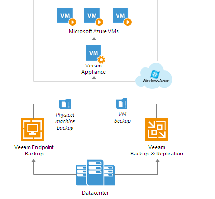
For restore to Microsoft Azure, you can use backups of physical machines created with Veeam Endpoint Backup and backups of VMs created with Veeam Backup & Replication. You can restore machines from backups of Microsoft Hyper-V and VMware vSphere VMs, as well as VMware vCloud Director VMs.
Veeam Direct Restore to Microsoft Azure is delivered as a pre-configured Microsoft Azure appliance.
The appliance runs Veeam Backup & Replication in the free operation mode and the
Veeam Azure Recovery utility that lets you restore machines from backups to the cloud. Veeam Direct Restore to Microsoft Azure
is started immediately and is ready for use when you start the appliance in Microsoft Azure.![About Veeam Direct Restore to Microsoft Azure]()
Limitations for Restore to Microsoft Azure
- The BETA version of Veeam Direct Restore to Microsoft Azure uses the classic deployment model to restore machines. Restored VMs will be available under the Virtual machines (classic) view in the Microsoft Azure portal.
- The BETA version of Veeam Direct Restore to Microsoft Azure lets you restore only Microsoft Windows machines. Restore of Linux machines is not supported.
- The maximum size of one disk for a VM in Microsoft Azure is 1023 GB. You cannot restore a machine that has disks of a greater size. For more information, see https://azure.microsoft.com/en-us/documentation/articles/azure-subscription-service-limits/.
- If the system disk of the initial machine uses the GPT partitioning scheme, the number of partitions on the disk cannot exceed 4. During restore such disk will be converted to a disk using the MBR partitioning scheme.
- [For VM backups] Veeam Direct Restore to Microsoft Azure supports batch restore. To restore several VMs, you should pass through the Restore to Azure wizard several times.
System Requirements
A Microsoft Azure VM that you plan to use as a Veeam appliance must meet the following requirements:
Specification |
Requirement |
|---|
| VM Size | A2 VM size (2 cores, 3.5 GB memory) is minimum, A3 VM size (4 cores, 7 GB memory) is recommended. |
| Hardware | CPU: x86-64 processor.
CPU: 2 cores or more.
Memory: 4 GB RAM.
Disk Space: 2 GB for product installation and 4.5 GB for Microsoft .NET Framework 4.5.2 installation.
Network: 1 Mbps or faster. |
Restoring Machines to Microsoft Azure
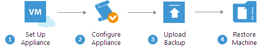
To restore a machine from a backup to Microsoft Azure, you must perform the following steps:
- Deploy the Veeam appliance.
You can deploy a Veeam appliance from the 'Veeam Direct Restore to Microsoft Azure' template in Microsoft Azure. The appliance runs Veeam Backup & Replication in the free operation mode and the Veeam Azure Recovery utility that lets you restore machines from backups to Microsoft Azure.
- Configure the Veeam appliance.
You must provide information about your subscriptions to let Veeam Direct Restore to Microsoft Azure access resources of your subscriptions and make changes to the subscription settings during restore.
- Upload a backup to the Veeam appliance.
You must upload a backup from which you want to restore the machine to the Veeam appliance.
- Restore a machine from the backup.
After you deploy and set up the Veeam appliance, you can restore a machine from the backup to Microsoft Azure.
![Restoring Machines to Microsoft Azure]()
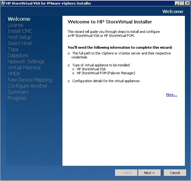
Deploying Veeam Appliance
You can deploy a Veeam appliance from a preconfigured image — Microsoft Azure template named '
'Veeam Direct Restore to Microsoft Azure'. The appliance will run Microsoft Windows 2012 and will have the following software installed:
- Veeam Backup & Replication functioning in the free operational mode
- Veeam Azure Recovery utility
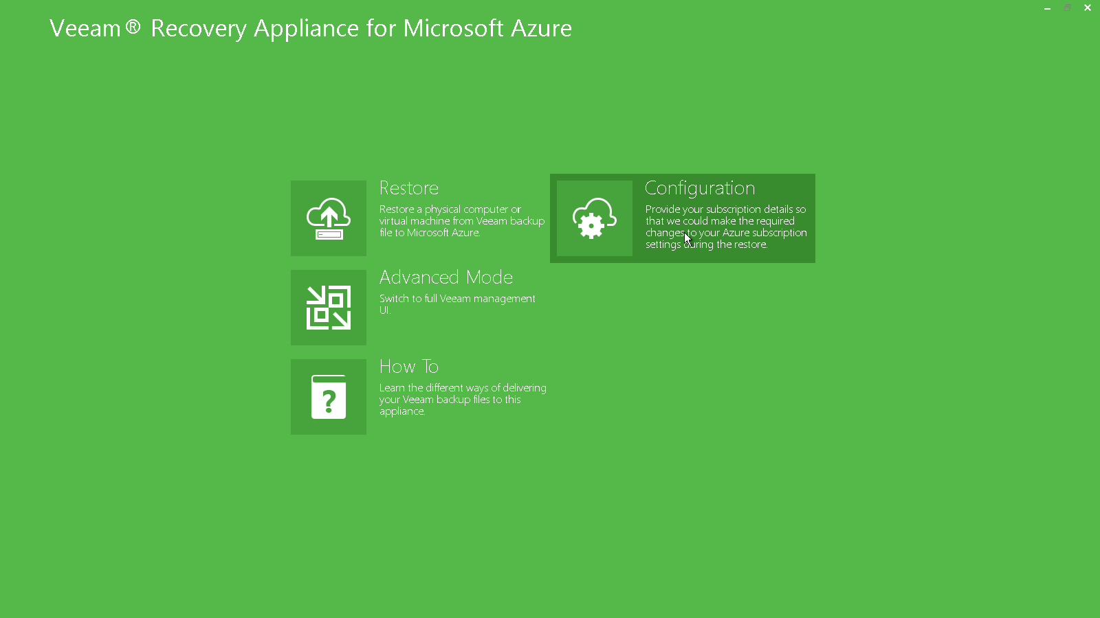
After you deploy and start the Veeam appliance, Veeam Backup & Replication will display its main view. You can use this view to perform basic operations in Veeam Direct Restore to Microsoft Azure.
![Deploying Veeam Appliance]() Note: Note: |
|
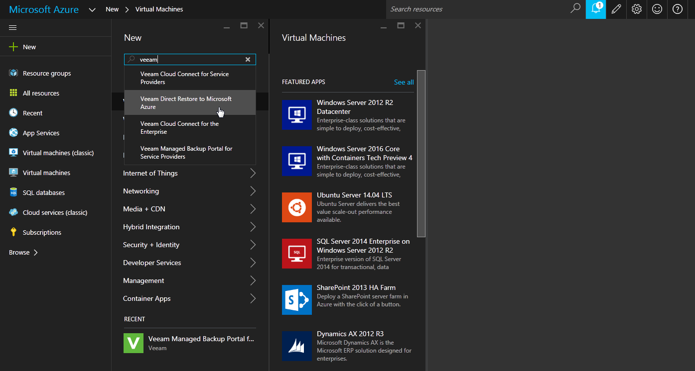
To deploy a Veeam appliance from a Microsoft Azure template:
- Sign in to the Microsoft Azure portal at https://portal.azure.com.
- In the menu on the left, click New.
- In the marketplace, search for the 'Veeam Direct Restore to Microsoft Azure' template.
- Select the template and click Create.
- At the Basics step, configure VM basic settings: VM name, user credentials, subscription, resource group and location.
- At the Size step, choose the VM size.
Make sure that the VM size and configuration meet minimal requirements to the Veeam appliance.
- Review the VM configuration and finish the VM creation procedure.
![Deploying Veeam Appliance]()
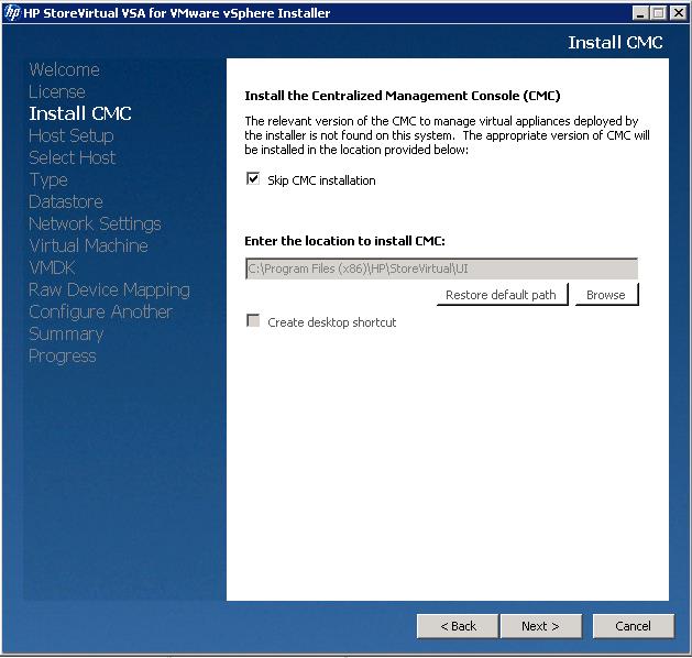
Configuring Veeam Appliance
Before you can restore machines to Microsoft Azure,
you must provide information about your subscriptions to Veeam Direct Restore to Microsoft Azure. This step is required to let Veeam Direct Restore to Microsoft Azure access resources of your subscriptions and make changes in the subscription settings during restore.To provide information about your subscriptions, you must run the
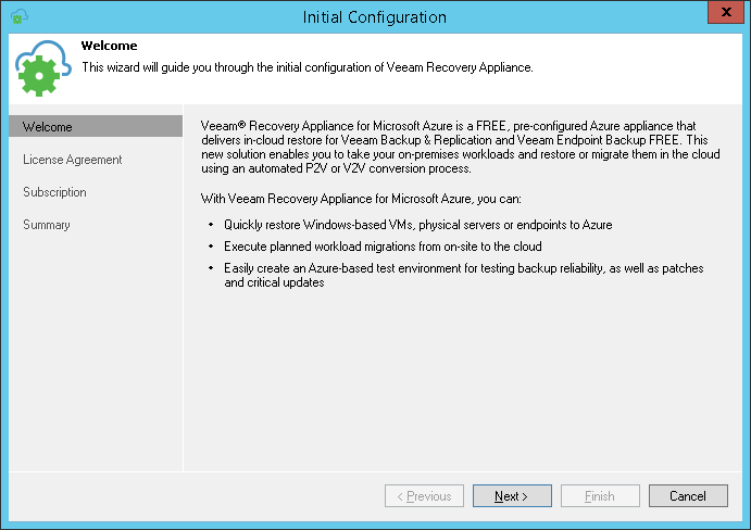
Initial Configuration wizard. The
Initial Configuration wizard lets you download a subscription configuration file from the Microsoft Azure portal and set up it on the Veeam appliance. The subscription configuration file is an XML file in the
PUBLISHSETTINGS format that contains information about all subscriptions associated with your Live ID and a management certificate (the certificate is required to authenticate requests from
Veeam Direct Restore to Microsoft Azure to the Microsoft Windows Azure Management API).
If necessary, you can import to
Veeam Direct Restore to Microsoft Azure several subscription configuration files for different user accounts. In this case, you will be able to use resources of all subscriptions under these user accounts to restore machines to Microsoft Azure.
Information about your subscriptions and the management certificate is saved to the Veeam Backup & Replication database. You can re-import the subscription configuration file at any time. To do this, you must pass through the
Initial Configuration wizard once again.
![Configuring Veeam Appliance]() Note: Note: |
When you download a subscription configuration file from the Microsoft Azure portal, Microsoft Azure always generates a new management certificate. The number of management certificates is limited — you cannot create more than 10 management certificates per one subscription or 100 management certificates per all subscriptions under one service administrator’s user ID. If the number of management certificates has reached this limit, you can re-use existing certificates or create an account for a co-administrator who will be able to create new management certificates.
|
To download a subscription configuration file and set up it on the Veeam appliance:
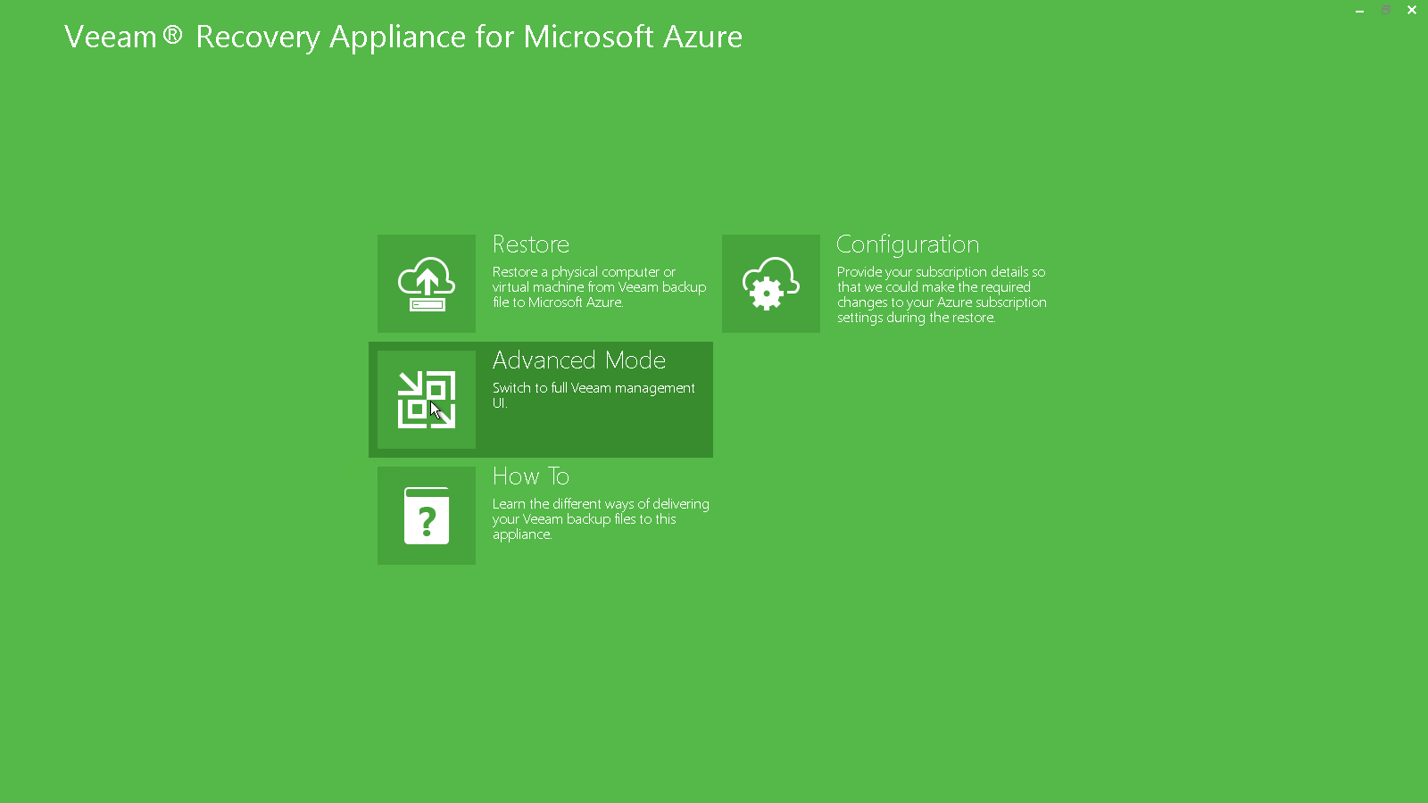
- On the main screen of Veeam Direct Restore to Microsoft Azure, click Configuration.
- The Initial Configuration wizard will be launched. Click Next.
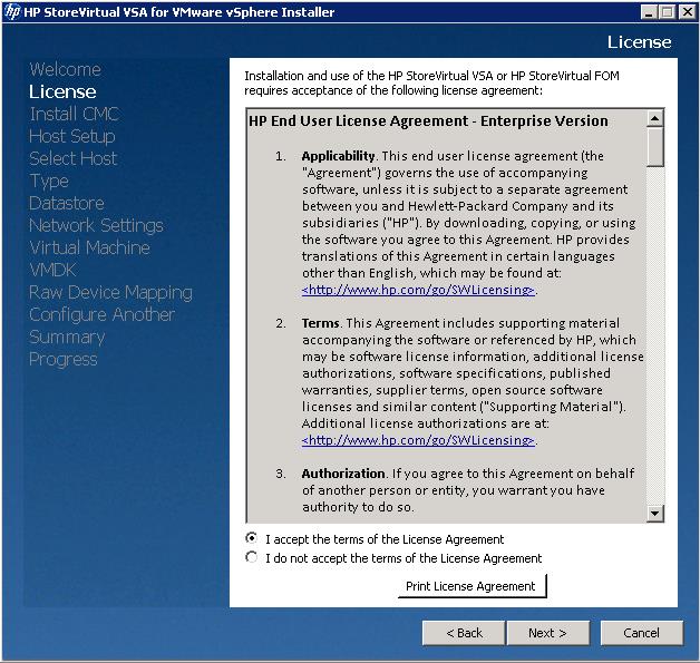
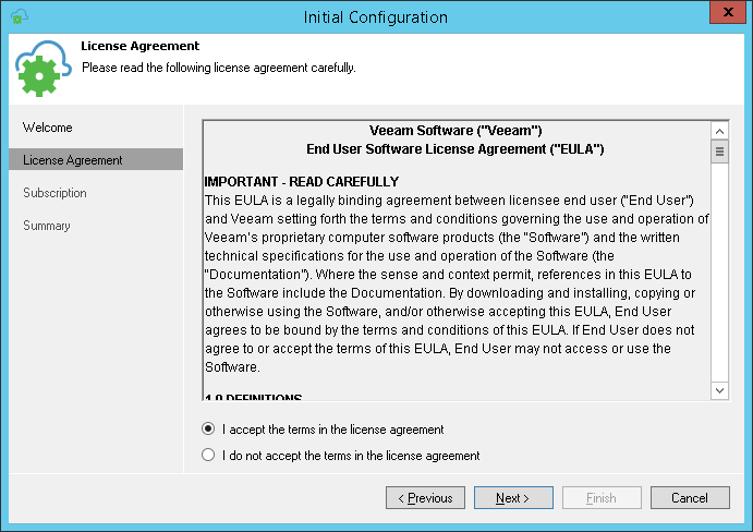
- At the License Agreement step of the wizard, select the I accept the terms in the license agreement option and click Next.
The License Agreement step is displayed only when you configure settings for the first time. If you decide to re-import the subscription configuration file later, the License Agreement step will be skipped.
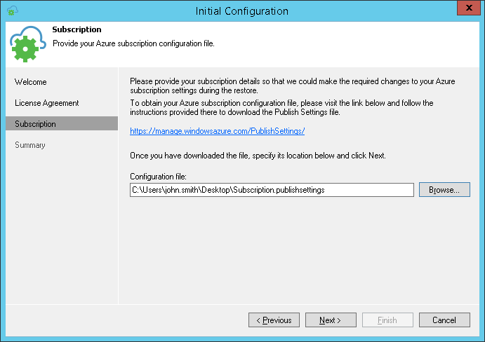
- At the Subscription step of the wizard, click the https://manage.windowsazure.com/PublishSettings link. If you are not logged in to the Microsoft Azure portal, you will be prompted to log in.
Microsoft Azure will generate a subscription configuration file and offer you to download it when the file is ready. Save the file to a local drive on your computer or network shared folder.
- Next to the Configuration file field, click Browse and select the saved file. Click Next.
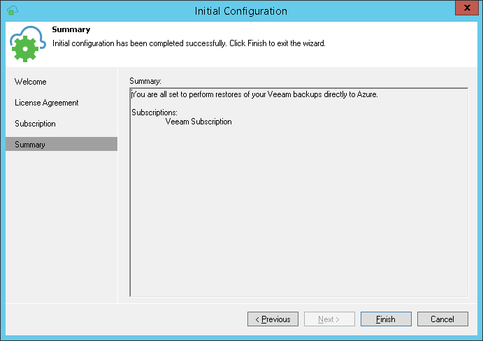
- At the Summary step of the wizard, review details of the configured settings and click Finish to close the wizard.
Uploading Backups to Veeam Appliance
Before you can start restoring machines to Microsoft Azure, you need to upload backups to the Veeam appliance hosting Veeam Direct Restore to Microsoft Azure. You can use the following tools and methods to upload backups:
- Veeam FastSCP for Microsoft Azure
- Azure File Storage
- Remote Desktop Connection
- Attaching VM Disk
- FTP Server
Veeam FastSCP for Microsoft Azure (Recommended)
Veeam FastSCP for Microsoft Azure is a standalone free solution that allows you to upload and download data to and from Microsoft Azure VMs. With this solution, you can easily copy files securely from onsite to Microsoft Azure VMs and vice versa.
To download Veeam FastSCP for Microsoft Azure, use the following link:
https://www.veeam.com/fastscp-azure-vm-download.htmlVeeam FastSCP for Microsoft Azure requires that PowerShell Remoting is enabled and configured on the Microsoft Azure VM. When you deploy the Microsoft Azure VM in the Resource Manager deployment model, PowerShell Remoting is not enabled automatically. To take the advantage of Veeam FastSCP for Microsoft Azure, you will need to enable PowerShell Remoting manually first. To do this, follow
these recommendations.
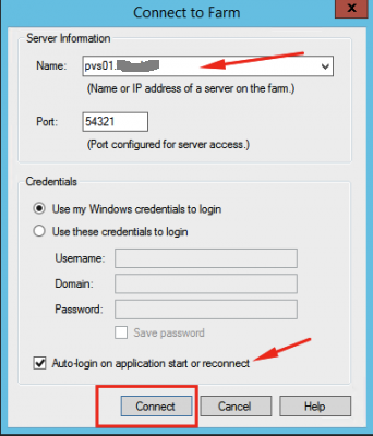
Adding Azure VMsBefore you upload backups to the Veeam Direct Restore to Microsoft Azure appliance, you need to connect the Veeam appliance to Veeam FastSCP for Microsoft Azure:
- In Veeam FastSCP for Microsoft Azure, open the Virtual Machines view.
- Click Add Machine on the ribbon.
- In the Host field, type a DNS name of the cloud service where the Veeam appliance resides. Alternatively, you can type a public virtual IP address of the cloud service.
- In the Port field, type the number of a public port configured for the PowerShell Remoting endpoint on the Veeam appliance.
- In the Username and Password fields, specify credentials of the local Administrator on the Veeam appliance.
The username must be specified in the DOMAIN\USERNAME format for domain accounts or HOST\USERNAME for local accounts.
Check information regarding the VM service DNS name or virtual IP address and public port configured for the PowerShell Remoting endpoint in the Microsoft Azure portal.
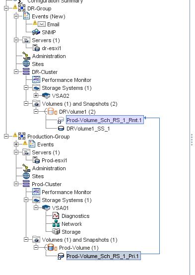
- Cloud Service (Host) : Virtual Machines> Veeam Azure RecoveryVM> DNS name
- Endpoint (Port): Virtual Machines> Veeam Azure Recovery VM> Endpoints
Uploading One or More Files ManuallyYou can manually upload to the Veeam appliance one file or several files that reside in the same folder:
- In Veeam FastSCP for Microsoft Azure, open the Virtual Machines view.
- In the Machines list on the left, choose the newly added Veeam appliance, expand its folder tree and select a folder to which you want to upload files.
- Click Upload Files on the ribbon.
- In the Open window, browse to the files that you want to upload, select them and click Open (for multiselect hold [CTRL] or [SHIFT]).
- When upload is completed, right-click anywhere in the right pane and choose Refresh to view an updated list of files in the folder.
Uploading One or More Files AutomaticallyYou can upload files with scheduled jobs. Scheduled jobs allow you to automate the upload process and upload backup files to the Veeam appliance on a fixed schedule.
To create a scheduled job, navigate to the
Jobs tab in Veeam FastSCP for Microsoft Azure.
Microsoft Azure File Storage
Microsoft Azure File Storage is a service that offers file shares in the cloud using the standard Server Message Block (SMB) Protocol. Both SMB 2.1 and SMB 3.0 are supported.
- Sign in to the Microsoft Azure portal.
- On the navigation menu, click Storage accounts.
- Choose your storage account.
- Choose Files service
- Click File shares and fill in the file share name and size of the file share (up to 5120 GB) to create your first file share.
Connecting share- Choose the file share you have already created.
- Click Connect.
- Copy the resulting command.
- Run the command from any Microsoft Windows machine to mount the file share.
Once the share is mounted, you can start uploading and downloading files to and from it.
![Uploading Backups to Veeam Appliance]() Note: Note: |
You can also upload and download files residing on the Microsoft Azure File Storage using the Microsoft Azure portal (Upload and Download buttons). However, you can use this method only to deliver files of considerably small size.
|
Remote Desktop Connection
Remote Desktop Protocol (RDP) is a proprietary protocol developed by Microsoft that provides a user with a graphical interface to connect to another computer over a network connection.
- Sign in to the Microsoft Azure portal.
- Select the Veeam appliance.
- Press the Connect button to download an RDP file. You can use this file to connect to the Veeam appliance.
Now you can copy files from your local computer to Veeam Azure Recovery VM over the RDP protocol. Be aware that by default RDP protocol does not allow copying files that are larger than 2 GB:
https://support.microsoft.com/en-us/kb/2258090.
To overcome this limitation, you can configure Drive Redirection:
- Right-click the RDP file you have downloaded and choose Edit.
- Go to the Local Resources tab and click More… in the Local devices and resources section.
- Select the device that you want to map to your remote session.
Now you can see the mapped drive in Windows Explorer as a connected drive and copy files to it.
Attaching VM Disk
You can create an empty VHD disk onsite and copy backup data to this disk.
To create a VHD disk:
- Go to Administrative Tools& Computer Management& Disk Management.
- Right-click Disk management and select Create VHD. Make sure that you select VHD; VHDX is not supported by Microsoft Azure.
Once a VHD is created, it will be automatically attached to your computer. You should initialize, format and assign a drive letter to it. After that you can copy/move backup files to it.
When the required data is copied, you should upload the VHD to your Microsoft Azure account. For more information, see
http://azure.microsoft.com/en-us/documentation/articles/virtual-machines-create-upload-vhd-windows-server/.
![Uploading Backups to Veeam Appliance]() Note: Note: |
|
Next, you need to attach the disk to the VM appliance.
- Sign in to the Microsoft Azure portal.
- In the menu on the left, click Virtual Machines.
- Select the VM appliance from the list.
- At the bottom right corner of the Essentials blade, click All settings> Disks.
- On the Disks blade, click Attach existing.
- Under Attach existing disk, click VHD File.
- Under Storage accounts, select the account and container that holds the VHD file.
- Select the VHD file.
- The file you have just selected will be listed under Attach existing disk > VHD File. Click OK.
- After Microsoft Azure attaches the disk to the Veeam appliance, the disk will be listed in the VM disk settings under Data Disks.
After the disk is added, you need to prepare it for use in the VM OS. For more information, see
How to: initialize a new data disk in Windows Server. After that, you will be able to see this disk in Windows Explorer and get backup files from this disk.
FTP Server
This method requires that you install a solution into the Veeam appliance, which is probably something you don’t want to do frequently.
You can install an FTP server in the Veeam appliance and configure it to use the passive mode and a single port range (multiple-port range is possible, but this can create additional overhead). After that, you can add endpoints to the Veeam appliance to open the firewall ports.
Restoring Machines
For restore to Microsoft Azure, you can use backups of physical machines created with Veeam Endpoint Backup and backups of Microsoft Windows VMs created with Veeam Backup & Replication. You can restore a machine to the latest state or any previous restore point in the backup chain. After you restore the machine from the backup, the machine appears in the Microsoft Azure portal, and you can use it as a regular Microsoft Azure VM.
Restoring Machines Important!
After the restore process is finished, Veeam Direct Restore to Microsoft Azure immediately powers on the restored VM.
Before you restore the machine from the backup, check prerequisites. Then use the Restore to Azure wizard to restore the machine.
- Launch the Restore to Azure wizard
- Select a machine to restore
- Select a subscription and location
- Specify a VM size
- Specify a machine name and cloud service
- Select a virtual network
- Specify a restore reason
- Review the restore summary
- Review the restore process
Before You Begin
Before you restore a machine to Microsoft Azure, check the following prerequisites:
- You must deploy the Veeam appliance in Microsoft Azure.
- You must provide information about your subscriptions to Veeam Direct Restore to Microsoft Azure.
- You must upload a backup from which you want to restore the machine to the Veeam appliance.
- You must check limitations for Veeam Direct Restore to Microsoft Azure.
Step 1. Choose Backup File
To begin the restore process, you must choose a backup from which you can restore the machine:
- On the main screen of Veeam Direct Restore to Microsoft Azure, click Restore.
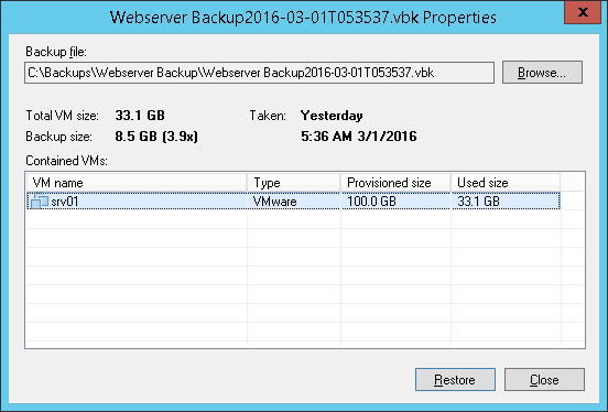
- In the Select backup file to restore window, click Browse next to the Backup file field and select a full backup file (VBK) or backup metadata file (VBM) from the uploaded backup chain.
If you select the VBM file, the import process will be notably faster. It is recommended that you select the VBK file only if the VBM file is not available.
- In the Backup Properties window, select the machine that you want to restore to Microsoft Azure.
- Click Restore.
![Step 1. Choose Backup File]() Tip: Tip: |
To launch the Restore to Azure wizard, you can also double-click the full backup file (VBK) in the file browser on the Veeam appliance. Veeam Backup & Replication will start its console and display the Backup Properties window. In the Backup Properties window, select the machine and click Restore > Azure.
|
![Step 1. Choose Backup File]()
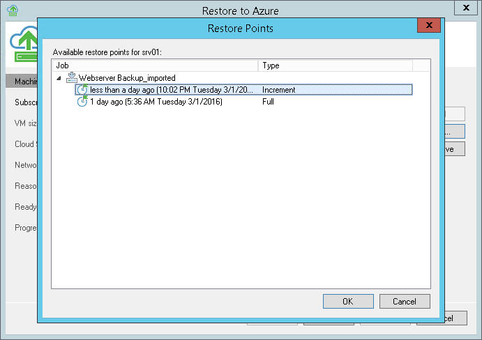
Step 2. Select Restore Point
At the
Machine step of the wizard, you can select the restore point to which you want to recover the machine.
By default, Veeam Direct Restore to Microsoft Azure recovers the machine to latest valid restore point in the backup chain. However, you can recover the machine to an earlier restore point.
![Step 2. Select Restore Point]() Tip: Tip: |
The Machine step of the wizard is skipped when you start the Restore to Azure wizard. To select the necessary restore point, you must get back to this step from the Subscription step of the wizard.
|
To select a restore point for the machine:
- In the Object to restore list, select the machine.
- Click Point on the right.
- In the Restore Points window, select a restore point to which you want to recover the machine.
![Step 2. Select Restore Point]()
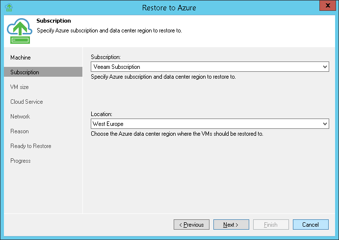
Step 3. Select Subscription and Location
At the
Subscription step of the wizard, you must select a subscription whose resources you want to use, and a location for the recovered machine.
- From the Subscription list, select a subscription whose resources you want to use. The subscription list is formed based on the information from the imported subscription configuration file and contains all subscriptions associated with your Live ID.
- From the Locations list, select a geographic region to which you want to place the recovered machine. Make sure that you select a geographic region with which at least one storage account of your subscription is associated.
![Step 3. Select Subscription and Location]()
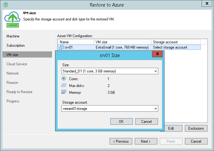
Step 4. Specify VM Size
At the
VM Size step of the wizard, you can:
- Specify the size and storage profile for the recovered machine
- Restore only specific disks for the recovered machine
To specify the size and storage account for the machine:
- In the AzureVM Configuration list, select the machine and click Edit.
- From the Size list, select a size for the recovered VM. The VM size affects the number of CPU cores, memory and disk resources that will be allocated to the recovered machine. For more information about size of VMs in Microsoft Azure, see https://azure.microsoft.com/en-us/documentation/articles/virtual-machines-size-specs/.
- From the Storage account list, select the storage account whose resources you want to use to store VM disks.
- Click OK.
![Step 4. Specify VM Size]() Note: Note: |
Microsoft Azure subscriptions have default limits on the number of CPU cores. Make sure that the VM size you select does not exceed limits of your subscription.
|
![Step 4. Specify VM Size]()
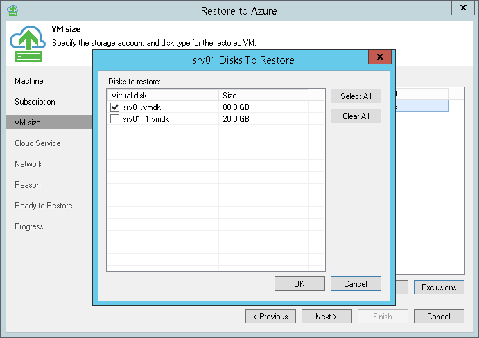
If necessary, you can restore only specific disks for the machine:
- In the AzureVM Configuration list, select the machine and click Exclusions.
- In the Disks to Restore window, select check boxes next to machine disks that you want to restore.
![Step 4. Specify VM Size]()
Step 5. Specify VM Name and Cloud Service
At the
Cloud Service step of the wizard, you can:
- Specify a new name for the recovered machine
- Select a cloud service for the recovered machine
By default, Veeam Direct Restore to Microsoft Azure restores a machine with its original name. However, you can define a new name for the recovered machine if necessary.
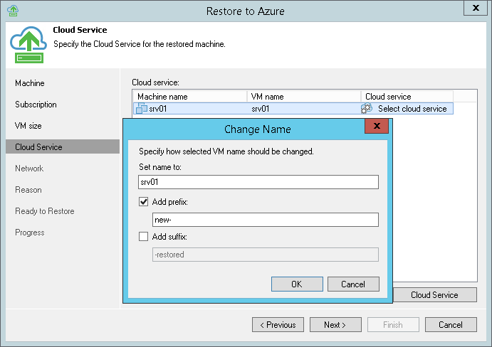
To define a name for the machine:
- In the Cloud service list, select the machine and click VM Name.
- In the Change Name window, enter a new name explicitly or specify a change name rule by adding a prefix and/or suffix to the original machine name.
![Step 5. Specify VM Name and Cloud Service]() By default, Veeam Direct Restore to Microsoft Azure creates a new cloud service for the recovered machine and places the machine to it. If necessary, you can place the machine to an existing cloud service.
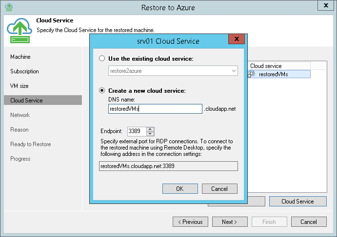
By default, Veeam Direct Restore to Microsoft Azure creates a new cloud service for the recovered machine and places the machine to it. If necessary, you can place the machine to an existing cloud service.- In the Cloud service list, select the machine and click Cloud Service.
- In the Cloud Service window, select the necessary option for the machine:
- Select Choose the existing cloud service if you want to place the machine to an existing cloud service. From the list below, select the cloud service.
- Select Create a new cloud service if you want to create a dedicated cloud service for the machine. In the DNS name field, enter a name of the cloud service that you want to create. The cloud service name can be up to 64 characters long, must start with a letter and can contain only alphanumeric characters and underscores.
- Veeam Direct Restore to Microsoft Azureautomatically creates a Remote Desktop endpoint for the recovered machine. In the Endpoint field, specify the number of a public TCP port for this endpoint. You will be able to access the recovered machine over this port.
By default, Veeam Direct Restore to Microsoft Azure uses port 3389 for Microsoft Windows VMs. Microsoft Azure automatically sets up firewall configuration for ports associated with Remote Desktop.
![Step 5. Specify VM Name and Cloud Service]() Note: Note: |
Microsoft Azure subscriptions have default limits on the number of cloud services. If you decide to create a new cloud service, make sure that you do not exceed limits of your subscription.
|
![Step 5. Specify VM Name and Cloud Service]()
Step 6. Select Virtual Network
At the
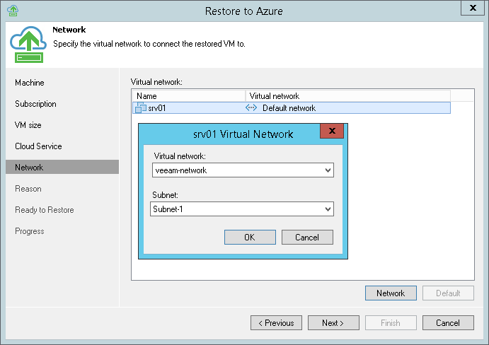
Network step of the wizard, you can select to which network and subnet the recovered machine must be connected.
Veeam Direct Restore to Microsoft Azure can connect the machine only to one virtual network. If necessary, you can configure additional network connections after the machine is recovered.
To define network settings for the VM:
- In the Virtual network list, select the machine and click Network.
- From the Virtual network list, select a network to which the machine must be connected.
- From the Subnet list, select a subnet for the machine.
To connect the machine to the default network of the target cloud service, select the machine in the
Virtual network list and click
Default.
![Step 6. Select Virtual Network]()
Step 7. Specify Restore Reason
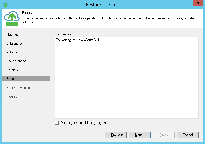
At the
Reason step of the wizard, enter a reason for restoring the machine. The information you provide will be saved in the session history in Veeam Backup & Replication, and you can reference it later.
![Step 7. Specify Restore Reason]() Tip: Tip: |
If you do not want to display the Reason step of the wizard in future, select the Do not show me this page again check box.
|
![Step 7. Specify Restore Reason]()
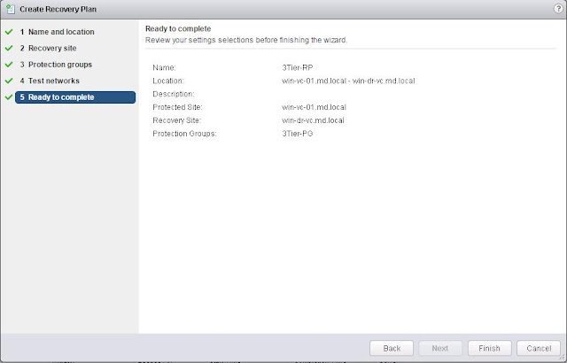
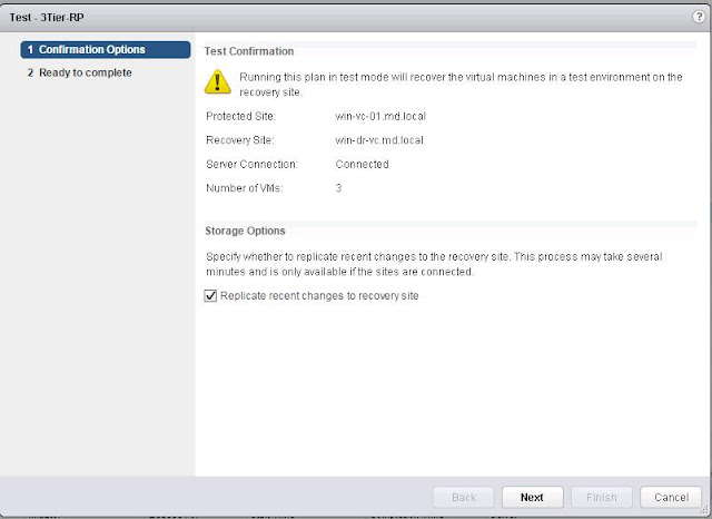
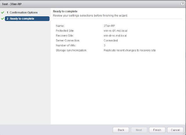
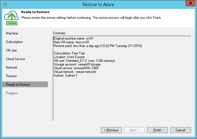
Step 8. Review Restore Summary
At the
Ready to Restore step of the wizard, check the specified settings and click
Finish. Veeam Direct Restore to Microsoft Azure will start the restore process.
![Step 8. Review Restore Summary]()
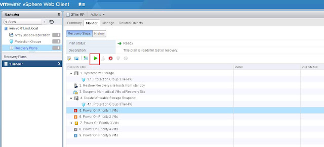
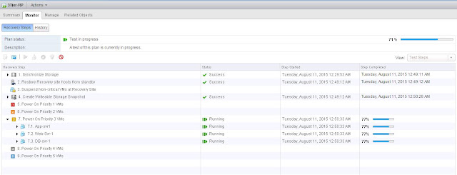
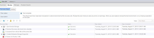
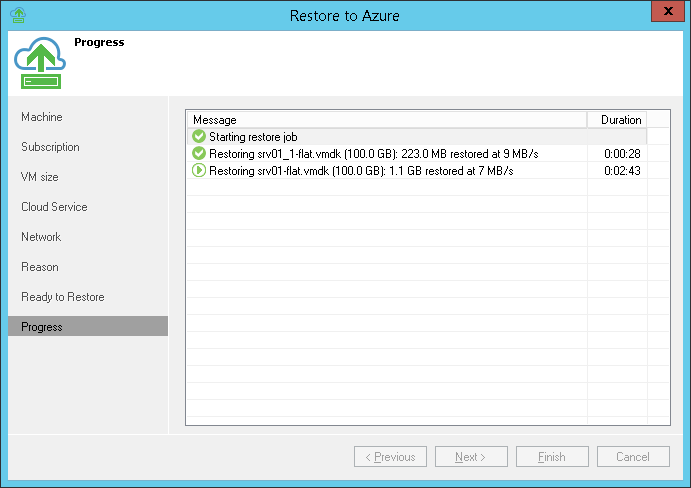
Step 9. Review Restore Process
At the
Progress step of the wizard, you can trace the restore process in the real-time mode.
![Step 9. Review Restore Process]()
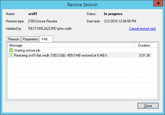
You can also use the
Restore Session window to trace the restore process. If you need to cancel the machine restore, click the
Cancel restore task link in the
Restore Session window.
![Step 9. Review Restore Process]()
Using Advanced Mode
If necessary, you can use the main Veeam Backup & Replication UI to restore machines to Microsoft Azure. To start the Veeam Backup & Replication console, o
n the main screen of Veeam Direct Restore to Microsoft Azure, click Advanced Mode. Veeam Direct Restore to Microsoft Azure will launch the Veeam Backup & Replication console; the product will run in the free functionality mode.![Using Advanced Mode]()


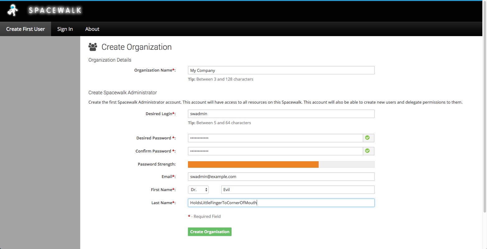 You are now able to start using Spacewalk.