Veeam Backup & Replication provides a set of features for building and maintaining a flexible backup infrastructure, performing data protection tasks (such as VM backup, replication, copying backup files), and carrying out disaster recovery procedures. This article contains a high-level step by step guide of Veeam Backup & Replication, its architecture, features, data protection and disaster recovery concepts necessary to understand Veeam Backup & Replication background operations and processes.
Solution Architecture
Veeam Backup & Replication is a modular solution that lets you build a scalable backup infrastructure for environments of different sizes and configuration. The installation package of Veeam Backup & Replication includes a set of components that you can use to configure the backup infrastructure. Some components are mandatory and provide core functionality; some components are optional and can be installed to provide additional functionality for your business and deployment needs.
You can co-install Veeam Backup & Replication components on the same machine, physical or virtual, or you can set them up separately for a more scalable approach.
Components
The Veeam backup infrastructure comprises a set of components. Some components can be deployed with the help of the setup file. Other components can be deployed via the Veeam Backup & Replication console.
Backup Server
The backup server is a Windows-based physical or virtual machine on which Veeam Backup & Replication is installed. It is the core component in the backup infrastructure that fills the role of the “configuration and control center”. The backup server performs all types of administrative activities:
- Coordinates backup, replication, recovery verification and restore tasks
- Controls job scheduling and resource allocation
- Is used to set up and manage backup infrastructure components as well as specify global settings for the backup infrastructure
In addition to its primary functions, a newly deployed backup server also performs the role of the default backup repository, storing backups locally.
The backup server uses the following services and components:
- Veeam Backup Service is a Windows service that coordinates all operations performed by Veeam Backup & Replication such as backup, replication, recovery verification and restore tasks. The Veeam Backup Service runs under the Local System account or account that has the Local Administrator permissions on the backup server.
- Veeam Backup & Replication Console provides the application user interface and allows user access to the application's functionality.
- Veeam Guest Catalog Service is a Windows service that manages guest OS file system indexing for VMs and replicates system index data files to enable search through guest OS files. Index data is stored in the Veeam Backup Catalog — a folder on the backup server. The Veeam Guest Catalog Service running on the backup server works in conjunction with search components installed on Veeam Backup Enterprise Manager and (optionally) a dedicated Microsoft Search Server.
- Veeam Backup & Replication Configuration Database is used to store data about the backup infrastructure, jobs, sessions and so on. The database instance can be located on a SQL Server installed either locally (on the same machine where the backup server is running) or remotely.
- Veeam Backup PowerShell Snap-In is an extension for Microsoft Windows PowerShell 2.0. Veeam Backup PowerShell adds a set of cmdlets to allow users to perform backup, replication and recovery tasks through the command-line interface of PowerShell or run custom scripts to fully automate operation of Veeam Backup & Replication.
- Mount server is a component required for browsing the VM guest file system and restoring VM guest OS files and application items to the original location.
Backup & Replication Console
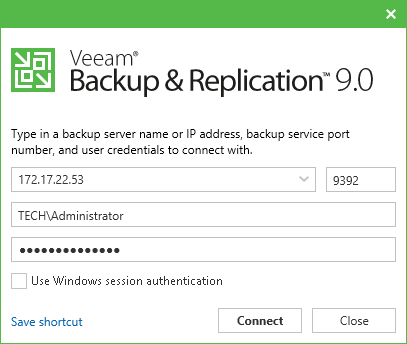
The Veeam Backup & Replication console is a separate client-side component that provides access to the backup server. The console is installed locally on the backup server by default. You can also use it in a standalone mode — install the console on a dedicated machine and access Veeam Backup & Replication remotely over the network. The console lets you log in to Veeam Backup & Replication and perform all kind of data protection and disaster recovery operations as if you work on the backup server.
To log in to Veeam Backup & Replication via the console, the user must be added to the Local Users group on the backup server or a group of domain users who have access to the backup server. The user can perform the scope of operations permitted by his or her role in Veeam Backup & Replication.
You can install as many remote consoles as you need so that multiple users can access Veeam Backup & Replication simultaneously. Veeam Backup & Replication prevents concurrent modifications on the backup server. If several users are working with Veeam Backup & Replication at the same time, the user who saves the changes first has the priority. Other users will be prompted to reload the wizard or window to get the most recent information about the changes in the configuration database.
If you have multiple backup servers in the infrastructure, you can connect to any of them from the same console. For convenience, you can save several shortcuts for these connections.
To make users' work as uninterrupted as possible, the remote console maintains the session for 5 minutes if the connection is lost. If the connection is re-established within this period, you can continue working without re-logging to the console.
When you install a remote console on a machine, Veeam Backup & Replication installs the following components:
- Veeam Backup PowerShell Snap-In
- Veeam Explorer for Microsoft Active Directory
- Veeam Explorer for Microsoft Exchange
- Veeam Explorer for Oracle
- Veeam Explorer for Microsoft SQL
- Veeam Explorer for Microsoft SharePoint
- Mount server
The console does not have a direct access to the backup infrastructure components and configuration database. Such data as user credentials, passwords, roles and permissions are stored on the backup server side. To access this data, the console needs to connect to the backup server and query this information periodically during the work session.
![Backup & Replication Console]()
Requirements and Limitations for Remote Console
The machine on which you install the Veeam Backup & Replication console must meet the following requirements:
- The remote console can be installed on a Microsoft Windows machine (physical or virtual).
- If you install the console remotely, you can deploy it outside NAT. However, the backup server must be behind NAT. The opposite type of deployment is not supported: if the backup server is deployed outside NAT and the remote console is deployed behind NAT, you will not be able to connect to the backup server.
The Veeam Backup & Replication console has the following limitations:
- You cannot perform restore from the configuration backup via the remote console.
- The machines on which the remote console is installed are not added to the list of managed servers automatically. For this reason, you cannot perform some operations, for example, import backup files that reside on the remote console machine or assign roles of backup infrastructure components to this machine. To perform these operations, you must add the remote console machine as a managed server to Veeam Backup & Replication.
Off-Host Backup Proxy
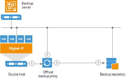
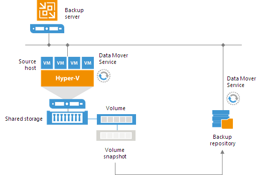
By default, when you perform backup and replication jobs in the Hyper-V environment, VM data is processed directly on the source Hyper-V host where VMs reside, and then moved to the target, bypassing the backup server.
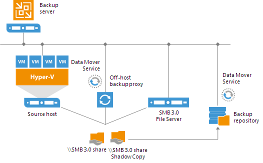
VM data processing can produce unwanted overhead on the production Hyper-V host and impact performance of VMs running on this host. To take data processing off the production Hyper-V host, you can use the off-host backup mode.
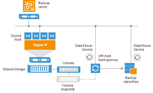
The off-host mode shifts the backup and replication load to a dedicated machine — an off-host backup proxy. The off-host backup proxy functions as a “data mover” which retrieves VM data from the source datastore, processes it and transfers to the destination.
The machine performing the role of an off-host backup proxy must meet the following requirements:
- The role of an off-host backup proxy can be assigned only to a physical Microsoft Windows 2008 Server R2 machine with the Hyper-V role enabled, Windows Server 2012 machine with the Hyper-V role enabled or Windows Server 2012 R2 machine with the Hyper-V role enabled.
For evaluation and testing purposes, you can assign the off-host backup proxy role to a VM. To do this, you must enable the Hyper-V role on this VM (use nested virtualization). However, it is not recommended that you use such off-host backup proxies in the production environment.
- The off-host backup proxy must have access to the shared storage where VMs to be backed up, replicated or copied are hosted.
- To create and manage volume shadow copies on the shared storage, you must install a VSS hardware provider that supports transportable shadow copies on the off-host proxy and the Hyper-V host. The VSS hardware provider is usually distributed as a part of client components supplied by the storage vendor.
When you assign the role of an off-host backup proxy to the selected machine, Veeam Backup & Replication automatically installs on it light-weight components and services required for backup proxy functioning. Unlike the backup server, backup proxies do not require a dedicated SQL database — all settings are stored centrally, within the configuration database used by Veeam Backup & Replication.
To enable a Hyper-V host or a Windows machine to act as an off-host backup proxy,
Veeam Backup & Replication installs the following services on it:
- Veeam Installer Service is an auxiliary service that is installed and started on any Windows (or Hyper-V) server once it is added to the list of managed servers in the Veeam Backup & Replication console. This service analyzes the system, installs and upgrades necessary components and services.
- Veeam Transportis responsible for deploying and coordinating executable modules that act as "data movers" and perform main job activities on behalf of Veeam Backup & Replication, such as performing data deduplication, compression and so on.
- Veeam Hyper-V Integration Service is responsible for communicating with the VSS framework during backup, replication and other jobs, and performing recovery tasks. The service also deploys a driver that handles changed block tracking for Hyper-V.
Guest Interaction Proxy
To interact with the VM guest OS during the backup or replication job, Veeam Backup & Replication needs to deploy a runtime process in each VM. Guest OS interaction is performed if you enable the following options in the job:
- Application-aware processing
- Guest file system indexing
- Transaction logs processing
Previously, the runtime process on all VMs was deployed by the backup server. This could cause the following problems:
- The load on the backup server was high.
- If a connection between two sites was slow, the job performance decreased.
- If the backup server had no network connection to VMs, application-aware processing tasks were not accomplished for these VMs.
![Guest Interaction Proxy]()
Starting from Veeam Backup & Replication 9.0, the task of deploying the runtime process in a Microsoft Windows VM is performed by the guest interaction proxy. The guest interaction proxy is a backup infrastructure component that sits between the backup server and processed VM. The guest interaction proxy deploys the runtime process in the VM and sends commands from the backup server to the VM.
The guest interaction proxy allows you to communicate with the VM guest OS even if the backup server and processed VM run in different networks. As the task of runtime process deployment is assigned to the guest interaction proxy, the backup server only has to coordinate job activities.
![Guest Interaction Proxy]() Important! Important! |
The guest interaction proxy deploys the runtime process only in Microsoft Windows VMs. In VMs with another guest OS, the runtime process is deployed by the backup server.
|
![Guest Interaction Proxy]()
You can use multiple guest interaction proxies to improve performance. Multiple guest interaction proxies will deploy runtime processes in VMs faster compared to the same operation performed by one guest interaction proxy.
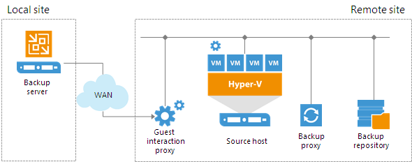
In a backup infrastructure with multiple remote sites, you can deploy a guest interaction proxy in each site. This can reduce load on the backup server and produce less traffic between the backup server and remote site. The backup server will only have to send commands to the guest interaction proxies.
Requirements for Guest Interaction Proxy
To perform the role of guest interaction proxy, the machine must meet the following requirements:
- It must be a Microsoft Windows machine (physical or virtual).
- You must add it to the Veeam Backup & Replication console as a managed server.
- It must have a LAN connection to the VM that will be backed up or replicated.
The guest interaction proxy role can be performed by any machine that meets the requirements, including backup proxy, backup repository, WAN accelerator, Microsoft Hyper-V host or backup server.
![Guest Interaction Proxy]() Note: Note: |
The guest interaction proxy functionality is available in the Enterprise and Enterprise Plus Editions of Veeam Backup & Replication.
|
Guest Interaction Proxy Selection
When you add a Microsoft Windows machine to the backup infrastructure, Veeam Backup & Replication deploys the Data Mover Service on it. The Data Mover Service includes the components responsible for runtime process deployment during guest OS interaction.
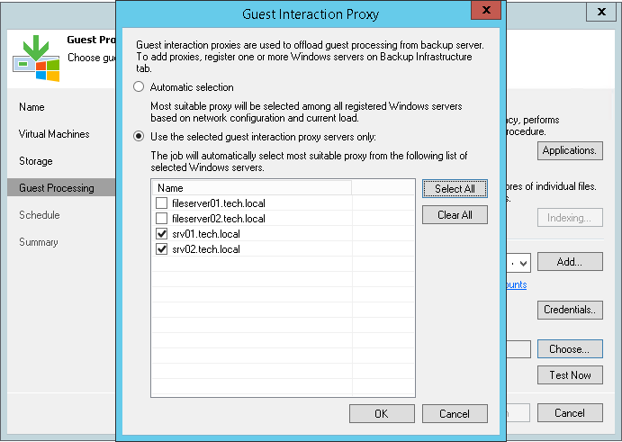
To assign a guest interaction proxy for the job, you must select a Microsoft Windows machine that will perform the role of the guest interaction proxy at the
Guest Processing step of the backup or replication job wizard. You can assign the guest interaction proxy manually, or let Veeam Backup & Replication do it automatically. Veeam Backup & Replication uses the following priority rules to select the guest interaction proxy:
- A machine in the same network as the protected VM that does not perform the backup server role.
- A machine in the same network as the protected VM that performs the backup server role.
- A machine in another network that does not perform the backup server role.
- A machine in another network that performs the backup server role.
If Veeam Backup & Replication finds several available machines of equal priority, it selects the less loaded machine. The load is defined by the number of tasks that the machine already performs.
Failover from Guest Interaction Proxy to Backup Server
If the guest interaction proxy fails to connect to a Microsoft Windows VM, the guest interaction proxy will not be able to access the VM and deploy a runtime process in it. In this case, the backup server will take over the role of guest interaction proxy and deploy the runtime process in the VM.
Backup Repository
A backup repository is a storage location where you can keep backup files and metadata for replicated VMs. You can configure the following types of backup repositories in the backup infrastructure:
Simple Backup Repository
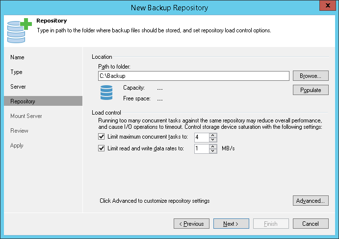
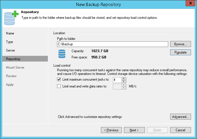
A backup repository is a location used by Veeam Backup & Replication jobs to store backup files.
Technically, a backup repository is a folder on the backup storage. By assigning different repositories to jobs and limiting the number of parallel jobs for each one, you can balance the load across your backup infrastructure.
In the Veeam backup infrastructure, you can use one of the following repository types:
- Microsoft Windows server with local or directly attached storage. The storage can be a local disk, directly attached disk-based storage (such as a USB hard drive), or iSCSI/FC SAN LUN in case the server is connected into the SAN fabric.
On a Windows repository, Veeam Backup & Replication deploys a local Veeam Data Mover Service (when you add a Windows-based server to the product console, Veeam Backup & Replication installs a set of components including the Veeam Data Mover Service on that server). When any job addresses the backup repository, the Veeam Data Mover Service on the backup repository establishes a connection with the source-side Veeam Data Mover Service on the backup proxy, enabling efficient data transfer over LAN or WAN. - Linux server with local, directly attached storage or mounted NFS. The storage can be a local disk, directly attached disk-based storage (such as a USB hard drive), NFS share, or iSCSI/FC SAN LUN in case the server is connected into the SAN fabric.
When any task addresses a Linux repository, Veeam Backup & Replication deploys and starts the Veeam Data Mover Service on the backup repository. The Data Mover Service establishes a connection with the source-side Data Mover Service on the backup proxy, enabling efficient data transfer over LAN or WAN.
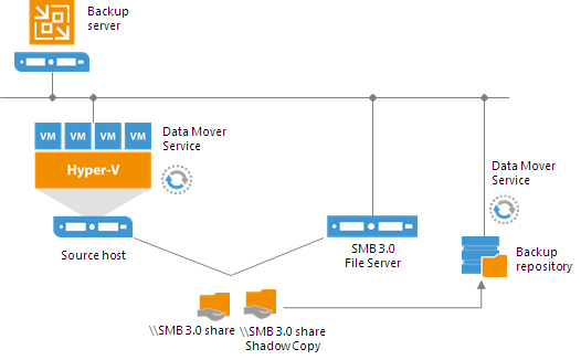
- CIFS (SMB) share. SMB share cannot host Veeam Data Mover Services. For this reason, data to the SMB share is written from the gateway server. By default, this role performs an on-host or off-host backup proxy that is used by the job for data transport.
However, if you plan to move VM data to an offsite SMB repository over a WAN link, it is recommended that you deploy an additional gateway server in the remote site, closer to the SMB repository.
Veeam Backup & Replication will deploy a Veeam Data Mover Service on this gateway server, which will improve data transfer performance.
- Deduplicating storage appliance. Veeam Backup & Replication supports the following deduplicating storage appliances:
Scale-Out Backup Repository
You can configure a scale-out backup repository in the backup infrastructure.
The scale-out backup repository is a logical entity. It groups several simple backup repositories, or extents. When you configure the scale-out backup repository, you actually create a pool of storage devices and systems, summarizing their capacity.
You can expand the scale-out backup repository at any moment. For example, if backup data grows and the backup repository reaches the storage limit, you can add a new storage system to the scale-out backup repository. The free space on this storage system will be added to the capacity of the scale-out backup repository. As a result, you will not have to move backups to a backup repository of a larger size.
To deploy a scale-out backup repository, you must configure a number of simple backup repositories and include them into the scale-out backup repository as extents. You can mix backup repositories of different types in one scale-out backup repository:
- Microsoft Windows backup repositories
- Linux backup repositories
- Shared folders
- Deduplicating storage appliances
For example, you can add a Microsoft Windows server and deduplicating storage appliance to the same scale-out backup repository.
You can use the scale-out backup repository for the following types of jobs and tasks:
- Backup jobs.
- Backup copy jobs. You can copy backups that reside on scale-out backup repositories and store backup copies on scale-out backup repositories.
- VeeamZIP tasks.
Backup files stored on the scale-out repository can be used for all types of restores, replication from backup and backup copy jobs. You can verify such backups with SureBackup jobs. The scale-out backup repository can be used as a staging backup repository for restore from tape media. Files restored from the tape media are placed to the extents according to data placement policy configured for the scale-out backup repository.
Limitations for Scale-out Backup Repositories
The scale-out backup repository has the following limitations:
- The scale-out backup repository functionality is available only in Enterprise and Enterprise Plus editions of Veeam Backup & Replication.
If you configure a scale-out backup repository and then downgrade to the Standard license, you will not be able to run jobs targeted at the scale-out backup repository. However, you will be able to perform restore from the scale-out backup repository.
- You cannot use the scale-out backup repository as a target for the following types of jobs:
- Configuration backup job
- Replication jobs
- Endpoint backup jobs
- You cannot add a backup repository as an extent to the scale-out backup repository if any job of unsupported type is targeted at this backup repository or if the backup repository contains data produced by jobs of unsupported types (for example, replica metadata). To add such backup repository as an extent, you must first target unsupported jobs to another backup repository and remove the job data from the backup repository.
- You cannot use a scale-out backup repository as a cloud repository. You cannot add a cloud repository as an extent to the scale-out backup repository.
- You cannot use a backup repository with rotated drives as an extent to a scale-out backup repository. Even you enable the This repository is backed up by rotated hard drives setting for an extent, Veeam Backup & Replication will ignore this setting and use an extent as a simple backup repository.
- If a backup repository is added as an extent to the scale-out backup repository, you cannot use it as a regular backup repository.
- You cannot add a scale-out backup repository as an extent to another scale-out backup repository.
- You cannot add a backup repository as an extent if this backup repository is already added as an extent to another scale-out backup repository.
- You cannot add a backup repository on which some activity is being performed (for example, a backup job or restore task) as an extent to the scale-out backup repository.
- If you use Enterprise Edition of Veeam Backup & Replication, you can create 1 scale-out backup repository with 3 extents for this scale-out backup repository. Enterprise Plus Edition has no limitations on the number of scale-out backup repositories or extents.
Extents
The scale-out backup repository can comprise one or more extents. The extent is a standard backup repository configured in the backup infrastructure. You can add any simple backup repository, except the cloud repository, as an extent to the scale-out backup repository.
The backup repository added to the scale-out backup repository ceases to exist as a simple backup repository. You cannot target jobs to this backup repository. Instead, you have to target jobs at the configured scale-out backup repository.
On every extent, Veeam Backup & Replication creates the definition.erm file. This file contains a description of the scale-out backup repository and information about its extents.
Extents inherit most configuration settings from the underlying backup repositories. The following settings are inherited:
- Number of tasks that can be performed simultaneously
- Read and write data rate limit
- Data decompression settings
- Block alignment settings
The following settings are not inherited:
- Rotated drive settings. Rotated drive settings are ignored and cannot be configured at the level of the scale-out backup repository.
- Per-VM backup file settings. Per-VM settings can be configured at the level of the scale-out backup repository.
Limitations, specific for certain types of backup repositories, apply to extents. For example, if you add EMC Data Domain as an extent to the scale-out backup repository, you will not be able to create a backup chain longer than 60 points on this scale-out backup repository.
Extents of the scale-out backup repository should be located in the same site. Technically, you can add extents that reside in different sites to the scale-out backup repository. However, in this case Veeam Backup & Replication will have to access VM backup files on storage devices in different locations, and the backup performance will degrade.
Backup File Placement
Veeam Backup & Replication stores backup files on all extents of the scale-out backup repository.
When you configure a scale-out backup repository, you must set the backup file placement policy for it. The backup file placement policy describes how backup files are distributed between extents. You can choose one of two policies:
- Data locality— all backup files that belong to the same backup chain are stored on the same extent of the scale-out backup repository.
The Data locality policy does not put any limitations to backup chains. A new backup chain may be stored on the same extent or another extent. For example, if you create an active full backup, Veeam Backup & Replication may store the full backup file to another extent, and all dependent incremental backup files will be stored together with this full backup file.
However, if you use a deduplicating storage appliance as an extent to the scale-out backup repository, Veeam Backup & Replication will attempt to place a new full backup to the extent where the full backup from the previous backup chain resides. Such behavior will help increase the data deduplication ratio.
- Performance— full backup files and incremental backup files that belong to the same backup chain are stored on different extents of the scale-out backup repository. If necessary, you can explicitly specify on which extents full backup files and incremental backup files must be stored.
The Performance policy can improve performance of transform operations if you use raw data devices as extents. When Veeam Backup & Replication performs transform operations, it needs to access a number of backup files in the backup repository. If these files are located on different storages, the I/O load on the storages hosting backup files will be lower.
If you set the Performance policy, you must make sure that the network connection between extents is fast and reliable. You must also make sure all extents are online when the backup job, backup copy job or a restore task starts. If any extent hosting backup files in the current backup chain is not available, the backup chain will be broken, and Veeam Backup & Replication will not be able to complete the task. To avoid data loss in this situation, you can enable the Perform full backup when required extent is offline option for the scale-out backup repository. With this option enabled, Veeam Backup & Replication will create a full backup instead of incremental backup if some files are missing from the backup chain.
The backup file placement policy is not strict. If the necessary extent is not accessible, Veeam Backup & Replication will disregard the policy limitations and attempt to place the backup file to the extent that has enough free space for the backup file.
For example, you have set the Performance policy for the scale-out backup repository and specified that full backup files must be stored on Extent 1 and incremental backup files must be stored on Extent 2. If before an incremental backup job session Extent 2 goes offline, the new incremental backup file will be placed to Extent 1.
Extent Selection
To select an extent for backup file placement, Veeam Backup & Replication checks the following conditions:
- Availability of extents on which backup files reside. If some extent with backup files from the current backup chain is not accessible, Veeam Backup & Replication will trigger a full backup instead of incremental (if this option is enabled).
- Backup placement policy set for the scale-out backup repository.
- Load control settings — maximum number of tasks that the extent can process simultaneously.
- Amount of free space available on the extent — the backup file is placed to the extent with the most amount of free space.
- Availability of files from the current backup chain — extents that host incremental backup files from the current backup chain (or current VM) have a higher priority than extents that do not host such files.
At the beginning of the job session, Veeam Backup & Replication estimates how much space the backup file requires and checks the amount of free space on extents. Veeam Backup & Replication assumes that the following amount of space is required for backup files:
- For per-VM backup chains: the size of the full backup file is equal to 50% of source VM data. The size of an incremental backup file is equal to 10% of source VM data.
This mechanism is also applied to backup files created with backup copy jobs.
- For single file backup chains: the size of the full backup file is equal to 50% of source data for all VMs in the job. For the first incremental job session, the size of an incremental backup file is equal to 10% the full backup file. For subsequent incremental job sessions, the size of an incremental backup file is equal to 100% of the previous incremental backup file.
Extent Selection for Backup Repositories with Performance Policy
If you set the Performance policy for the scale-out backup repository, Veeam Backup & Replication always stores full backup files and incremental backup files that belong to the same backup chain on different extents. To choose the extent to which a backup file can be stored, Veeam Backup & Replication applies this policy and policies mentioned above.
For example, a scale-out backup repository has 2 extents that have 100 GB and 200 GB of free space. You set the Performance policy for the scale-out backup repository and define that all types of backup files (full and incremental) can be placed on both extents.
When a backup job runs, Veeam Backup & Replication picks the target extent in the following manner:
- During the first job session, Veeam Backup & Replication checks to which extent a full backup file can be stored. As both extents can host the full backup file, Veeam Backup & Replication checks which extent has more free space, and picks the extent that has 200 GB of free space.
- During incremental job session, Veeam Backup & Replication checks to which extent an incremental backup file can be stored. As both extents can host the incremental backup file, Veeam Backup & Replication picks the extent that does not store the full backup file — the extent that has 100 GB of free space.
Service Actions with Scale-Out Backup Repositories
You can perform service actions with extents of scale-out backup repositories:
- Put extents to the Maintenance mode
- Evacuate backups from extents
Maintenance Mode
In some cases, you may want to perform service actions with extents of the scale-out backup repository. For example, you need to upgrade the backup repository server and add more memory to it. Or you want to replace a storage device backing the extent and need to relocate backup files. Before you start service actions, you must put the extent to the Maintenance mode.
An extent in the Maintenance mode operates with the limited functionality:
- Veeam Backup & Replication does not start new tasks targeted at this extent.
- You cannot restore VM data from backup files residing on the extent. You also cannot restore VM data from backup files residing on other extents if a part of the backup chain resides on the extent in the Maintenance mode.
When you switch the Maintenance mode, Veeam Backup & Replication launches the
Repository Maintenance job. The
Repository Maintenance job checks the status of jobs and tasks targeted at the extent and puts the extent to one of the following modes:
- If no tasks using the extent are currently running, the job puts the extent to the Maintenance mode immediately.
- If the extent is busy with any task, for example, a backup job, the job puts the extent to the Maintenance pending state and waits for the task to complete. When the task is complete, the extent is put to the Maintenance mode.
If you want to exclude an extent from the scale-out backup repository, you first need to evacuate backup files from this extent. When you evacuate backups, Veeam Backup & Replication moves backup files from the extent to other extents that belong to the same scale-out backup repository. As a result, the backup chains remain consistent and you can work with them in a usual way.
The extent must be put to the Maintenance mode before you evacuate backups from it. If the extent is in the normal operational mode, the
Evacuate option will not be available for this extent.
When selecting the target extent for evacuated files, Veeam Backup & Replication attempts to keep to the backup placement settings specified for remaining extents. For example, you have 3 extents in the scale-out backup repository with the following backup file placement settings:
- On Extent 1, full backup files are stored.
- On Extent 2 and Extent 3, incremental backup files are stored.
If you evacuate backup files from
Extent 2, Veeam Backup & Replication will relocate them to
Extent 3.
Backup Repositories with Rotated Drives
You can configure a backup repository to use rotated drives. This scenario can be helpful if you want to store backups on several external hard drives (for example, USB or eSATA) and plan to regularly swap these drives between different locations.
To use rotated drives, you must enable the
This repository is backed up by rotated hard drives option in the advanced settings of the backup repository. When this option is enabled, Veeam Backup & Replication recognizes the backup target as a backup repository with rotated drives and uses a specific algorithm to make sure that the backup chain created on these drives is not broken.
Microsoft Windows Backup Repository
A job targeted at a backup repository with rotated drives is performed in the following way:
- Veeam Backup & Replication creates a regular backup chain on the currently attached drive.
- When a new job session starts, Veeam Backup & Replication checks if the backup chain on the currently attached drive is consistent. The consistent backup chain must contain a full backup and all incremental backups that have been produced by the job. This requirement applies to all types of backup chains: forever forward incremental, forward incremental and reverse incremental.
If external drives have been swapped, and the full backup or any incremental backups are missing from the currently attached drive, Veeam Backup & Replication behaves in the following way:
- [For backup jobs] Veeam Backup & Replication starts the backup chain anew. It creates a new full backup file on the drive, and this full backup is used as a starting point for subsequent incremental backups.
- [For backup copy jobs] If the attached drive is empty, Veeam Backup & Replication creates a full backup on it. If there is a backup chain on the drive,Veeam Backup & Replication creates a new incremental backup and adds it to the backup chain. The latest incremental backup existing in the backup chain is used as a starting point for the new incremental backup.
- [For external drives attached to Microsoft Windows servers] Veeam Backup & Replication checks the retention policy set for the job. If some backup files in the backup chain are outdated, Veeam Backup & Replication removes them from the backup chain.
- When you swap drives again, Veeam Backup & Replication behaves in the following way:
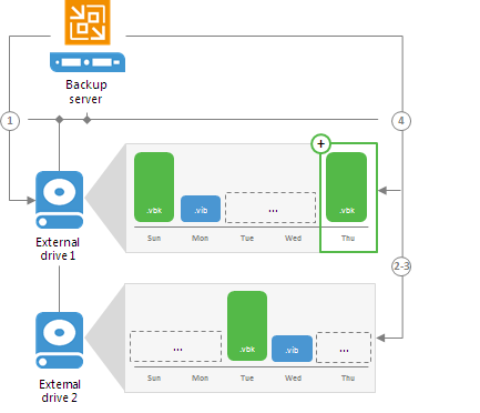
- [For backup jobs] Veeam Backup & Replication checks the backup chain for consistency and creates a new full backup.
- [For backup copy jobs] If the attached drive is empty, Veeam Backup & Replication creates a full backup on it. If there is a backup chain on the drive, Veeam Backup & Replication creates a new incremental backup and adds it to the backup chain. The latest incremental backup existing in the backup chain is used as a starting point for the new incremental backup.
When you specify retention settings for a job targeted at a backup repository with rotated drives, you must define the total number of restore points that you want to retain on all drives in the set. For example, if you set retention to 14, the job will keep the total of 14 restore points across all drives.
![Backup Repositories with Rotated Drives]()
Drive letters for external drives may change when you add new volumes or storage hardware such as CD-ROM on the server. On Microsoft Windows backup repositories, Veeam Backup & Replication can keep track of drives and detect them even if the drive letter changes.
To detect a drive correctly, Veeam Backup & Replication must have a record about it in the configuration database. Consider the following requirements:
- When you insert a drive for the first time, the drive is not registered in the configuration database. Such drive must have the same letter as the one specified in the Path to folder field in the backup repository settings.
If the drive has some other letter, Veeam Backup & Replication will not be able to detect and use it.
- When you insert a drive that has already been used and has some restore points on it, the drive is already registered in the configuration database. Veeam Backup & Replication will be able to detect and use it, even if the drive letter changes.
Linux and Shared Folder Backup Repository
If you use a Linux server or CIFS share as a backup repository with rotated drives, Veeam Backup & Replication employs a “cropped” mechanism of work with rotated drives.
Veeam Backup & Replication keeps information only about the latest backup chain in the configuration database. Information about previous backup chains is removed from the database. For this reason, the retention policy set for the job may not work as expected.
A job targeted at a backup repository with rotated drives is performed in the following way:
- During the first run of the job, Veeam Backup & Replication creates a regular backup full backup on the drive that is attached to the backup repository server.
- During the next job session, Veeam Backup & Replication checks if the current backup chain on the attached drive is consistent. The consistent backup chain must contain a full backup and all incremental backups subsequent to it. This requirement applies to all types of backup chains: forever forward incremental, forward incremental and reverse incremental.
- If the current backup chain is consistent, Veeam Backup & Replication adds a new restore point to the backup chain.
- If external drives have been swapped, and the current backup chain is not consistent,
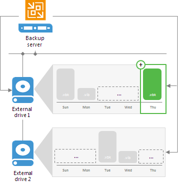
- Veeam Backup & Replication always starts a new backup chain (even if restore points from previous backup chains are available on the attached drive). Veeam Backup & Replication creates a new full backup file on the drive, and this full backup is used as a starting point for subsequent incremental backups.
As soon as Veeam Backup & Replication starts a new backup chain on the drive, it removes information about restore points from previous backup chains from the configuration database. Backup files corresponding to these previous restore points are not deleted, they remain on disk. This happens because Veeam Backup & Replication applies the retention policy only to the current backup chain, not to previous backup chains.
![Backup Repositories with Rotated Drives]()
Limitations for Backup Repositories with Rotated Drives
Backup repositories with rotated drives have the following limitations:
- You cannot store archive full backups (GFS backups) created with backup copy jobs in backup repositories with rotated drives.
- You cannot store per-VM backup files in backup repositories with rotated drives.
Support for Deduplicating Storage Systems
For disk-to-disk backups, you can use a deduplicating storage system as a target.
Veeam Backup & Replication supports the following deduplicating storage appliances:
- EMC Data Domain
- ExaGrid
- HPE StoreOnce
EMC Data Domain
You can use EMC Data Domain storage systems with Data Domain Boost (DD Boost) as backup repositories.
The DD Boost technology offers a set of features for advanced data processing:
- Distributed Segment Processing
- Advanced Load Balancing and Link Failover
- Virtual Synthetics
- Managed File Replication
Veeam Backup & Replication supports Distributed Segment Processing, Advanced Load Balancing, Link Failover and Virtual Synthetics. Managed File Replication is not supported.
In addition to these technologies, Veeam Backup & Replication supports in-flight data encryption and per storage unit streams.
Distributed Segment Processing
Distributed Segment Processing lets EMC Data Domain “distribute” the deduplication process and perform a part of data deduplication operations on the backup proxy side.
Without Distributed Segment Processing, EMC Data Domain performs deduplication on the EMC Data Domain storage system. The backup proxy sends unfiltered data blocks to EMC Data Domain over the network. Data segmentation, filtering and compression operations are performed on the target side, before data is written to disk.
With Distributed Segment Processing, operations on data segmentation, filtering and compression are performed on the backup proxy side. The backup proxy sends only unique data blocks to EMC Data Domain. As a result, the load on the network reduces and the network throughput improves.
Advanced Load Balancing and Link Failover
Advanced Load Balancing and Link Failover allow you to balance data transfer load and route VM data traffic to a working link in case of network outage problems.
Without Advanced Load Balancing, every backup server connects to Data Domain on a dedicated Ethernet link. Such configuration does not provide an ability to balance the data transfer load across the links. If a network error occurs during the data transfer process, the backup job fails and needs to be restarted.
Advanced Load Balancing allows you to aggregate several Ethernet links into one interface group. As a result, EMC Data Domain automatically balances the traffic load coming from several backup servers united in one group. If some link in the group goes down, EMC Data Domain automatically performs link failover, and the backup traffic is routed to a working link.
Virtual Synthetics
Veeam Backup & Replication supports Virtual Synthetic Fulls by EMC Data Domain. Virtual Synthetic Fulls let you synthesize a full backup on the target backup storage without physically copying data from source volumes. To construct a full backup file, EMC Data Domain uses pointers to existing data segments on the target backup storage. Virtual Synthetic Fulls reduce the workload on the network and backup infrastructure components and increase the backup job performance.
In-Flight Data Encryption
Veeam Backup & Replication supports in-flight encryption introduced in EMC Data Domain Boost 3.0. If necessary, you can enable data encryption at the backup repository level. Veeam Backup & Replication will leverage the EMC Data Domain technology to encrypt data transported between the EMC DD Boost library and EMC Data Domain system.
Per Storage Unit Streams
Veeam Backup & Replication supports per storage unit streams on EMC Data Domain. The maximum number of parallel tasks that can be targeted at the backup repository (the
Limit maximum concurrent tasks to N setting) is applied to the storage unit, not the whole EMC Data Domain system.
How EMC Data Domain Works
To support the EMC DD Boost technology, Veeam Backup & Replication leverages two EMC Data Domain components:
- DD Boost library. The DD Boost library is a component of the EMC Data Domain system. The DD Boost library is embedded into the Veeam Data Mover Service setup. When you add a Microsoft Windows server to the backup infrastructure, the DD Boost Library is automatically installed on the added server together with the Data Mover Service.
- DD Boost server. The DD Boost server is a target-side component running on the OS of the EMC Data Domain storage system.
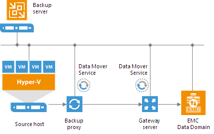
To communicate with EMC Data Domain, Veeam Backup & Replication uses the DD Boost library deployed on a gateway server. The gateway server is a backup infrastructure component that “bridges” the backup server and EMC Data Domain storage system. The gateway server must meet the following requirements:
- The server must run Microsoft Windows OS.
- The server must be added to the backup infrastructure.
- The server must have access to the backup server and EMC Data Domain appliance.
You define what gateway server to use when you assign a backup repository role to EMC Data Domain. You can define the gateway server explicitly or instruct Veeam Backup & Replication to select it automatically.
For EMC Data Domain storage systems working over Fibre Channel, you must explicitly define the gateway server that will communicate with EMC Data Domain. As a gateway server, you must use a Microsoft Windows server that is added to the backup infrastructure and has access to EMC Data Domain over Fibre Channel.
![How EMC Data Domain Works]()
Supported Protocols
Veeam Backup & Replication supports EMC Data Domain storage systems working over the following protocols:
- TCP/IP protocol: Veeam Backup & Replication communicates with the EMC Data Domain server by sending commands over the network.
- Fibre Channel protocol: Veeam Backup & Replication communicates with the EMC Data Domain Fibre Channel server by sending SCSI commands over Fibre Channel.
Limitations for EMC Data Domain
If you plan to use EMC Data Domain as a backup repository, mind the following limitations:
- Use of EMC Data Domain with DD Boost does not guarantee improvement of job performance; it reduces the load on the network and improves the network throughput.
- EMC Data Domain requires at least 1 Gbps network and 0% of packets data loss between the gateway server and EMC Data Domain storage appliance. In the opposite case, stable work of EMC Data Domain cannot be guaranteed.
- EMC Data Domain does not support the reverse incremental backup method. Do not enable this option for backup jobs targeted at this type of backup repository.
- When you create a backup job targeted at EMC Data Domain, Veeam Backup & Replication will offer you to switch to optimized job settings and use the 4 MB size of data block for VM data processing. It is recommended that you use optimized job settings. Large data blocks produce a smaller metadata table that requires less memory and CPU resources to process.
- The length of forward incremental and forever forward incremental backup chains (chains that contain one full backup and a set of subsequent incremental backups) cannot be greater than 60 restore points. To overcome this limitation, schedule full backups (active or synthetic) to split the backup chain into shorter series. For example, to perform backups at 30-minute intervals 24 hours a day, you must schedule synthetic fulls every day. In this scenario, intervals immediately after midnight may be skipped due to duration of synthetic processing.
- If you connect to EMC Data Domain over Fibre Channel, you must explicitly define a gateway server to communicate with EMC Data Domain. As a gateway server, you must use a Microsoft Windows server that is added to the backup infrastructure and has access to the EMC Data Domain storage appliance over Fibre Channel.
ExaGrid
You can use ExaGrid appliances as backup repositories.
ExaGrid uses post-process deduplication. Data deduplication is performed on the target storage system. After VM data is written to disk, ExaGrid analyses bytes in the newly transferred data portions. ExaGrid compares versions of data over time and stores only the differences to disk.
ExaGrid deduplicates data at the storage level. Identical data blocks are detected throughout the whole storage system, which increases the deduplication ratio.
Veeam Backup & Replication works with ExaGrid appliances as with a Linux backup repository. To communicate with ExaGrid, Veeam Backup & Replication uses two Data Mover Services that are responsible for data processing and transfer:
- Data Mover Service on the backup proxy
- Data Mover Service on the ExaGrid appliance
Limitations for ExaGrid
ExaGrid appliances achieve a lower deduplication ratio when a backup job uses multi-task processing. Processing a single task at a time within each backup job results in the best deduplication ratio. If you decide to use ExaGrid as a backup repository, all tasks executed within a backup job should be processed sequentially, one by one. To do this, you must limit the maximum concurrent tasks to 1 in the settings of ExaGrid backup repositories.
The ExaGrid appliance can handle many concurrent backup jobs, with one of the highest ingest rates in the market. To accomplish the maximum ingest and shortest backup time, you need to configure multiple backup jobs, each targeted at its own backup repository. Then schedule these jobs to run concurrently.
HPE StoreOnce
You can use HPE StoreOnce storage appliances as backup repositories. Depending on the storage configuration and type of the backup target, HPE StoreOnce can work in the following ways:
- Perform source-side deduplication
- Perform target-side deduplication
- Work in the shared folder mode
Source-Side Data Deduplication
HPE StoreOnce performs source-side deduplication if the backup target meets the following requirements:
- You have a Catalyst license installed on HPE StoreOnce.
- You use a Catalyst store as a backup repository.
- The Catalyst store is configured to work in the Low Bandwidth mode (Primary and Secondary Transfer Policy).
- You add the HPE StoreOnce Catalyst as a deduplicating storage appliance, not as a shared folder to the backup infrastructure.
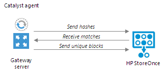
To deduplicate data on the source side, HPE StoreOnce uses the HPE StoreOnce Catalyst agent.
The HPE StoreOnce Catalyst
agent is a component of the HPE StoreOnce Catalyst software. It is installed on the gateway server communicating with the HPE StoreOnce appliance.
HPE StoreOnce deduplicates data on the source side, before writing it to target:
- During the backup job session, HPE StoreOnce analyzes data incoming to the HPE StoreOnce appliance in chunks and computes a hash value for every data chunk. Hash values are stored in an index on disk.
- The HPE StoreOnce Catalyst agent calculates hash values for data chunks in a new data flow and sends these hash values to target.
- HPE StoreOnce identifies which data blocks are already saved on disk and communicates this information to the HPE StoreOnce Catalyst agent. The HPE StoreOnce Catalyst agent sends only unique data blocks to target.
As a result, the load on the network reduces, the backup job performance improves, and you can save on disk space.
![HPE StoreOnce]()
Target-Side Data Deduplication
HPE StoreOnce performs target-side deduplication if the backup target is configured in the following way:
- The Catalyst store works in the High Bandwidth mode (Primary or Secondary Transfer Policy is set to High Bandwidth).
- The Catalyst license is installed on the HPE StoreOnce (required).
- The Catalyst store is added as a backup repository to the backup infrastructure.
- The Catalyst license is not required.
- The CIFS store is added as a backup repository to the backup infrastructure.
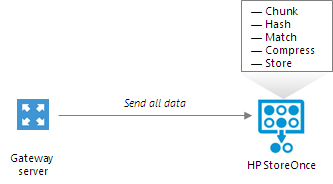
HPE StoreOnce deduplicates data on the target side, after the data is transported to HPE StoreOnce:
- HPE StoreOnce analyzes data incoming to the HPE StoreOnce appliance in chunks and creates a hash value for every data chunk. Hash values are stored in an index on the target side.
- HPE StoreOnce analyzes VM data transported to target and replaces identical data chunks with references to data chunks that are already saved on disk.
As a result, only new data chunks are written to disk, which helps save on disk space.
![HPE StoreOnce]()
Shared Folder Mode
If you do not have an HPE StoreOnce Catalyst license, you can add the HPE StoreOnce appliance as a shared folder backup repository. In this mode, HPE StoreOnce will perform target-side deduplication.
If you work with HPE StoreOnce in the shared folder mode, the performance of backup jobs and transform operations is lower (in comparison with the integration mode, when HPE StoreOnce is added as a deduplicating storage appliance).
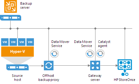
How HPE StoreOnce Works
To work with HP StoreOnce, Veeam Backup & Replication leverages the HPE StoreOnce Catalyst technology and two HPE StoreOnce components:
- HPE StoreOnce Catalyst agent. The HPE StoreOnce Catalyst agent is a component of the HPE StoreOnce Catalyst software. The HPE StoreOnce Catalyst agent is embedded into the Veeam Data Mover Service setup. When you add a Microsoft Windows server to the backup infrastructure, the HPE StoreOnce Catalyst agent is automatically installed on the added server together with the Data Mover Service.
- HPE StoreOnce appliance. The HPE StoreOnce appliance is an HPE StoreOnce storage system on which Catalyst stores are created.
Veeam Backup & Replication uses two Data Mover Services:
- Data Mover Service on the backup proxy
- Data Mover Service on the gateway server
The gateway server is a backup infrastructure component that “bridges” the backup server and HPE StoreOnce appliance. The gateway server must meet the following requirements:
- The server must run Microsoft Windows OS.
- The server must be added to the backup infrastructure.
- The server must have access to the backup server and HPE StoreOnce appliance.
The gateway server is selected when you assign a backup repository role to the HPE StoreOnce appliance. You can define the gateway server explicitly or instruct Veeam Backup & Replication to select it automatically.
For HPE StoreOnce storage systems working over Fibre Channel, you must explicitly define the gateway server to communicate with HPE StoreOnce. As a gateway server, you must use a Microsoft Windows server that is added to the backup infrastructure and has access to HPE StoreOnce over Fibre Channel.
![How HPE StoreOnce Works]() Tip: Tip: |
For work with HP StoreOnce, Veeam Backup & Replication uses the Catalyst agent installed on the gateway proxy. If you want to reduce the load on the network between the source and target side, assign the gateway server role to a machine on the source side, closer to the backup proxy.
|
![How HPE StoreOnce Works]()
Limitations for HPE StoreOnce
If you plan to use HPE StoreOnce as a backup repository, mind the following limitations. Limitations apply only if you use HPE StoreOnce in the integration mode, not the shared folder mode.
- Backup files on HPE StoreOnce are locked exclusively by a job or task. If you start several tasks at a time, Veeam Backup & Replication will perform a task with a higher priority and will skip or terminate a task with a lower priority.
In Veeam Backup & Replication, tasks have the following priority levels (starting with the top priority): backup job > backup copy > restore. For example, if the backup and backup copy jobs start simultaneously, Veeam Backup & Replication will terminate the backup copy task. If a file is locked with the backup job, you will not be able to restore VM data from this file.
- When you create a backup job targeted at HPE StoreOnce, Veeam Backup & Replication will offer you to switch to optimized job settings and use the 4 MB size of data block for VM data processing. It is recommended that you use optimized job settings. Large data blocks produce a smaller metadata table that requires less memory and CPU resources to process.
- The HPE StoreOnce backup repository always works in the Use per-VM backup files mode.
- The length of backup chains (chains that contain one full backup and a set of subsequent incremental backups) on HPE StoreOnce cannot be greater than 7 restore points. The recommended backup job schedule is the following: not more than 1 incremental backup once a day, not fewer than one full backup (active or synthetic) once a week.
- HPE StoreOnce does not support the reverse incremental backup method.
- The HPE StoreOnce backup repository does not support the Defragment and compact full backup file option (for backup and backup copy jobs).
- You cannot perfom quick migration for Microsoft Hyper-V VMs started with Instant VM Recovery from the backup that resides on the HP StoreOnce backup repository.
- You cannot use the HP StoreOnce backup repository as a target for Veeam Endpoint backup jobs. Backup copy jobs, however, can be targeted at the HP StoreOnce backup repository.
- You cannot use the HPE StoreOnce backup repository as a source or target for file copy jobs.
- You cannot use the HPE StoreOnce backup repository as a cloud repository.
Several Backup Repositories on HPE StoreOnce
You can configure several backup repositories on one HPE StoreOnce appliance and associate them with different gateway servers.
Mind the following:
- If you configure several backup repositories on HPE StoreOnce and add them as extents to a scale-out backup repository, make sure that all backup files from one backup chain are stored on one extent. If backup files from one backup chain are stored to different extents, the transform operations performance will be lower.
- HPE StoreOnce has a limit on the number of opened files that applies to the whole appliance. Tasks targeted at different backup repositories on HPE StoreOnce and run in parallel will equally share this limit.
- For HPE StoreOnce working over Fibre Channel, there is a limitation on the number of connections from one host. If you connect several backup repositories to one gateway, backup repositories will compete for connections.
- Deduplication on HPE StoreOnce works within the limits of one object store.
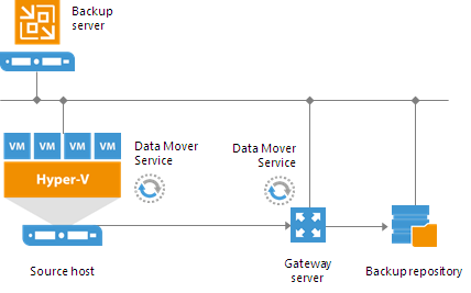
Gateway Server
A gateway server is an auxiliary backup infrastructure component that “bridges” the backup server and backup repository. The gateway server is required if you deploy the following types of backup repositories in the backup infrastructure:
- Shared folder backup repositories
- EMC DataDomain and HPE StoreOnce deduplicating storage appliances
Shared folder repositories, EMC DataDomain and HPE StoreOnce cannot host Data Mover Services — Veeam components that establish a connection between a backup proxy and backup repository (in case of backup jobs) or between backup repositories (in case of backup copy jobs). To overcome this limitation, Veeam Backup & Replication uses gateway servers.
In the backup infrastructure, a gateway server hosts the Veeam Data Mover Service.
Veeam Backup & Replication establishes a connection between the source Data Mover Service and target Data Mover Service, and transports data from/to backup repositories via gateway servers.
![Gateway Server]()
A machine performing the role of a gateway server must meet the following requirements:
- A gateway server can run on a physical or virtual machine.
- The gateway server can run on a Microsoft Windows machine or Microsoft Hyper-V host.
- The machine must be added to the backup infrastructure.
- The machine must have access to the backup repository — shared folder, EMC DataDomain or HPE StoreOnce.
To configure a gateway server, you must pass through the
Add New Backup Repository wizard and select a machine that will perform the role of a gateway server. You can select a gateway server explicitly or instruct Veeam Backup & Replication to select it automatically.
- If you select a gateway server explicitly, Veeam Backup & Replication uses the selected machine as a gateway server.
- If you instruct Veeam Backup & Replication to select the gateway server automatically, Veeam Backup & Replication selects a gateway server using the following rules:
- For backup jobs: the role of a gateway server is assigned to a machine performing the role of a backup proxy (onsite or offsite).
- For backup copy jobs: if a backup copy job uses a direct data path, the role of a gateway server is assigned to the mount server associated with the backup repository (Veeam Backup & Replication fails over to the backup server if the mount server is not accessible for some reason). If a backup copy job uses WAN accelerators, the role of a gateway server is assigned to WAN accelerators. For example, if you copy backup from a source Microsoft Windows backup repository to a shared folder backup repository, the gateway server role is assigned to the target WAN accelerator. If you copy backups between 2 shared folder backup repositories, the gateway server role is assigned to the source and target WAN accelerators.
- For backup to tape jobs: the role of a gateway server is assigned to the backup server.
In the common case, a machine to which you assign the role of a gateway server must be located as close to the backup repository as possible. However, if you use a deduplicating storage appliance with source-side data deduplication, it is reasonable to assign the role of a gateway server to a machine that is located closer to the backup proxy. This will help you reduce the amount of traffic travelling over the network.
Veeam Backup & Replication may use one or several gateway servers to process VMs in the job. The number of gateway servers depends on backup repository settings. If the
Use per-VM backup files option is disabled, Veeam Backup & Replication selects one gateway server for the whole backup repository. If the
Use per-VM backup files option is enabled, Veeam Backup & Replication selects a gateway server per every VM in the job. The rules of gateway server selection are described above.
For example, a backup job processes 2 VMs. The job is targeted at a backup repository for which the
Use per-VM backup files option is enabled. In this case, Veeam Backup & Replication will detect which backup proxies were used to process VMs in the job. If VMs were processed with 2 different backup proxies, Veeam Backup & Replication will assign the role of gateway servers to these backup proxies. If VMs were processed with the same backup proxy, Veeam Backup & Replication will assign the role of a gateway server to this backup proxy, and will use it for both VMs in the job.
For scale-out backup repositories, Veeam Backup & Replication uses one gateway server per every extent. The rules of gateway server selection are described above.
Limitations for Gateway Servers
For deduplicating storage appliances working over Fibre Channel, you must explicitly select a gateway server that will communicate with the appliance. As a gateway server, you must use a Microsoft Windows server that is added to the backup infrastructure and has access to the appliance over Fibre Channel.
Mount Server
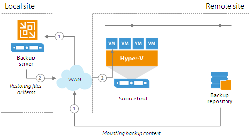
The mount server is required if you perform restore VM guest OS files and application items to the original location. The mount server lets you route VM traffic by an optimal way, reduce load on the network and speed up the restore process.
When you perform file-level restore or application item restore, Veeam Backup & Replication needs to mount the content of the backup file to a staging server. The staging server must be located in the same site as the backup repository where backup files are stored. If the staging server is located in some other site, Veeam Backup & Replication may route data traffic in a non-optimal way.
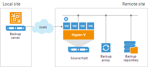
For example, if the backup server is located in the local site while the source host and backup repository are located in the remote site, during restore to original location Veeam Backup & Replication will route data traffic in the following way:
- From the remote site to the local site — to mount the content of the backup file to the staging server.
- From the local site to the remote site — to restore files or application items.
![Mount Server]()
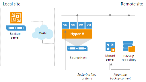
To prevent VM data from traveling between sites, Veeam Backup & Replication uses the mount server. The mount server acts as a "mount point" for backups in the backup repository. When you restore files or application items to the original location, Veeam Backup & Replication mounts the content of the backup file to the mount server (or the original VM for restore to the Microsoft SQL Server and Oracle VMs) and copies files or items to their destination via this mount server or VM.
The mount server is created for every backup repository and associated with it. When you configure a backup repository, you define which server you want to use as a mount server for this backup repository. By default, Veeam Backup & Replication assigns the mount server role to the following machines:
- Backup repository. For Microsoft Windows backup repositories, the mount server role is assigned to the backup repository server itself.
- Backup server. For Linux, shared folder backup repositories and deduplicating storage appliances, the mount server role is assigned to the backup server.
- Veeam Backup & Replication console. The mount server role is also assigned to a machine on which the Veeam Backup & Replication console is installed. Note that this type of mount server is not registered in the Veeam Backup & Replication configuration database.
For scale-out backup repositories, you must define the mount server for every extent.
If you do not want to use default mount servers, you can assign the mount server role to any Microsoft Windows machine in the backup infrastructure. It is recommended that you configure at least one mount server in each site and associate this mount server with the backup repository residing in this site. The mount server and backup repository must be located as close to each other as possible. In this case, you will be able to keep the VM traffic in one site.
![Mount Server]()
Services and Components
On the mount server machine, Veeam Backup & Replication installs the Veeam Mount Service. The Veeam Mount Service requires .NET 4.5.2. If .NET 4.5.2 is not installed on the machine, Veeam Backup & Replication will install it automatically.
Requirements to Mount Server
The machine to which you assign the mount server role must meet the following requirements:
- You can assign the role of a mount server to Microsoft Windows machines (physical or virtual).
- You can assign the role of a mount server to 64-bit machines only.
- The mount server must have access to the backup repository with which it is associated and to the original VM (VM to which you restore files or application items). For restore from storage snapshots, the mount server must also have access to the ESX(i) host on which the temporary VM is registered.
Veeam Backup Enterprise Manager
Veeam Backup Enterprise Manager is an optional component intended for distributed enterprise environments with multiple backup servers. Veeam Backup Enterprise Manager federates backup servers and offers a consolidated view of these servers through a web browser interface. You can centrally control and manage all jobs through a single "pane of glass", edit and clone jobs, monitor job state and get reporting data across all backup servers. Veeam Backup Enterprise Manager also enables you to search for VM guest OS files in all current and archived backups across your backup infrastructure, and restore these files in one click.
Veeam Backup Enterprise Manager can be installed on a physical or virtual machine. You can deploy it on the backup server or use a dedicated machine.
Veeam Backup Enterprise Manager uses the following services and components:
- Veeam Backup Enterprise ManagerService coordinates all operations of Veeam Backup Enterprise Manager, aggregates data from multiple backup servers and provides control over these servers.
- Veeam Backup Enterprise Manager Configuration Database is used by Veeam Backup Enterprise Manager for storing data. The database instance can be located on a SQL Server installed either locally (on the same machine as Veeam Backup Enterprise Manager Server) or remotely.
- Veeam Guest Catalog Service replicates and consolidates VM guest OS file system indexing data from backup servers added to Veeam Backup Enterprise Manager. Index data is stored in Veeam Backup Enterprise Manager Catalog (a folder on the Veeam Backup Enterprise Manager Server) and is used to search for VM guest OS files in backups created by Veeam Backup & Replication.
Veeam Backup Search
By default, Veeam Backup & Replication uses its proprietary file indexing mechanism to index VM guest OS files and let you search for them in backups with Veeam Backup Enterprise Manager. Using Veeam's proprietary mechanism is the best practice. However, you have an option to engage the Veeam Backup Search component and Microsoft Search Server in the indexing process.
To use Veeam Backup Search, you should install the Veeam Backup Search component from the installation package on a machine running Microsoft Search Server. The Veeam Backup Search server runs the
MOSS Integration Service that invokes updates of index databases on Microsoft Search Server. The service also sends search queries to Microsoft Search Server which processes them and returns necessary search results to
Veeam Backup Enterprise Manager.
Deployment Scenarios
Veeam Backup & Replication can be used in virtual environments of any size and complexity. The architecture of the solution supports onsite and offsite data protection, operations across remote sites and geographically dispersed locations. Veeam Backup & Replication provides flexible scalability and easily adapts to the needs of your virtual environment.
Before installing Veeam Backup & Replication, familiarize yourself with common deployment scenarios and carefully plan your backup infrastructure layout.
In This Section
- Simple Deployment
- Advanced Deployment
- Distributed Deployment
Simple Deployment
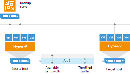
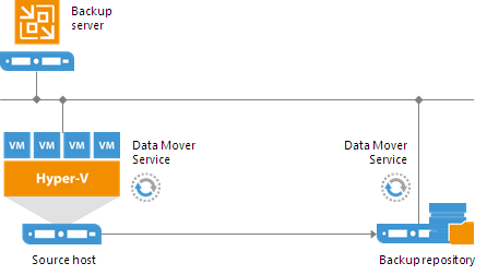
In a simple deployment scenario, one instance of Veeam Backup & Replication is installed on a physical or virtual Windows-based machine. This installation is referred to as a backup server.
Simple deployment implies that the backup server performs the following:
- It functions as a management point, coordinates all jobs, controls their scheduling and performs other administrative activities.
- It is used as the default backup repository. During installation, Veeam Backup & Replication checks volumes of the machine on which you install the product and identifies a volume with the greatest amount of free disk space. On this volume, Veeam Backup & Replication creates the Backup folder that is used as the default backup repository.
- It is used as a mount server and guest interaction proxy.
In this scenario, source Hyper-V servers act as backup proxies, handling job processing and transferring backup traffic directly to the target. All necessary backup proxy services are installed on source Hyper-V servers.
![Simple Deployment]()
If you plan to back up and replicate only a small number of VMs or evaluate Veeam Backup & Replication, this configuration is enough to get you started. Veeam Backup & Replication is ready for use right out of the box — as soon as it is installed, you can start using the solution to perform backup and replication operations. To balance the load of backing up and replicating your VMs, you can schedule jobs at different times.
![Simple Deployment]() Tip: Tip: |
If you decide to use a simple deployment scenario, you can install Veeam Backup & Replication right on the Hyper-V host where VMs you want to work with reside. However, to use this Hyper-V host as the source for backup and replication, you will still need to add it to the Veeam Backup & Replication console. |
In Hyper-V environments that require a large number of backup or replication activities performed, the simple deployment scheme is not appropriate due to the following reasons:
- The backup server might not have enough disk capacity to store the required amount of backup data.
- A significant load is placed on production servers that combine the roles of backup proxies and source hosts.
To take the overhead off the backup server and source Hyper-V servers, you can use the advanced deployment scenario.
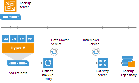
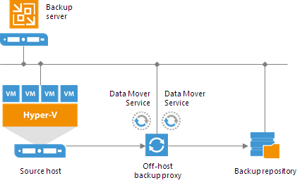
Advanced Deployment
For mid-size and large-scale Hyper-V environments with a great number of backup and replication jobs, the advanced deployment scenario can be a good choice.
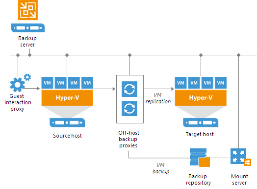
The advanced deployment includes the following components:
- Virtual infrastructure servers — Hyper-V hosts used as source and target for backup and replication.
- Backups server — a configuration and control center of the backup infrastructure.
- Off-host backup proxy — a “data mover” component used to retrieve VM data from the source datastore, process it and deliver to the target.
- Backup repository — a location used to store backup files and auxiliary replica files.
- Dedicated mount servers — component required for VM guest OS files and application items restore to the original location.
- Dedicated guest interaction proxies — components used to deploy the runtime process in Microsoft Windows VMs.
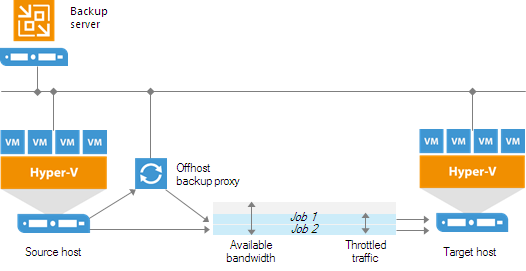
In the advanced deployment scenario, data processing is shifted from the Hyper-V server to an off-host backup proxy — a dedicated machine that is deployed on the source side, closer to the source Hyper-V host. The off-host backup proxy functions as a “data mover”, processing VM data and mediating the backup traffic from source to target. Therefore, the job processing overhead and data transport is offloaded from the source Hyper-V host.
In the advanced deployment scenario, backup data is no longer stored to the backup repository on the backup server. Instead, data is transported to dedicated backup repositories. The backup server becomes a “manager” for off-host backup proxies and backup repositories.
![Advanced Deployment]()
With the advanced deployment scenario, you can expand your backup infrastructure horizontally in a matter of minutes to meet your data protection requirements. Instead of growing the number of backup servers or constantly tuning job scheduling, you can install multiple backup infrastructure components and distribute the backup workload among them. The installation process is fully automated, which simplifies deployment and maintenance of the backup infrastructure in your virtual environment.
In virtual environments with several proxies, Veeam Backup & Replication dynamically distributes the backup traffic among these proxies. A job can be explicitly mapped to a specific proxy. Alternatively, you can let Veeam Backup & Replication choose an off-host backup proxy.
In this case, Veeam Backup & Replication will check settings of available backup proxies and select the most appropriate one for the job. The backup proxy should have access to the source and target hosts, and to backup repositories to which files will be written.
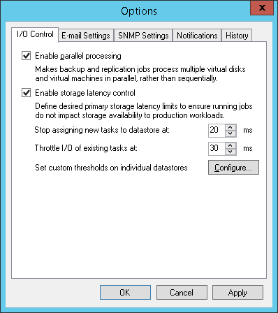
To regulate the backup load, you can specify the maximum number of concurrent tasks per backup proxy and set up throttling rules to limit the proxy bandwidth. For a backup repository, you can set the maximum number of concurrent tasks and define a combined data rate.
Distributed Deployment
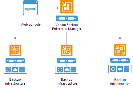
The distributed deployment scenario is recommended for large geographically dispersed virtual environments with multiple backup servers installed across different sites. These backup servers are federated under Veeam Backup Enterprise Manager — an optional component that provides centralized management and reporting for these servers through a web interface.
![Distributed Deployment]()
Veeam Backup Enterprise Manager collects data from backup servers and enables you to run backup and replication jobs across the entire backup infrastructure through a single "pane of glass", edit them and clone jobs using a single job as a template. It also provides reporting data for various areas (for example, all jobs performed within the last 24 hours or 7 days, all VMs engaged in these jobs and so on).
Using indexing data consolidated on one server, Veeam Backup Enterprise Manager provides advanced capabilities to search for VM guest OS files in VM backups created on all backup servers (even if they are stored in repositories on different sites), and recover them in a single click. Search for VM guest OS files is enabled through Veeam Backup Enterprise Manager itself; to streamline the search process, you can optionally deploy a Veeam Backup Search server in your backup infrastructure.
With flexible delegation options and security roles, IT administrators can delegate the necessary file restore or VM restore rights to authorized personnel in the organization – for example, allow database administrators to restore Oracle or SQL server VMs.
If you use Veeam Backup Enterprise Manager in your backup infrastructure, you do not need to install licenses on every backup server you deploy. Instead, you can install one license on the Veeam Backup Enterprise Manager server and it will be applied to all servers across your backup infrastructure. This approach simplifies tracking license usage and license updates across multiple backup servers.
Resource Scheduling
With its built-in mechanism of resource scheduling, Veeam Backup & Replication is capable to automatically select and use optimal resources to run configured jobs. Resource scheduling is performed by the Veeam Backup Service running on the backup server. When a job starts, it communicates with the service to inform it about the resources it needs. The service analyzes job settings, parameters specified for backup infrastructure components, current load on the components, and automatically allocates optimal resources to the job.
For resource scheduling, Veeam Backup Service uses a number of settings and features:
In This Section
- Network Traffic Throttling and Multithreaded Data Transfer
- Limiting the Number of Concurrent Tasks
- Limiting Read and Write Data Rates for Backup Repositories
- Detecting Performance Bottlenecks
- Data Processing Modes
Network Traffic Throttling and Multithreaded Data Transfer
To limit the impact of Veeam Backup & Replication tasks on network performance, you can throttle network traffic for jobs. Network traffic throttling prevents jobs from utilizing the entire bandwidth available in your environment and makes sure that enough traffic is provided for other network operations. It is especially recommended that you throttle network traffic if you perform offsite backup or replicate VMs to a DR site over slow WAN links.
Network traffic throttling is implemented through rules. Network throttling rules apply to components in the Veeam backup infrastructure, so you do not have to make any changes to the network infrastructure.
Network traffic throttling rules are enforced globally, at the level of the backup server. Every rule limits the maximum throughput of traffic going between backup infrastructure components on which Veeam Data Mover Services are deployed. Depending on the scenario, traffic can be throttled between the following components:
- Backup to a Microsoft Windows or Linux backup repository: a backup proxy (onhost or offhost) and backup repository
- Backup to an SMB share, EMC Data Domain and HPE StoreOnce: backup proxy (onhost or offhost) and gateway server
- Backup copy: source and target backup repositories or gateway sever(s), or WAN accelerators (if WAN accelerators are engaged in the backup copy process)
- Replication: source and target backup proxies (onhost or offhost) or WAN accelerators (if WAN accelerators are engaged in the replication process)
- Backup to tape: backup repository and tape server
Rules are set for a pair of IP address ranges and are applied to the source and target components between which data is transferred over the network. The range can include a single IP address.
When a new job starts, Veeam Backup & Replication checks network traffic throttling rules against a pair of components assigned for the job. If the source and target IP addresses fall into specified IP ranges, the rule is applied. For example, if for a network traffic throttling rule you specify 192.168.0.1 – 192.168.0.255 as the source range and 172.16.0.1 – 172.16.0.255 as the target range, and the source component has IP address 192.168.0.12, while the target component has IP address 172.16.0.31, the rule will be applied. The network traffic going from source to target will be throttled.
![Network Traffic Throttling and Multithreaded Data Transfer]()
![Network Traffic Throttling and Multithreaded Data Transfer]() Note: Note: |
Throttling rules are reversible — they function in two directions. If the IP address of the component on the source side falls into the target IP range, and the IP address of the component on the target side falls into the source IP range, the rule will be applied in any case.
|
Veeam Backup & Replication equally splits available bandwidth between all jobs that use backup infrastructure components to which a network throttling rule applies. For example, if you run one job that uses a pair of backup infrastructure components to which the rule applies, the job will get the entire bandwidth allowed by the rule. If you run two jobs at a time, the allowed bandwidth will be equally split between them. As soon as one of the jobs completes, the bandwidth assigned to it will be freed, and the remaining job will use the entire bandwidth allowed by the rule.
![Network Traffic Throttling and Multithreaded Data Transfer]()
Throttling rules can be scheduled to only be active during specific time intervals (for example, during business hours). This way, you can minimize the impact of job performance spikes on the production network. Alternatively, you can select to apply throttling rules regardless of the time.
Multithreaded Data Transfer
In addition to traffic throttling, Veeam Backup & Replication offers another possibility for network traffic management — management of data transfer connections. Normally, within one backup session Veeam Backup & Replication opens five parallel TCP/IP connections to transfer data from source to target. Multithreaded data transfer increases the transfer speed but can place additional load on the network.
If required, you can disable multithreaded data transfer and limit the number of connections per session to one.
![Network Traffic Throttling and Multithreaded Data Transfer]() Note: Note: |
Veeam Backup & Replication performs a CRC check for the TCP traffic going between the source and the target. When you perform backup and replication operations, Veeam Backup & Replication calculates checksums for data blocks going from the source. On the target, it re-calculates checksums for received data blocks and compares them to the checksums created on the source. If the CRC check fails, Veeam Backup & Replication automatically re-sends data blocks without any impact on the job. |
Limiting the Number of Concurrent Tasks
To avoid overload of backup proxies and backup repositories, Veeam Backup & Replication allows you to limit the number of concurrent tasks performed on a backup proxy (either on-host or off-host) or targeted at a backup repository.
Before processing a new task, Veeam Backup & Replication detects what backup infrastructure components (backup proxies and repositories) will be involved. When a new job starts, Veeam Backup & Replication analyzes the list of VMs that the job includes, and creates a separate task for each disk of every VM to be processed. Tasks in the job can be processed in parallel (that is, VMs and VM disks within a single job can be processed simultaneously), optimizing your backup infrastructure performance and increasing the efficiency of resource usage.
![Limiting the Number of Concurrent Tasks]() Note: Note: |
To use this capability, proxy server(s) should meet system requirements – each task requires a single CPU core, so for two tasks to be processed in parallel, 2 cores is the recommended minimum. Parallel VM processing must also be enabled in Veeam Backup & Replication options.
|
Task limiting is performed by the Veeam Backup Service that is aware of all backup proxies and backup repositories connected to it, and settings specified for these backup proxies and repositories (namely, the number of allowed concurrent tasks).
When a job starts, it informs the Veeam Backup Service about its task list and polls the service about allocated resources to its tasks at a 10 second interval after that. Before a new task targeted at a specific backup proxy or repository starts, the Veeam Backup Service checks the current workload (the number of tasks currently working with the proxy or repository) and the number of allowed tasks per this component. If this number is exceeded, a new task will not start until one of the currently running tasks is finished.
Limiting Read and Write Data Rates for Backup Repositories
Veeam Backup & Replication can limit the speed with which Veeam Backup & Replication must read and write data to/from the backup repository. The data read and write speed is controlled with the
Limit read and write data rates to MB/s option that you can enable in the backup repository settings.
![Limiting Combined Rate for Backup Repositories]()
The Veeam Backup Service is aware of read and write data rate settings configured for all backup repositories in the backup infrastructure. When a job targeted at a backup repository starts, the Veeam Backup Service informs the Veeam Data Mover Service running on this backup repository about the allowed read/write speed set for this repository so that the Veeam Data Mover Service can limit the read/write speed to the specified value.
If the backup repository is used by a number of tasks simultaneously, Veeam Backup & Replication splits the allowed read/write speed rate between these tasks equally. Note that the specified limit defines the allowed read speed and the allowed write speed at the same time.
For example, you set the
Limit read and write data rates to option to 8 MB/s and start two backup jobs. Each job processes 1 VM with 1 VM disk. In this case, Veeam Backup & Replication will create 2 tasks and target them at the backup repository. The data write rate will be split between these 2 tasks equally: 4 MB/s for one task and 4 MB/s for the other task.
If at this moment you start some job reading data from the same backup repository, for example, a backup copy job, Veeam Backup & Replication will assign the read speed rate equal to 8 MB/s to this job. If you start 2 backup copy jobs at the same time, Veeam Backup & Replication will split the read speed rate between these 2 jobs equally: 4 MB/s for one backup copy job and 4 MB/s for the other backup copy job.
Detecting Performance Bottlenecks
As any backup application handles a great amount of data, it is important to make sure the data flow is efficient and all resources engaged in the backup process are optimally used. Veeam Backup & Replication provides advanced statistics about the data flow efficiency and lets you identify bottlenecks in the data transmission process.
Veeam Backup & Replication processes VM data in cycles. Every cycle includes a number of stages:
- Reading VM data blocks from the source
- Processing VM data on the backup proxy
- Transporting data over the network
- Writing data to the target
When one data processing cycle is over, the next cycle begins. VM data therefore goes over the “data pipe”.
![Detecting Performance Bottlenecks]()
To evaluate the data pipe efficiency, Veeam Backup & Replication analyzes performance of all components in the data flow working as the cohesive system, and evaluates key factors on the source and target sides. Veeam Backup & Replication checks the following points in the data pipe:
- Source— source disk reader component responsible for retrieving data from the source storage.
- Proxy— backup proxy component responsible for processing VM data.
- Source WAN accelerator— WAN accelerator deployed on the source side. Used for backup copy and replication jobs working via WAN accelerators.
- Network— network queue writer component responsible for getting processed VM data from the backup proxy and sending it over the network to the backup repository or another backup proxy.
- Target WAN Accelerator— WAN accelerator deployed on the target side. Used for backup copy and replication jobs working via WAN accelerators.
- Target— target disk writer component (backup storage or replica datastore).
The resource usage level for these points is evaluated in percent. This percent rate defines the amount of time for which components are busy during the job. An efficient data flow assumes that there is no latency at any point of the data pipe, and all its components work for approximately equal amount of time.
If any of the components operates inefficiently, there may appear a bottleneck in the data path. The insufficient component will work 100% of time while the others will be idling, waiting for data to be transferred. As a result, the whole data flow will slow down to the level of the slowest point in the data path, and the overall time of data processing will increase.
To identify a bottleneck in the data path, Veeam Backup & Replication detects the component with the maximum workload: that is, the component that works for the most time of the job. For example, you use a low-speed storage device as the backup repository. Even if VM data is retrieved from the SAN storage on the source side and transported over a high-speed link, VM data flow will still be impaired at the backup repository.
The backup repository will be trying to consume transferred data at the rate that exceeds its capacity, and the other components will stay idle. As a result, the backup repository will be working 100% of job time, while other components may be employed, for example, for 60% only. In terms of Veeam Backup & Replication, such data path will be considered insufficient.
The bottleneck statistics for a job is displayed in the job session data. The bottleneck statistics does not necessarily mean that you have a problem in your backup infrastructure. It simply informs you about the weakest component in the data path. However, if you feel that the job performance is low, you may try taking some measures to get rid of the bottleneck. For example, in the case described above, you can limit the number of concurrent tasks for the backup repository.
Throttling as Bottleneck
In addition to main points in the data pipe, Veeam Backup & Replication may report throttling as a bottleneck. This can happen in the following cases:
- If you limit the read and write data rates for a backup repository, a backup repository may become a bottleneck. Veeam Backup & Replication will report Throttling in the bottleneck statistics.
- If you set up network throttling rules, network may become a bottleneck. Veeam Backup & Replication will report Throttling in the bottleneck statistics.
Data Processing Modes
Veeam Backup & Replication can process VMs in the job and VM disks in parallel or sequentially. The data processing mode is a global setting: it takes effect for all jobs configured on the backup server.
Parallel Data Processing
By default, Veeam Backup & Replication works in the parallel data processing mode. If a job includes several VMs or VMs in the job have several disks, VMs and VM disks are processed concurrently.
Parallel data processing optimizes the backup infrastructure performance and increases efficiency of resource usage. It also reduces the time of VM snapshots being open and mitigates the risk of long snapshot commit.
![Data Processing Modes]() If you choose to process VM data in parallel, check task limitation settings for components in your backup infrastructure and make sure that these components have sufficient compute resources to support parallel processing. Task limitation settings define the number of tasks that the backup infrastructure component can perform concurrently, or at the same moment. The maximum number of concurrent tasks that a backup proxy or repository can perform depends on the number of CPU cores available on this backup proxy or backup repository. It is strongly recommended that you assign task limitation settings using the following rule: 1 task = 1 CPU core. For example, if a backup proxy has 4 CPU cores, it is recommended that you limit the number of concurrent tasks for this backup proxy to 4.Task limits specified for backup proxies and backup repositories influence the job performance. For example, you add a VM with 4 disks to a job and target this job at the backup proxy that can process maximum 2 tasks concurrently. In this case, Veeam Backup & Replication will create 4 tasks (1 task per each VM disk) and start processing 2 tasks in parallel. The other 2 tasks will be pending.
If you choose to process VM data in parallel, check task limitation settings for components in your backup infrastructure and make sure that these components have sufficient compute resources to support parallel processing. Task limitation settings define the number of tasks that the backup infrastructure component can perform concurrently, or at the same moment. The maximum number of concurrent tasks that a backup proxy or repository can perform depends on the number of CPU cores available on this backup proxy or backup repository. It is strongly recommended that you assign task limitation settings using the following rule: 1 task = 1 CPU core. For example, if a backup proxy has 4 CPU cores, it is recommended that you limit the number of concurrent tasks for this backup proxy to 4.Task limits specified for backup proxies and backup repositories influence the job performance. For example, you add a VM with 4 disks to a job and target this job at the backup proxy that can process maximum 2 tasks concurrently. In this case, Veeam Backup & Replication will create 4 tasks (1 task per each VM disk) and start processing 2 tasks in parallel. The other 2 tasks will be pending.![Data Processing Modes]() Note: Note: |
When you limit the number of tasks for the backup repository, you should also consider the storage throughput. If the storage system is not able to keep up with the number of tasks that you have assigned, it will be the limiting factor. It is recommended that you test components and resources of your backup infrastructure to define the workload that they can handle.
|
![Data Processing Modes]()
Subsequent Data Processing
If you do not want to use parallel data processing, you can disable it. In this case, Veeam Backup & Replication will process VMs and VM disks in the job one by one, sequentially.
Even if you disable parallel data processing, backup proxies and backup repositories can still process tasks from different jobs in parallel. For example:
- You set up the backup proxy to process 2 tasks simultaneously.
- You configure 2 backup jobs, each processing 1 VM with 1 disk.
When you start backup jobs, Veeam Backup & Replication will create 2 tasks and assign these tasks to the backup proxy. The backup proxy will perform these tasks in parallel.
Backup
Unlike traditional backup tools designed to work with physical machines, Veeam Backup & Replication is built specifically for virtual environments. It operates at the virtualization layer and uses an image-based approach for VM backup. To retrieve VM data, no agent software needs to be installed inside the guest OS. Instead, Veeam Backup & Replication leverages VSS snapshot capabilities. When a new backup session starts, a VSS snapshot is taken to create a cohesive point-in-time copy of a VM including its configuration, OS, applications, associated data, system state and so on. Veeam Backup & Replication uses this point-in-time copy to retrieve VM data. Image-based backups can be used for different types of recovery, including Instant VM Recovery, full VM recovery, VM file recovery and file-level recovery.
Use of the image-based approach allows Veeam Backup & Replication to overcome shortfalls and limitations of traditional backup (such as, the necessity to provide guest OS credentials for every VM, significant resource overhead on the VM and hypervisor during the backup process, management overhead and so on). It also helps streamline the restore process — to recover a single VM, there is no need to perform multiple restore operations. Veeam Backup & Replication uses a cohesive VM image from the backup to restore a VM to the required state without the necessity for manual reconfiguration and adjustment.
In Veeam Backup & Replication, backup is a job-driven process where one backup job can be used to process one or more VMs. A job is a configuration unit of the backup activity. Essentially, the job defines when, what, how and where to back up. It indicates what VMs should be processed, what components should be used for retrieving and processing VM data, what backup options should be enabled and where to save the resulting backup file. Jobs can be started manually by the user or scheduled to run automatically.
The resulting backup file stores compressed and deduplicated VM data. All backup files created by the job are located in a dedicated job folder on a backup repository. Veeam Backup & Replication creates and maintains the following types of backup files:
- Full backup (.vbk) to store copies of full VM images
- Backup increment (.vib or .vrb) to store incremental changes to VM images
- Backup metadata (.vbm) to provide information on the backup job, VMs in the backup, number and structure of backup files, restore points, and so on. The metadata file facilitates import of backups or mapping of backup jobs to existing backups.
To back up VMs, you can use one of three available methods:
- Foverver forward incremental backup
- Forward incremental backup
- Reverse incremental backup
Regardless of the method you use, the first run of a job creates a full backup of VM image. Subsequent job runs are incremental — Veeam Backup & Replication copies only those data blocks that have changed since the last backup job run. To keep track of changed data blocks, Veeam Backup & Replication uses its proprietary changed block tracking mechanism.
In This Section
- Backup of VMs on Local Storage and CSV
- Backup of VMs on SMB3
- Backup Architecture
- Backup Methods
- Retention Policy
- Per-VM Backup Files
- Changed Block Tracking
- Data Compression and Deduplication
- Data Exclusion
- Transaction Consistency
- Guest Processing
- Job Scheduling
- VeeamZIP
- Quick Backup
- Health Check for Backup Files
- Compact of Full Backup File
Backup of VMs on Local Storage and CSV
Veeam Backup & Replication performs backup of Hyper-V VMs whose disks are located on the local storage and
Cluster Shared Volume (CSV). In contrast to traditional backup tools that deploy an
agent inside the VM guest OS and back up from within a VM, Veeam Backup & Replication uses a Veeam Data Mover Service running on the Hyper-V host or a Veeam Data Mover Service running on the off-host backup proxy. A VM is treated as an object from the perspective of the Hyper-V host — Veeam Backup & Replication captures the VM configuration and state along with VM VHD/VHDX's and creates an image-based backup of a VM.
To perform backup of Hyper-V VMs, Veeam Backup & Replication leverages the VSS framework and Hyper-V VSS components. It acts as a VSS requestor and communicates with the VSS framework. Veeam Backup & Replication obtains from VSS information about available VSS components, prescribes what components should be used, identifies volumes where files of the necessary VMs are located and triggers the VSS coordinator to create volume snapshots.
Before a snapshot of a volume is created, VMs on the volume must be prepared for the snapshot — that is, data in the VM must be in a state suitable for backup. Veeam Backup & Replication uses three methods to quiesce Hyper-V VMs on the volume: online backup, offline backup and crash-consistent backup.
Whenever possible, Hyper-V VSS uses online backup to quiesce VMs. If online backup cannot be performed, one of the other two methods is used to prepare a VM for a volume snapshot.
- If online backup is not possible, Veeam Backup & Replication will fail over to the crash-consistent backup.
- If you do not want to produce a crash-consistent backup, you can configure your backup jobs to use the offline backup method instead.
![Backup of VMs on Local Storage and CSV]() Note: Note: |
Veeam Backup & Replication does not fail over to the crash-consistent backup mode if you enable application-aware processing for a job and select the Require successful processing option. In such situation, if application-aware processing fails, Veeam Backup & Replication will simply terminate the job with the Error status. |
Online Backup
Online backup is the recommended backup method for Hyper-V VMs. This type of backup requires no downtime — VMs remain running for the whole period of backup and users can access them without any interruption. Online backup can only be performed if a VM meets a number of conditions: the VM runs under a VSS-aware guest OS, Hyper-V Integration Services are installed inside the guest OS, the backup integration is enabled, and some other requirements. For a complete list of conditions required for online backup, refer to
Microsoft Hyper-V documentation.
For online backup, Veeam Backup & Replication uses a native Hyper-V approach. To quiesce VM data, Hyper-V uses two VSS frameworks that work at two different levels and communicate with each other:
- The VSS framework at the level of the Hyper-V host. This VSS framework is responsible for taking a snapshot of the volume on which VMs are located (this snapshot is also called external snapshot).
- The VSS framework inside the VM guest OS. This VSS framework is responsible for quiescing data of VSS-aware applications running inside the VM and creating a snapshot inside the guest OS (this snapshot is also called internal snapshot).
Online backup includes the following steps:
- Veeam Backup & Replication interacts with the Hyper-V host VSS Service and requests backup of specific VMs.
- The VSS Writer on the Hyper-V host passes the request to the Hyper-V Integration Components (HV-IC) installed inside the VM guest OS.
- The HV-IC, in its turn, acts as a VSS Requestor for the VSS framework inside the VM — it communicates with the VSS framework installed in the VM guest OS and requests backup of VSS-aware applications running inside this VM.
- The VSS Writers within the VSS-aware applications inside the guest OS are instructed to get the application data to a state suitable for backup.
- After the applications are quiesced, the VSS inside the VM takes an internal snapshot within the VM using a VSS software provider in the VM guest OS.
- After the internal snapshot is taken, the VM returns from the read-only state to the read-write state and operations inside the VM are resumed. The created snapshot is passed to the HV-IC.
- The HV-IC notifies the hypervisor that the VM is ready for backup.
- The Hyper-V host VSS provider takes a snapshot of a volume on which the VM is located (external snapshot).
- The volume snapshot is presented to Veeam Backup & Replication. Veeam Backup & Replication reads VM files from the volume snapshot using one of two backup modes — on-host backup or off-host backup. After the backup is completed, the snapshot is deleted.
![Online Backup]()
Internal and external snapshots are taken one after another, with a little time difference. During this time interval, the VM on the volume is not frozen – its applications and OS are working as usual. For this reason, when the external snapshot is created, there may remain unfinished application transactions inside the VM, and this data can be lost during backup.
To make sure the VM data is consistent at the moment of backup, Hyper-V VSS Writer performs additional processing inside the created external snapshot — this process is also known as auto-recovery.
Auto-recovery is performed when a volume snapshot is taken. This process includes the following steps:
- Right after the snapshot of a volume is taken, Hyper-V host VSS allows the Hyper-V host VSS Writer time to update data inside the external snapshot before it is permanently changed to the read-only state.
- The Hyper-V host VSS Writer rolls back a VM on the external snapshot to the state of the internal snapshot. All changes that took place after the internal snapshot was taken are discarded – this way, VM data inside the external snapshot is brought to a completely consistent state suitable for backup. At the same time, the internal snapshot inside the VM guest OS is deleted.
- As a result, you have a VM on the production volume, and a consistent volume snapshot that Veeam Backup & Replication uses for backup.
![Online Backup]() Note: Note: |
Auto-recovery may take up to several minutes. |
Offline Backup
Offline backup (or backup via saved state) is another native Hyper-V approach to quiescing VMs before taking a volume snapshot. This type of backup requires some downtime of a VM. When a VM is backed up, the Hyper-V VSS Writer forces the VM into the saved state to create a stable system image.
Offline backup is performed in the following way:
- Veeam Backup & Replication interacts with the Hyper-V host VSS Services and requests backup of specific VMs.
- The Hyper-V host VSS Writer forces a VM into the saved state for several seconds. The VM OS hibernates and the content of the system memory and CPU is written to a dump file.
- The Hyper-V host VSS provider takes a snapshot of a volume on which the VM is located. After the snapshot is created, the VM returns to the normal state.
- The volume snapshot is presented to Veeam Backup & Replication. Veeam Backup & Replication reads VM files from the volume snapshot using one of two backup modes — on-host backup or off-host backup. After the backup is completed, the snapshot is deleted.
Offline backup may be inappropriate — it incurs downtime to a VM and does not produce transactionally consistent backups and replicas as Veeam Backup & Replication does not interact with the VSS framework on the VM guest OS during backup or replication. As an alternative to offline backup, Veeam Backup & Replication offers the crash-consistent backup method for those cases when online backup is not possible and offline backup is unsuitable.
![Offline Backup]()
Crash-Consistent Backup
Crash-consistent backup is Veeam’s method of creating crash-consistent VM images. A crash-consistent image can be compared to the state of a VM that has been manually reset. Unlike offline backup, crash-consistent backup does not involve any downtime.
![Crash-Consistent Backup]() Important! Important! |
Crash-consistent backup does not preserve data integrity of open files of transactional applications on the VM guest OS and may result in data loss. |
Crash-consistent backup is performed in the following way:
- Veeam Backup & Replication interacts with the Hyper-V host VSS Services and requests backup of specific VMs.
- The Hyper-V host VSS Writer notifies the VSS provider that volume snapshots can be taken.
- The Hyper-V host VSS provider creates a snapshot of the requested volume.
- The volume snapshot is presented to Veeam Backup & Replication. Veeam Backup & Replication reads VM files from the volume snapshot using one of two backup modes — on-host backup or off-host backup. After the backup is completed, the snapshot is deleted.
![Crash-Consistent Backup]()
Backup Modes
Veeam Backup & Replication offers two modes for processing volume shadow copies – on-host backup and off-host backup. The difference between the two modes lies in the location where VM data is processed.
In This Section
- On-Host Backup
- Off-Host Backup
On-Host Backup
During on-host backup, VM data is processed on the source Hyper-V host where VMs you want to back up or replicate reside. All processing operations are performed directly on the source Hyper-V host. For this reason, on-host backup may result in high CPU usage and network overhead on the host system.
The on-host backup process includes the following steps:
- Veeam Backup & Replication triggers a snapshot of the necessary volume.
- The Veeam Data Mover Service uses the created volume snapshot to retrieve VM data; it processes the VM data and copies it to the destination.
- Once the backup process is complete, the volume snapshot is deleted.
![On-Host Backup]()
Assigning the Role of the On-Host Backup Proxy in CSV
In Veeam Backup & Replication, the role of the backup proxy is assigned to the Hyper-V host in CSV by the following rules:
- In case you perform backup or replication of VMs whose disks are located on the CSV in Microsoft Windows Server 2012 or Microsoft Windows Server 2012 R2 and Microsoft CSV Software Shadow Copy Provider is used for snapshot creating, Veeam Backup & Replication assigns the role of the on-host backup proxy to the Hyper-V host owning the CSV. If VM disks are located on different CSV's, Veeam Backup & Replication may use several on-host backup proxies, which are the corresponding Hyper-V hosts owning the CSV's.
- In case you perform backup or replication of VMs whose disks are located on the CSV in Microsoft Windows 2008R2 and a VSS software or hardware provider is used for snapshot creation, Veeam Backup & Replication assigns the role of the on-host backup proxy to the Hyper-V host on which the processed VM is registered.
Off-Host Backup
In the off-host backup mode, backup processing is shifted from the source Hyper-V host to a dedicated machine – an off-host backup proxy. The off-host backup proxy acts as a “data mover”– the Veeam Data Mover Service running on it retrieves VM data from the source datastore, processes it and transfers to the destination. This type of backup does not impose load on the Hyper-V host — while resource intensive backup operations are performed on the off-host backup proxy, production hosts remain unaffected.
To perform off-host backup, Veeam Backup & Replication uses transportable shadow copies. The transportable shadow copy technology enables you to create a snapshot of a data volume on one server and import, or mount, it onto another server within the same subsystem (SAN) for backup and other purposes. The transport process is accomplished in a few minutes, regardless of the amount of the data.
The process is performed at the SAN storage layer so it does not impact the host CPU usage or network performance.
To be able to perform off-host backup, you must meet the following requirements:
- You must configure an off-host backup proxy. The role of an off-host backup proxy can be assigned only to a physical Microsoft Windows 2008 Server R2 machine with the Hyper-V role enabled, Microsoft Windows Server 2012 machine with the Hyper-V role enabled or Microsoft Windows Server 2012 R2 machine with the Hyper-V role enabled.
Note that the version of the Hyper-V host and off-host backup proxy must coincide. For example, if you use a Microsoft Windows 2008 Server R2 machine with the Hyper-V role enabled as a Hyper-V host, you should deploy the off-host backup proxy on a Microsoft Windows 2008 Server R2 machine with the Hyper-V role enabled.
For evaluation and testing purposes, you can assign the off-host backup proxy role to a VM. To do this, you must enable the Hyper-V role on this VM (use nested virtualization). However, it is not recommended that you use such off-host backup proxies in the production environment.
- In the properties of a backup or replication job, the off-host backup method must be selected. If necessary, you can point the job to a specific proxy.
- The source Hyper-V host and the off-host backup proxy must be connected (through a SAN configuration) to the shared storage.
- To create and manage volume shadow copies on the shared storage, you must install and properly configure a VSS hardware provider that supports transportable shadow copies on the off-host proxy and Hyper-V host. Typically, when configuring a VSS hardware provider, you need to specify a server controlling the LUN and disk array credentials to provide access to the array.
The VSS hardware provider is usually distributed as a part of client components supplied by the storage vendor. Any VSS hardware provider certified by Microsoft is supported. Note that some storage vendors may require additional software and licensing to be able to work with transportable shadow copies.
- If you back up VMs whose disks reside on a CSV with Data Deduplication enabled, make sure that you use a Microsoft Windows 2012 R2 machine as an off-host backup proxy and enable the Data Deduplication option on this off-host backup proxy. Otherwise, off-host backup will fail.
The off-host backup process includes the following steps:
- Veeam Backup & Replication triggers a snapshot of the necessary volume on the production Hyper-V host.
- The created snapshot is split from the production Hyper-V server and mounted to the off-host backup proxy.
- The Veeam Data Mover Service running on a backup proxy uses the mounted volume snapshot to retrieve VM data; the VM data is processed on the proxy server and copied to the destination.
- Once the backup process is complete, the snapshot is dismounted from the off-host backup proxy and deleted on the SAN.
![Off-Host Backup]() Important! Important! |
If you plan to perform off-host backup for a Hyper-V cluster with CSV, make sure you deploy an off-host backup proxy on a host that is NOT a part of a Hyper-V cluster.
When a volume snapshot is created, this snapshot has the same LUN signature as the original volume. Microsoft Cluster Services do not support LUNs with duplicate signatures and partition layout. For this reason, volume snapshots must be transported to an off-host backup proxy outside the cluster. If the off-host backup proxy is deployed on a node of a Hyper-V cluster, a duplicate LUN signature will be generated, and the cluster will fail during backup or replication.
|
![Off-Host Backup]()
Choosing a VSS Provider
Before you configure backup jobs, it is recommended to decide on the VSS provider that will be used to create and maintain volume shadow copies.
By default, Veeam Backup & Replication automatically selects a VSS provider on every volume. Every 4 hours it rescans all managed Hyper‑V hosts to update information on connected volumes.
Veeam Backup & Replication also collects information on software and hardware VSS providers available on every volume. If hardware providers are available, Veeam Backup & Replication will select a hardware provider. If no hardware providers are installed, the VSS system software provider will be selected to create and manage shadow copies on a volume. If necessary, however, you can assign a VSS provider on every volume manually.
If both software and hardware providers are available for a volume, it is recommended to select a hardware provider. Although software providers are generally applicable to a wider range of storage platforms, they are exposed to a number of limitations:
- Software providers do not support transportable volume shadow copies and cannot be used for off-host backup.
- By default, in Veeam Backup & Replication jobs working with the same volume can take up to 4 snapshots of a volume simultaneously. The number of snapshots can be increased.
- Hardware providers work at the storage system controller level. Software providers operate at the software level, between the file system and the volume manager, and can cause a significant performance overhead on the source host.
- (For Microsoft Windows 2008 R2) Hardware providers can work with several snapshots simultaneously: that is, if you have several jobs that work with the same volume, you can run them in parallel. If you use a software provider, Veeam Backup & Replication serializes VM processing. You will not be able to start several jobs working with the same volume simultaneously. The volume on which VM disks reside remains locked by one job for the whole period of data processing. Once the job completes, the volume becomes accessible for other jobs.
- (For Microsoft Windows 2008 R2) Software providers are not suitable for backup on Cluster Shared Volumes (CSVs), because a significant backup window is required to back up VMs that reside on the same volume but are registered on different hosts. When a cluster node initiates a snapshot on a CSV, the CSV is switched to the Backup in Progress, Redirected Access mode.
- If a hardware provider is used to take a snapshot in such case, the CSV stays in the redirected mode while the snapshot is taken; after a volume shadow copy is created, the CSV resumes direct I/O.
- If a software provider is used to take a snapshot, the CSV stays in the redirected mode until the backup process completes. In cases when large virtual disks are processed, backup time can be significant.
Backup of VMs on SMB3
With Hyper-V 3.0, Microsoft provides the ability to store VM files on SMB3 file shares.
Veeam Backup & Replication introduces support for VM files residing on SMB3 shares and lets you perform backup, replication and file copy operations for such VMs without taking VMs offline. Veeam Backup & Replication works with both standalone and clustered SMB3 servers.
In general, VM quiescence and backup of VMs on SMB3 shares is similar to backup of VMs hosted on local storage and CSV. However, SMB3 brings in some specifics.
To be able to work with SMB3 shares in Veeam Backup & Replication, you must meet the following requirements:
- Make sure that your SMB3 shares are properly configured. For a full list of requirements for SMB3 shares, see the Requirements and supported configurations section at http://technet.microsoft.com/en-us/library/jj612865.aspx.
- Add the SMB3 server or SMB3 cluster hosting the necessary file shares to the Veeam Backup & Replication console. Otherwise Veeam Backup & Replication will not be able to use the changed block tracking mechanism for VMs residing on SMB3 shares.
- Make sure that VMs you plan to work with are not located on hidden shares or default shares like C$ or D$. When re-scanning SMB v3 file shares, Veeam Backup & Replication skips these types of shares.
Backup Process
For backup and replication of VMs that reside on SMB3 shares, Veeam Backup & Replication uses a native Hyper-V approach leveraging the Microsoft VSS framework. Veeam Backup & Replication acts as a VSS requestor: it communicates with the VSS framework and triggers a shadow copy of the necessary file share.
The Microsoft VSS components create a file share shadow copy and present it to
Veeam Backup & Replication, which uses the shadow copy for backup.
To properly quiesce VMs on SMB3 shares, Hyper-V uses three VSS frameworks. These frameworks work at the level of the Hyper-V host and at the level of the SMB3 file server and communicate with each other:
- VSS framework on the Hyper-V host (Hyper-V Host VSS). When Veeam Backup & Replication starts the backup process, it communicates directly with the VSS framework on the Hyper-V host where the VM is registered. The Hyper-V host VSS Service initiates creation of the file share shadow copy, freezes VM application writes and passes the request for shadow copy to the VSS for SMB File Shares framework. After the shadow copy is created, the Hyper-V host VSS Service returns a path to the shadow copy to Veeam Backup & Replication.
- VSS for SMB File Shares. This framework is Microsoft’s extension to its VSS framework. VSS for SMB File Shares provides application-consistent shadow copies of VMs on SMB3 network shares. To work with shadow copies of file shares, VSS for SMB File Shares uses two components:
- File Share Shadow Copy Provider is a VSS provider for SMB3. The File Share Shadow Copy Provider is invoked on the Hyper-V host where the VM is registered. The provider uses VSS APIs to interact with the VSS requestor, File Share Shadow Copy Agent, and request creation of file shares shadow copies.
- File Share Shadow Copy Agent is a VSS requestor for SMB3. The File Share Shadow Copy Agent is invoked on the SMB3 file server. The agent interacts with the local VSS framework on the SMB3 file server to create a shadow copy of the requested file share.
- Local VSS framework on the SMB3 file server. This framework is responsible creating a shadow copy of the volume on which the file share is located and exposing the shadow copy as a file share on the SMB3 server.
![Backup Process]()
Backup of VMs on SMB3 shares includes the following steps:
- Veeam Backup & Replication interacts with the Hyper-V host VSS Service and requests a shadow copy of the necessary file share.
- The Hyper-V host VSS Service sends a request to prepare a shadow copy to the Hyper-V host VSS Writer. The Hyper-V host VSS Writer flushes buffers and holds application writes on VMs.
- The Hyper-V host VSS Service sends a request for shadow copy creation to the File Share Shadow Copy Provider invoked on the Hyper-V host.
- The File Share Shadow Copy Provider relays the request to the File Share Shadow Copy Agent invoked on the SMB3 file server hosting the necessary file share.
- The File Share Shadow Copy Agent triggers a request for shadow copy creation to the local VSS on the SMB3 file server.
- The local VSS on the SMB3 file server uses the necessary shadow copy provider to create a shadow copy of the volume on which the necessary file share is located. The shadow copy is exposed as a file share on the SMB3 server. After that, application writes on VMs located on the original file share are resumed.
- The File Share Shadow Copy Agent returns a path to the shadow copy to the File Share Shadow Copy Provider.
- The File Share Shadow Copy Provider communicates this information to the Hyper-V host VSS Service.
- Veeam Backup & Replication retrieves information about the shadow copy properties from the Hyper-V host VSS Service.
- Veeam Backup & Replication uses the created shadow copy for backup. The Data Mover on the backup proxy (onhost or offhost) establishes a connection to the Data Mover on the Microsoft SMB3 server and reads CBT information from the Microsoft SMB3 server. The Data Mover on the backup proxy then retrieves VM data blocks from the shadow copy, compresses and deduplicates them, and passes to the Data Mover on the backup repository.
After backup is complete, the file share shadow copy is deleted.
![Backup Process]()
Backup Modes
Veeam Backup & Replication offers two modes for processing VMs on SMB3 shares: on-host backup and off-host backup.
In This Section
- On-Host Backup
- Off-Host Backup
On-Host Backup
On-host backup of VMs on SMB3 shares is similar to on-host backup of VMs on local storage and CSV. During on-host backup, the Hyper-V VSS components, File Share Shadow Copy Provider and Veeam Data Mover Service are invoked on the source Hyper-V VSS host. The File Share Shadow Copy Agent is invoked on the SMB3 server. As a result, all data processing is accomplished directly on the source Hyper-V host and on the SMB3 server.
The on-host backup process includes the following steps:
- Veeam Backup & Replication triggers a shadow copy of the necessary file share. Microsoft VSS components invoked on the Hyper-V host and SMB3 server create a shadow copy of the volume on which the requested file share is located and expose the shadow copy as a file share on the SMB3 server.
- The Veeam Data Mover Service deployed on the Hyper-V host accesses the shadow copy file share exposed on the SMB3 server. Veeam Backup & Replication retrieves VM data from the shadow copy, processes the data and copies it to the destination.
- Once the backup process is complete, the shadow copy is deleted.
![On-Host Backup]()
Off-Host Backup
In general, the main concept of off-host backup for VMs on SMB3 shares is similar to off-host backup of VMs on local storage or CSV. During off-host backup, the Hyper-V VSS processing operations are shifted from the source Hyper-V host to a dedicated machine — off-host backup proxy. The Veeam Data Mover Service is deployed on the off-host backup proxy, instead of the source Hyper-V host.
To be able to perform off-host backup, you must meet the following requirements:
- You must configure an off-host backup proxy. The role of an off-host backup proxy can be assigned only to a physical Microsoft Windows 2008 Server R2 machine with the Hyper-V role enabled, Microsoft Windows 2012 machine with the Hyper-V role enabled or Microsoft Windows 2012 R2 machine with the Hyper-V role enabled.
For evaluation and testing purposes, you can assign the off-host backup proxy role to a VM. To do this, you must enable the Hyper-V role on this VM (use nested virtualization). However, it is not recommended that you use such off-host backup proxies in the production environment.
- In the properties of a backup or replication job, you must select the off-host backup method. If necessary, you can assign the job to a specific proxy.
- The Local System account of the off-host backup proxy must have full access permissions on the SMB3 file share.
- The off-host backup proxy should be located in the same domain where the SMB3 server resides. Alternatively, the domain where the SMB3 server resides should be trusted by the domain in which the off-host backup proxy is located.
The off-host backup process includes the following steps:
- Veeam Backup & Replication triggers a shadow copy of the necessary file share. Microsoft VSS components invoked on the Hyper-V host and SMB3 server create a shadow copy of the volume on which the requested file share is located and expose the shadow copy as a file share on the SMB3 server.
- The Veeam Data Mover Service on the off-host backup proxy accesses the shadow copy on the SMB3 server. It retrieves VM data from the shadow copy, processes the VM data and copies it to the destination.
- Once the backup process is complete, the shadow copy is deleted.
![Off-Host Backup]()
Backup Architecture
The backup infrastructure in a Hyper-V environment comprises the following components:
- One or more source hosts with associated volumes
- Off-host backup proxy server (optional)
- One or more backup repositories
- One or more guest interaction proxies (optional)
The source host and the backup repository produce two terminal points between which VM data is moved. Backup data is collected, transformed and transferred with the help of Veeam Data Mover Services. Veeam Backup & Replication uses a two-service architecture — one Veeam Data Mover Service interacts with the source host, and the other one interacts with the backup repository. The Veeam Data Mover Services communicate with each other and maintain a stable connection.
All backup infrastructure components engaged in the job make up a data pipe. VM data is moved over this data pipe block by block, so that processing of a single VM includes multiple processing cycles.
When a new backup session starts, Veeam Backup & Replication performs the following actions:
- Veeam Backup & Replication deploys the runtime process on VM guest OSes via the guest interaction proxy (for Microsoft Windows VMs) or backup server (for VMs with other OSes).
- The target-side Veeam Data Mover Service obtains the job instructions and communicates with the source-side Veeam Data Mover Service to begin data collection.
- After a VSS snapshot is created, the source-side Veeam Data Mover Service copies VM data from the volume shadow copy. While copying, the source-side Veeam Data Mover Service performs additional processing — it consolidates the content of virtual disks by filtering out zero-data blocks and blocks of swap files. During incremental job runs, the Veeam Data Mover Service retrieves only those data blocks that have changed since the previous job run (note that with changed block tracking enabled, the speed of incremental backup dramatically increases). Copied blocks of data are compressed and moved from the source-side Veeam Data Mover Service to the target-side Data Mover Service.
- The target-side Veeam Data Mover Service deduplicates similar blocks of data and writes the result to the backup file in the backup repository.
Veeam Backup & Replication supports a number of backup scenarios that depend on the type of repository you use and its location.
Onsite Backup
If you choose to back up to an onsite Windows or Linux repository, Veeam Backup & Replication will start the target-side Veeam Data Mover Service on the Windows or Linux repository server. The source-side Veeam Data Mover Service can be hosted either on the source host or on a dedicated off-host backup proxy, depending on the backup mode you use (on-host or off-host). Backup data is sent from the source host to the backup repository over LAN.
![Onsite Backup]()
To back up to an onsite SMB share, you need a Microsoft Windows-based gateway server that has access to the SMB share. This can be either the backup server or another Microsoft Windows server added to the Veeam Backup & Replication console. In this scenario, Veeam Backup & Replication starts the target-side Veeam Data Mover Service on the gateway server. The source-side Veeam Data Mover Service can be hosted either on the source host or on a dedicated off-host backup proxy, depending on the backup mode you use (on-host or off-host).
![Onsite Backup]()
If you choose to back up VMs to an SMB share and do not specify a gateway server explicitly, Veeam Backup & Replication will start the source-side and target-side Veeam Data Mover Service on the proxy server. In the on-host backup scenario, Veeam Data Mover Services will be started on the source Hyper-V host. In the off-host backup scenario, Veeam Data Mover Services will be started on the off-host backup proxy.
![Onsite Backup]()
Offsite Backup
The common requirement for offsite backup is that one Veeam Data Mover Service runs in the production site (closer to the source datastore), and the other Veeam Data Mover Service runs in the remote target site (closer to the backup repository). During backup, Veeam Data Mover Services maintain a stable connection, which allows for uninterrupted operation over WAN or slow links.
If you choose to back up to an offsite Windows or Linux repository, Veeam Backup & Replication will start the target-side Veeam Data Mover Service on the Windows or Linux repository server. The source-side Veeam Data Mover Service can be hosted either on the source host or on a dedicated off-host backup proxy, depending on the backup mode you use (on-host or off-host). Backup data is sent from the source to the backup repository over WAN.
![Offsite Backup]()
If you choose to back up to an offsite SMB share in the on-host mode, you should deploy an additional Microsoft Windows-based gateway server in the remote site and point the SMB share to this gateway server in the backup repository settings. In this scenario, Veeam Backup & Replication starts the target-side
Veeam Data Mover Service on the gateway server. The source-side
Veeam Data Mover Service can be hosted either on the source host or on a dedicated off-host backup proxy in the source site, depending on the backup mode you use (on-host or off-host).
![Offsite Backup]()
Backup Methods
Veeam Backup & Replication provides three methods for creating backup chains:
- Forever forward incremental backup
- Forward incremental backup
- Reverse incremental backup


 With BaasBox running, let's set up an application and some users.