This guide describes in detail how to configure the various features of the KEMP LoadMaster using the WUI. This document also describes the Web User Interface (WUI) of the KEMP LoadMaster. The available menu options in the LoadMaster may vary from the ones described in this document. The features available in a LoadMaster depend on what license is in place.
KEMP Technologies products optimize web and application infrastructure as defined by high-availability, high-performance, flexible scalability, security and ease of management. KEMP Technologies products maximize the total cost-of-ownership for web infrastructure, while enabling flexible and comprehensive deployment options.
menu option displays the home page which presents a list of basic information regarding the LoadMaster.
From this point onwards, the headings in this document generally correspond to the options in the main menu on the left of the LoadMaster WUI.
Figure 3‑1: Add a new Virtual Service screen.
Here the Virtual IP (VIP) address, port, protocol and name are defined. The VIP address, name and port are manually entered into the text boxes and the protocol is selected from the drop-down list.
drop-down list is available whereby you can select a template to configure the Virtual Service parameters such as port and protocol.
For the LoadMaster Exchange appliance there is a maximum limit of thirteen (13) Virtual Services that may be configured.
View/Modify (Existing HTTP Service)
![]()
Figure 3‑2: Virtual Services screen
This screen displays a list of Virtual Services on the LoadMaster, summarizing the main properties of each and giving the options to modify or delete services, or create a new service.
CAUTION
Delete is permanent, there is no UNDO feature. Use with care.
Each configured Virtual Service may be changed by clicking the
Modify button or deleted by clicking the
Delete button.
The Virtual Service status may be one of the following:
- Up– At least one Real Server is available.
- Down– No Real Servers are available.
- Sorry– All Real Servers are down and traffic is routed to a separately configured Sorry Server that is not part of the Real Server set, with no health checking.
- Disabled– The service has been administratively disabled.
- Redirect– A fixed redirect response has been configured. Redirect Virtual Services can be created by using the Add a Port 80 Redirector VS option in the Advanced Properties section. For more information, refer to Section 3.6.
- Fail Message– A fixed error message has been configured. A fixed error message can be specified using the Not Available Redirection Handling options. Refer to Section 3.6 for more information.
- Unchecked– Health checking of the Real Servers has been disabled. All Real Servers are accessed and presumed UP.
- Security Down– The LoadMaster is unable to reach the Authentication Server and will prevent access to any Virtual Service which has Edge Security Pack (ESP).
- WAF Misconfigured– If the WAF for a particular Virtual Service is misconfigured, for example if there is an issue with a rule file, the status changes to WAF Misconfigured and turns red. If the Virtual Service is in this state, all traffic is blocked. AFP can be disabled for that Virtual Service to stop the traffic being blocked, if required, while troubleshooting the problem.
The image below shows the Virtual Service properties screen. It is composed of several component sections:
![]()
Figure 3‑3: Virtual Service Properties screen
- Basic Properties - where the usual and most common attributes are set
- Standard Options– the most widely used features of a Virtual Service
- SSL Properties– if SSL acceleration is being used,it will show Acceleration Enabled and this section of the screen will be used to configure the SSL functions
- Advanced Properties– the additional features for a Virtual Service
- WAF Options – where the options relating to the Application Firewall Pack (AFP) can be set
- ESP Options –where the options relating to ESP are set
- Real Servers/SubVSs– where Real Servers/SubVSs are assigned to a Virtual Server
Depending upon the service type, and enabled or disabled features, specific fields and options show in the WUI. The screenshots in this document may not represent every possible configuration.
Basic Properties
![]()
Figure 3‑4: Basic Properties section
There are two buttons adjacent to the
Basic Properties heading:
Duplicate VIPThis option makes a copy of the Virtual Service, including any related SubVSs. All Virtual Service configuration settings are copied to the duplicate Virtual Service. When this button is clicked, a screen appears where the IP address and port can be specified for the copied Virtual Service.
Change AddressClicking this button opens a screen where the virtual IP address and port of the Virtual Service can be modified.
The fields in the Virtual Service modify screen are:
Service NameThis text box allows you to assign a nickname to the Virtual Service being created, or change an existing one.
In addition to the usual alphanumeric characters, the following ‘special’ characters can be used as part of the Service Name:
. @ - _
However, there must be at least one alphanumeric character before the special characters.
This is where, if so desired, you would specify a secondary address in either IPv6 or IPv4 format.
Service TypeSetting the
Service Type controls the options displayed for the Virtual Service. It’s important to make sure the Service Type is set according to the type of application that you are load balancing.
WebSocket Virtual Services must be get to the Generic Service Type.
The HTTP/2 Service Type allows HTTP/2 traffic - but does not currently offer any Layer 7 options beyond address translation (transparency, subnet originating, alternate source).
This check box gives you the option to activate or deactivate a Virtual Service. The default (active) is selected.
Standard Options
![]()
Figure 3‑5: Standard Options section
Force L7If visible,
Force L7 should be selected (default). If it is not selected, the Virtual Service will be forced to Layer 4.
L7 TransparencyEnabling this option makes the Virtual Service transparent (NO NAT). However, if the client resides on the same subnet as the Virtual IP and Real Servers, then the Virtual Services will automatically NAT the source IP (enabling non-transparency).
If the
Real Servers considered local option is enabled, then the Real Servers, within a two-armed configuration, are considered local even if they are on a different arm of the configuration.
Subnet Originating RequestsThis option is only available if Transparency is not enabled.
When transparency is not enabled, the source IP address of connections to the Real Servers is that of the Virtual Service. When transparency is enabled, the source IP address will be the IP address that is initiating connection to the Virtual Service. If the Real Server is on a subnet, and the
Subnet Originating Requests option is enabled, then the subnet address of the LoadMaster will be used as the source IP address.
This switch allows control of subnet originating requests on a per-Virtual Service basis. If the global switch (
Subnet Originating Requests in
System Configuration > Miscellaneous Options > Network Options in the main menu) is enabled then it is enabled for all Virtual Services.
It is recommended that the Subnet Originating Requests option is enabled on a per-Virtual Service basis.
If the global option is not enabled, it can be controlled on a per-Virtual Service basis.
If this option is switched on for a Virtual Service that has SSL re-encryption enabled, all connections currently using the Virtual Service will be terminated.
Extra PortsYou may specify a range of ports, sequential or otherwise, starting with the base port already configured for the Virtual Service. The port numbers are inputted to the field and separated with a space, and the maximum range is 510 ports.
You can enter the extra ports either as port ranges or single ports separated by spaces or comma in whatever order you wish, for example, entering the list
8000-8080, 9002, 80, 8050, 9000 will add the ports 80, 8000 to 8080, 9000 and 9002.
Server Initiating ProtocolsBy default, the LoadMaster will not initiate a connection with a Real Server until it has received some data from a client. This prohibits certain protocols from working as they need to communicate with the Real Server before transmitting data.
If the Virtual Service uses one of these protocols then select the protocol from the drop-down list to enable it to work correctly.
The protocols that can be selected are:
- SMTP
- SSH
- IMAP4
- MySQL
- POP3
- Other Server Initiating Protocols
The Server Initiating Protocols option is not visible when the port specified in the Virtual Service is 80, 8080 or 443.
Persistence OptionsPersistence is setup on a per Virtual Service basis. This section allows you to select whether persistence is enabled for this service, to set the type of persistence and the persistence timeout value.
If persistence is enabled it means that a client connection to a particular Real Server via the LoadMaster is persistent, in other words - the same client will subsequently connect to the same Real Server. The timeout value determines for how long this particular connection is remembered.
The drop-down list gives you the option to select the type of persistence. These are:
The source IP address (of the requesting client) is used as the key for persistency in this case.
Super HTTP is the recommended method for achieving persistence for HTTP and HTTPS services with the LoadMaster. It functions by creating a unique fingerprint of the client browser and uses that fingerprint to preserve connectivity to the correct Real Server. The fingerprint is based on the combined values of the User-Agent field and, if present, the Authorization header. Connections with the same header combination will be sent back to the same Real Server.
The LoadMaster checks the value of a specially set cookie in the HTTP header. Connections with the same cookie will go to the same Real Server.
- Server Cookie or Source IP:
If cookie persistence fails, it reverts to source-based persistence.
The LoadMaster automatically sets the special cookie.
- Active Cookie or Source IP:
If active cookie persistence fails, it reverts to source-based persistence.
The Hash All Cookies method creates a hash of the values of all cookies in the HTTP stream. Cookies with the same value will be sent to the same server for each request. If the values change, then the connection will be treated as a new connection and the client will be allocated to a server according to the load balancing algorithm.
- Hash All Cookies or Source IP:
Hash All Cookies or Source IP is identical to Hash All Cookies, with the additional feature that it will fall back to Source IP persistence in the event no cookies are in the HTTP string.
- Super HTTP and Source IP Address:
This is the same as super HTTP but it also appends the source IP address to the string, thus improving the distribution of the resulting HASH.
With URL Hash persistence, the LoadMaster will send requests with the same URL to the same server.
With HTTP Host Header persistence, the LoadMaster will send all requests that contain the same value in the HTTP Host: header to the same server.
This method operates in exactly the same manner as Server Persistence, except that the named item being inspected is a Query Item in the Query String of the URL. All queries with the same Query Item value will be sent to the same server.
With Selected Header persistence, the LoadMaster will send all requests that contain the same value in the specified header to the same server.
Each session over SSL has its own session ID which can be persisted on.
For this option to appear as a persistence method, the Virtual Service needs to have a Service Type of Generic and SSL acceleration must be disabled.
If a Virtual Service is an SSL service and not offloaded, the LoadMaster cannot meaningfully interact with any of the data in the stream at Layer 7. The reason is, the data is encrypted and the LoadMaster has no way of decrypting it.
If, in the above scenario, a persistence mode that is not based off source IP is required, this is the only other option. When an SSL session is started, it generates a session ID for the connection. This session ID can be used to cause the client to persist to the correct server.
There are some downsides to this however, as most modern browsers regenerate the session ID at very short intervals, basically overwriting it, even if there is a longer interval set on the persist timeout.
- UDP Session Initiation Protocol (SIP):
This persistence mode is only available in a UDP Virtual Service when Force L7 is enabled. SIP uses request and response transactions, similar to HTTP. An initial INVITE request is sent, which contains a number of header fields. These header fields can be used for persistence.
TimeoutWhen any persistence mode is selected, a
Timeout drop-down list appears. This allows you to set the length of time after the last connection that the LoadMaster will remember the persistence information.
Header field nameWhen
UDP Session Initiation Protocol is selected as the persistence mode is selected sin the LoadMaster, a text box called
Header field name will appear. The header field that is to be used as the basis for the persistence information should be entered here.
Scheduling MethodsThis section allows you to select the method by which the LoadMaster will select a Real Server, for this particular service. The scheduling methods are as follows:
Round Robin causes the LoadMaster to assign Real Servers to a session in order, i.e. the first session connects to Real Server 1, the second to Real Server 2 etc. There is no bias in the way the Real Servers are assigned.
This method uses the weight property of the Real Servers to determine which Real Servers get preference. The higher the weight a Real Server has, the higher the proportion of connections it will receive.
With this method, the current Real Server with the fewest open connections is assigned to the session.
- Weighted Least Connection:
As with Least Connection, but with a bias relative to the weight.
- Resource Based (Adaptive):
Adaptive scheduling means that the load on the Real Servers is periodically monitored and that packets are distributed such that load will be approximately equal for all machines. More details can be found in the section covering scheduling methods.
- Resource Based (SDN Adaptive):A Virtual Service which is using an adaptive scheduling method (whether using SDN or not) can be viewed as a control system. The intent is to achieve an evenly distributed load over the Real Servers and the controller calculates an error value from this (that describes the deviation from the desired even distribution). It also calculates a set of control values (Real Server weights) that are fed back into the system in a way to decrease the error value.
All traffic goes to highest weight Real Server that is available. Real Servers should be weighted at the time they are create and no two Real Servers should have same weight, otherwise unpredictable results may occur.
Every 15 seconds the LoadMaster measures the time it takes for a response to arrive for a health check probe and uses this time to adjust the weights of the Real Servers accordingly, i.e. a faster response time relative to the other Real Servers leads to a higher weight which in turn leads to more traffic sent to that server.
Instead of using the weights or doing round robin, a hash of the source IP is generated and used to find the correct real server. This means that the real server is always the same from the same host.You do not need any source IP persistence.
Because this method relies solely on the client (source) IP address and ignores current server load, using this method can lead to a particular Real Server becoming overloaded, or a general traffic imbalance across all Real Servers.
Idle Connection Timeout (Default 660)The seconds before an idle connection is closed. There are some special values that can be set for this field:
- Setting it to 0 will ensure that the default L7 connection timeout will be used. The default Connection Timeout value can be modified by going to System Configuration > Miscellaneous Options > Network Options.
- Setting it to 1 will discard the connection after the packet is first forwarded – a response is not expected or handled
- Setting it to 2 will use a DNS type of operation. The connection is dropped after the reply message.
Setting the Idle Connection Timeout to the special values of 1 or 2 allow better performance and memory usage for UDP connections and they correspond better to how UDP is used.
Quality of ServiceThe
Quality of Service drop-down sets a Differentiated Services Code Point (DSCP) in the IP header of packets that leave the Virtual Service. This means that the next device or service that deals with the packets will know how to treat and prioritise this traffic. Higher priority packets are sent from the LoadMaster before lower priority packets.
The different options are described below:
- Normal-Service: No special priority given to the traffic
- Minimize-Cost: Used when data needs to be transferred over a link that has a lower “cost”
- Maximize-Reliability: Used when data needs to travel to the destination over a reliable link and with little or no retransmission
- Maximize-Throughput: Used when the volume of data transferred during an interval is important, even if the latency over the link is high
- Minimize-Delay: Used when the time required (latency) for the packet to reach the destination must be low. This option has the quickest queue of each of the Quality of Service choices.
The Quality of Service feature only works with Layer 7 traffic. It does not work with Layer 4 traffic.
Use Address for Server NATBy default, when the LoadMaster is being used to SNAT Real Servers, the source IP address used on the internet is that of the LoadMaster. The
Use Address for Server NAT option allows the Real Servers configured on the Virtual Service to use the Virtual Service as the source IP address instead.
This option is most useful for services such as SMTP when the LoadMaster is in a public domain and when the service requires a reverse DNS check to see if the source address sent from the LoadMaster is the same as the Mail Exchanger (MX) record of the sender.
If the Real Servers are configured on more than one Virtual Service which has this option set, only connections to destination port
80 will use this Virtual Service as the source IP address.
The Use Address for Server NAT option only works on Virtual Services which are operating on the default gateway. This option is not supported on non-default gateway interfaces.
SSL Properties
![]()
Figure 3‑6: SSL Properties section
SSL AccelerationThis checkbox appears when the criteria for SSL Acceleration have been met, and serves to activate SSL Acceleration.
Enabled: If the
Enabled check box is selected, and there is no certificate for the Virtual Service, you will be prompted to install a certificate. A certificate can be added by clicking the
Manage Certificates button and importing or adding a certificate.
Reencrypt: Selecting the
Reencrypt checkbox re-encrypts the SSL data stream before sending it to the Real Server.
Reversed: Selecting this checkbox will mean that the data from the LoadMaster to the Real Server is re-encrypted. The input stream must not be encrypted. This is only useful in connection with a separate Virtual Service which decrypts SSL traffic then uses this Virtual Service as a Real Service and loops data back to it. In this way, the client to real server data path is always encrypted on the wire.
Supported ProtocolsThe checkboxes in the
Supported Protocols section allow you to specify which protocols should be supported by the Virtual Service. By default, the three TLS protocols are enabled and SSLv3 is disabled.
Require SNI hostnameIf require Server Name Indication (SNI) is selected, the hostname will always be required to be sent in the TLS client hello message.
When
Require SNI hostname is disabled, the first certificate will be used if a host header match is not found.
When
Require SNI hostname is enabled, a certificate with a matching common name must be found, otherwise an SSL error is yielded. Wildcard certificates are also supported with SNI.
When using a Subject Alternative Name (SAN) certificate, alternate source names are not matched against the host header.
Wildcard certificates are supported but please note that the root domain name will not be matched as per RFC 2459. Only anything to the left of the dot will be matched. Additional certificates must be added to match the root domain names. For example,
www.kemptechnologies.com will be matched until a wildcard of *.kemptechnologies.com. Kemptechnologies.com will not be matched.
To send SNI host information in HTTPS health checks, please enable Use HTTP/1.1 in the Real Servers section of the relevant Virtual Service(s) and specify a host header. If this is not set, the IP address of the Real Server will be used.
CertificatesAvailable certificates will be listed in the
Available Certificates select list on the left. To assign or unassign a certificate, select it and click the right or left arrow button. Then click
Set Certificates. Multiple certificates can be selected by holding
Ctrl on your keyboard and clicking each required certificate.
Reencryption Client CertificateWith SSL connections, the LoadMaster gets a certificate from the client and also gets a certificate from the server. The LoadMaster transcribes the client certificate in a header and sends the data to the server. The server still expects a certificate. This is why it is preferable to install a pre-authenticated certificate in the LoadMaster.
Reencryption SNI HostnameSpecify the Server Name Indication (SNI) hostname that should be used when connecting to the Real Servers.
This field is only visible when SSL re-encryption is enabled.
Cipher SetA cipher is an algorithm for performing encryption or decryption.
Each Virtual Service (which has
SSL Acceleration enabled) has a cipher set assigned to it. This can either be one of the system-defined cipher sets or a user-customized cipher set. The system-defined cipher sets can be selected to quickly and easily select and apply the relevant ciphers.
The system-defined cipher sets are as follows:
- Default: The current default set of ciphers in the LoadMaster.
- Default_NoRc4: The Default_NoRc4 cipher set contains the same ciphers as the default cipher set, except without the RC4 ciphers (which are considered to be insecure).
- BestPractices: This is the recommended cipher set to use. This cipher set is for services that do not need backward compatibility - the ciphers provide a higher level of security. The configuration is compatible with Firefox 27, Chrome 22, IE 11, Opera 14 and Safari 7.
- Intermediate_compatibility: For services that do not need compatibility with legacy clients (mostly Windows XP), but still need to support a wide range of clients, this configuration is recommended. It is compatible with Firefox 1, Chrome 1, IE 7, Opera 5 and Safari 1.
- Backward_compatibility: This is the old cipher suite that works with clients back to Windows XP/IE6. This should be used as a last resort only.
- FIPS: Ciphers which conform to FIPS (Federal Information Processing Standards).
- Legacy: This is the set of ciphers that were available on the old LoadMaster firmware (v7.0-10) before OpenSSL was updated.
Refer to the
SSL Accelerated Services, Feature Description for a full list of the ciphers supported by the LoadMaster, and a breakdown of what ciphers are in each of the system-defined cipher sets.
KEMP Technologies can change the contents of these cipher sets as required based on the best available information.
The list of ciphers which are assigned to a Virtual Service can be edited by clicking the
Modify Cipher Set button. If changes are made to a preconfigured cipher set, a new custom cipher set will be created. Custom cipher sets can be named and can be used across different Virtual Services.
By default, the name for the custom cipher set will be
Custom_. KEMP recommends changing the name of custom cipher sets because if another system-defined cipher set is modified, the name will again default to
Custom_and will overwrite any existing cipher sets with that name.
It is not possible to modify the list of ciphers in a system-defined cipher set. Instead, a new custom cipher set will be created when changes are made to the ciphers list.
It is not possible to delete a custom cipher set in the LoadMaster WUI. However, it is possible to delete a cipher set using the RESTful API.
CiphersWhen a cipher set is selected and applied, the
Ciphers list is read only. To modify the ciphers that are assigned to a Virtual Service, either change the assigned
Cipher Set or click
Modify Cipher Set.
When modifying a cipher set, available ciphers are listed on the left. Ciphers can be assigned or unassigned by selecting them and clicking the right or left arrow buttons. Then, specify a name for the custom cipher set and click
Save Cipher Set. Multiple ciphers can be selected by holding the
Ctrl key on your keyboard and selecting the required ciphers.
Client Certificates- No Client Certificates required: enables the LoadMaster to accept HTTPS requests from any client. This is the recommended option.
By default the LoadMaster will accept HTTPS requests from any client. Selecting any of the other values below will require all clients to present a valid client certificate. In addition, the LoadMaster can also pass information about the certificate to the application.
This option should not be changed from the default of No Client Certificates required. Only change from the default option if you are sure that all clients that access this service have valid client certificates.
- Client Certificates required: requires that all clients forwarding a HTTPSrequest must present a valid client certificate.
- Client Certificates and add Headers: requires that all clients forwarding a HTTPS request must present a valid client certificate. The LoadMaster also passes information about the certificate to the application by adding headers.
- The below options send the certificate in its original raw form. The different options let you specify the format that you want to send the certificate in:
- Client Certificates and pass DER through as SSL-CLIENT-CERT
- Client Certificates and pass DER through as X-CLIENT-CERT
- Client Certificates and pass PEM through as SSL-CLIENT-CERT
- Client Certificates and pass PEM through as X-CLIENT-CERT
Verify Client using OCSPVerify (via Online Certificate Status Protocol (OCSP)) that the client certificate is valid.
This option is only visible when ESP is enabled.
Advanced Properties
![]()
Figure 3‑7: Advanced Properties section
Content SwitchingClicking the
Enable button, enables rule-based Content Switching on this Virtual Service. Once enabled,
rules must be assigned to the various Real Servers. Rules can be attached to Real Server by clicking the
None button located next the Real Server. Once rules are attached to a Real Server the
None button will display the count of rules attached.
Rules PrecedenceClicking the
Rules Precedence button displays the order in which Content Switching rules are applied. This option only appears when Content Switching and when rules are assigned to the Real Server(s).
![]()
Figure 3‑8: Request Rules
This screen shows the Content Switching rules that are assigned to the Real Servers of the Virtual Services and the order in which they apply. A rule may be promoted in the order of precedence by clicking its corresponding
Promote button.
HTTP Selection RulesShow the selection rules that are associated with the Virtual Service.
HTTP Header Modifications Clicking the
Show Header Rules button displays the order in which Header Modification rules are implemented. The number of rules (of both request and response type) is displayed on the actual button.
![]()
Figure 3‑9: Modification Rules
From within the screen you can
Add and
Delete Header Modification rules. The order in which the rules are applied can be changed by clicking the
Promote buttons.
Enable CachingThis option enables caching of static content. This saves valuable Real Server processing power and bandwidth. Caching can be enabled per HTTP and offloaded HTTPS Virtual Services.
Types of file that can be cached may be defined in AFE configuration under the Systems Configuration> Miscellaneous Options menu.
Maximum Cache UsageThis option limits the size of the cache memory per Virtual Service. For example, two Virtual Services, each running with a limit of 50% will use 100% of the cache store. The default is
No Limit. It is recommended to limit the cache size to prevent unequal use of the cache store. Ensure that the cache maximum usage is adjusted so that each Virtual Service has a percentage of cache to use. If there is not remaining space to be allocated for a cache enabled Virtual Service, that service will not cache content.
Enable CompressionFiles sent from LoadMaster are compressed with Gzip.
If compression is enabled without caching, LoadMaster performance may suffer.
The types of file that can be compressed may be defined in AFE configuration in the
Systems Configuration> Miscellaneous section of the LoadMaster WUI.
Compression is not recommended for files 100MB or greater in size
Detect Malicious RequestsThe Intrusion Prevention System (IPS) service will provide in-line protection of Real Server(s) by providing real-time mitigation of attacks and isolation of Real Server(s). Intrusion prevention is based on the industry standard SNORT database and provides real-time intrusion alerting.
Selecting the
Detect Malicious Requests check box enables the IPS per HTTP and offloaded HTTPS Virtual Services. There are two options for handling of requests that match a SNORT rule.
Drop Connection, where a rule match will generate no HTTP response, or
Send Reject, where a rule match will generate a response to the client of HTTP 400 “Invalid Request”. Both options prevent the request from reaching the Real Server(s).
Enable Multiple ConnectEnabling this option permits the LoadMaster to manage connection handling between the LoadMaster and the Real Servers. Requests from multiple clients will be sent over the same TCP connection.
Multiplexing only works for simple HTTP GET operations. The Enable Multiple Connect check box will not be available in certain situations, for example if WAF, ESP or SSL Acceleration is enabled.
Port FollowingPort following enables a switch from an HTTP connection to an HTTPS (SSL) connection to be persistent on the same Real Server. Port following is possible between UDP and TCP connections.
To switch on port following, the following must be true:
- The Virtual Service where port following is being switched on must be an HTTPS service
- There must be a HTTP service
- Both of these Virtual Services must the same Layer 7 persistence modeselected, i.e. Super HTTP or Source IP Address persistence
Port following is not available on SubVSs.
Add Header to RequestInput the key and the value for the extra header that is to be inserted into every request sent to the Real Servers.
Click the
Set Header button to implement the functionality.
Add HTTP HeadersThe Add HTTP Headers drop-down list is only available when SSL offloading (SSL Acceleration) is enabled.
This option allows you to select which headers are to be added to the HTTP stream. The options available include:
- Legacy Operation(XXX)
- None
- X-Forwarded-For
- X-Forwarded-For (No Via)
- X-ClientSide
- X-ClientSide (No Via)
- Via Only
In the Legacy operation, if the system is in HTTP kernel mode, then a header is added. Otherwise nothing is done. For the other operation methods, then the system is forced into HTTP kernel mode and the specified operation is performed.
Sorry ServerEnter the IP Address and Port number in the applicable fields. If no Real Servers are available, the LoadMaster will redirect to a specified location, with no checking. The IP address of a Sorry Server must be on a network or subnet that is defined on the LoadMaster.
When using a Layer 7 Virtual Service with transparency enabled, the Sorry Server should be on the same subnet as the Real Server.
Not Available Redirection HandlingWhen no Real Servers are available to handle the request you can define the error code and URL that the client should receive.
- Error Code: If no Real Servers are available, the LoadMaster can terminate the connection with a HTTP error code. Select the appropriateerror code.
- Redirect URL: When there are no Real Servers available and an error response is to be sent back to the client, a redirect URL can also be specified. If the string entered in this text box does not include http:// or https:// the string is treated as being relative to the current location, so the hostname will be added to the string in the redirect. This field also supports the use of wildcards such as %h and %swhich represent the requested hostname and Uniform Resource Identifier (URI) respectively.
- Error Message: When no Real Servers are available and an error response is to be sent back to the client, the specified error message will be added to the response.
For security reasons, the returned HTML page only returns the text
Document has moved. No request-supplied information is returned.
- Error File:When no Real Servers are available and an error response is to be sent back to the client, the specified file will be added to the response. This enables simple error HTML pages to be sent in response to the specified error.
The maximum size of this error page is 16KB.
Not Available Server/Port![]()
Figure 3‑10: Not Available Server
In a UDP Virtual Service there is an option to specify a
Not Available Server and
Port. When there are no Real Servers available to handle the request this option defines the URL that the client will receive.
The value of the Not Available Server can only be changed for UDP if the service is not currently using the Not Available Server.
Add a Port 80 Redirector VSIf no port 80 Virtual Service is configured, one can be created. It will then redirect the client to the URL specified in the
Redirection URL: field.
Click the
Add HTTP Redirector button to implement the redirector.
When the Add HTTP Redirector button is clicked, a redirect Virtual Service is created and this WUI option disappears from the relevant Virtual Service.
Default GatewaySpecify the Virtual Service-specific gateway to be used to send responses back to the clients. If this is not set, the global default gateway will be used.
Click the
Set Default Gateway button to implement the default gateway.
If the global Use Default Route Only option is set in System Configuration > Miscellaneous Options > Network Options, traffic from Virtual Services that have the Default Gateway set will be only routed to the interface where the Virtual Service’s default route is located. This can allow the LoadMaster to be directly connected to client networks without returning traffic directly using the adjacent interface.
Alternate Source AddressesIf no list is specified, the LoadMaster will use the IP address of the Virtual Service as its local address. Specifying a list of addresses ensures the LoadMaster will use these addresses instead.
Click the
Set Alternate Source Addresses button to implement the Alternate Source Addresses.
This option is only available if the Allow connection scaling over 64K Connections option is enabled in the L7 Configurationscreen.
Service Specific Access ControlAllows you to change the Virtual Service-specific
Access Control lists.
If you implement the Access Control Lists option, the Extra Ports option will not work correctly.
Web Application Firewall (WAF) Options
![]()
Figure 3‑11: AFP Options
The Web Application Firewall (WAF) feature must be enabled before you can configure these options.
![]()
Figure 3‑12: Enable AFP
To enable WAF, select the Enabled check box. A message will be displayed next to the Enabled check box displaying how many WAF-enabled Virtual Services exist and it will also display the maximum number of WAF-enabled Virtual Services that can exist. If the maximum number of WAF-enabled Virtual Services have been reached, the Enabled check box will be greyed out.
Utilizing WAF can have a significant performance impact on your LoadMaster deployment. Please ensure that the appropriate resources are allocated.
For virtual and bare metal LoadMaster instances, a minimum of 2GB of allocated RAM is required for operation of AFP. The default memory allocation for Virtual LoadMasters and LoadMaster Bare Metal instances prior to LoadMaster Operating System version 7.1-22 is 1GB of RAM. If this default allocation has not been changed please modify the memory settings before attempting to proceed with AFP configuration.
Select the default operation of the WAF:
- Audit Only: This is an audit-only mode – logs will be created but requests and responses are not blocked.
- Block Mode: Either requests or responses are blocked.
Audit modeSelect what logs to record:
- No Audit: No data is logged.
- Audit Relevant: Logs data which is of a warning level and higher. This is the default option for this setting.
- Audit All: Logs all data through the Virtual Service.
Selecting the Audit All option produces a large amount of log data. KEMP does not recommend selecting the Audit All option for normal operation. However, the Audit All option can be useful when troubleshooting a specific problem.
Inspect HTML POST Request ContentEnable this option to also process the data supplied in POST requests.
Two additional options (Disable JSON Parser and Disable XML Parser) only become available if Inspect HTML Post Request Content is enabled.
Disable JSON ParserDisable processing of JavaScript Object Notation (JSON) requests.
Disable XML ParserDisable processing of XML requests.
Process ResponsesEnable this option to verify responses sent from the Real Servers.
This can be CPU and memory intensive.
If a Real Server is gzip encoding, WAF will not check that traffic, even if Process Responses is enabled.
Hourly Alert Notification ThresholdThis is the threshold of incidents per hour before sending an alert. Setting this to
0 disables alerting.
RulesThis is where you can assign/un-assign generic, custom, application-specific and application-generic rules to/from the Virtual Service.
You cannot assign application-specific and application-generic rules to the same Virtual Service.
Edge Security Pack (ESP) Options
The ESP feature must be enabled before you can configure these options. To enable the ESP function, please select the
Enable ESP check box.
![]()
Figure 3‑13: SP Options section
The full
ESP Options screen will appear.
The ESP feature can only be enabled if the Virtual Service is a HTTP, HTTPS or SMTP Virtual Service
![]()
Figure 3‑14: ESP Options
Enable ESPEnable or disable the ESP feature set by selecting or removing the checkmark from the
Enable ESP checkbox.
ESP LoggingThere are three types of logs stored in relation to the ESP feature. Each of these logs can be enabled or disabled by selecting or deselecting the relevant checkbox. The types of log include:
- User Access:logs recording all user logins
- Security: logs recording all security alerts
- Connection:logsrecording each connection
Logs are persistent and can be accessed after a reboot of the LoadMaster.
Client Authentication ModeSpecifies how clients attempting to connect to the LoadMaster are authenticated. The following types of methods are available:
- Delegate to Server:the authentication is delegated to the server
- Basic Authentication: standard Basic Authentication is used
- Form Based: clients must enter their user details within a form to be authenticated on the LoadMaster
- Client Certificate: clients must present the certificate which is verified against the issuing authority
- NTLM: NTLM credentials are based on data obtained during the interactive logon process and consist of a domain name and a user name
The remaining fields in the ESP Options section will change based on the Client Authentication Mode selected.
SSO DomainSelect the Single Sign-On (SSO) Domain within which the Virtual Service will be included.
An SSO Domain must be configured in order to correctly configure the ESP feature.
Only SSO domains with the Configuration type of Inbound Configuration will be shown as options in this SSO Domain field.
Alternative SSO Domains Many organizations use extranets to share information with customers and partners. It is likely that extranet portals will have users from two or more Active Directory domains. Rather than authenticating users from individual domains one at a time, assigning
Alternative SSO Domains gives the ability to simultaneously authenticate users from two or more domains using one Virtual Service.
This option appears only when more than one domain has been configured.
Currently this option is available for domains which are configured with the following
Authentication Protocols:
- LDAP
- RSA-SecurID
- Certificates
![]()
Figure 3‑15: Enabled and Reencrypt tick boxes selected
Before configuring the
ESP Options to use
Alternative SSO Domains ensure that, in the
SSL Properties section, the
Enabled and
Reencrypt tick boxes are selected.
![]()
Figure 3‑16: Available Domains
The domain name which appears in the
SSO Domain drop-down list is the default domain. This is also the domain which will be used if only one is configured.
Previously configured alternative domains appear in the
Available Domain(s) list.
![]()
Figure 3‑17: Alternative Domains (SECOND and THIRD) Assigned to the Virtual Service.
To assign alternative SSO Domains:
- Highlight each of the domains you wish to assign and click the > button.
An assigned domain is a domain which can be authenticated using a particular Virtual Service.
All domains which appear as available may be assigned to a Virtual Service.
- Click the Set Alternative SSO Domains button to confirm the updated list of Assigned Domain(s).
- Choose Basic Authentication from the Server Authentication Mode drop-down list.
When logging in to a domain using the ESP form, users should enter the name of the SSO Domain if an alternative domain needs to be accessed. If no domain name is entered in the username, users are, by default, logged on the domain entered in the default SSO Domain drop-down list.
To view the status of the Virtual Services, click
Virtual Services and
View/Modify Services in the main menu.
A list of the
Virtual Services displays showing the current status of each service.
If alternative domains are assigned and there is an issue with a particular domain, the affected domain name is indicated in the
Status column.
Allowed Virtual HostsThe Virtual Service will only be allowed access to specified virtual hosts. Any virtual hosts that are not specified will be blocked.
Enter the virtual host name(s) in the
Allowed Virtual Hosts field and click the
Set Allowed Virtual Hosts button to specify the allowed virtual hosts.
Multiple domains may be specified within the field allowing many domains to be associated with the Single Sign On Domain.
The use of regular expressions is allowed within this field.
If this field is left blank, the Virtual Service will be blocked.
Allowed Virtual DirectoriesThe Virtual Service will only be allowed access to the specified virtual directories, within the allowed virtual hosts. Any virtual directories that are not specified will be blocked.
Enter the virtual directory name(s) in the
Allowed Virtual Directories field and click the
Set Allowed Virtual Directories button to specify the allowed virtual directories.
The use of regular expressions is allowed within this field.
Pre-Authorization Excluded DirectoriesAny virtual directories specified within this field will not be pre-authorized on this Virtual Service and will be passed directly to the relevant Real Servers.
Permitted GroupsSpecify the groups that are allowed to access this Virtual Service. When set, if a user logs in to a service published by this Virtual Service, the user must be a member of at least one of the groups specified. Up to 10 groups are supported per Virtual Service. Performance may be impacted if a large number of groups are entered. Groups entered in this field are validated via an LDAP query.
Some guidelines about this field are as follows:
- The group(s) specified must be valid groups on the Active Directory in the SSO domain associated with the Virtual Service. The SSO domain in the LoadMaster must be set to the directory for the groups. For example, if the SSO domain in the LoadMaster is set to webmail.example and webmail is not the directory for the groups, it will not work. Instead, the SSO domain may need to be set to .example.com.
- The group(s) listed must be separated by a semi-colon
A space-separated list does not work because most groups contain a space in the name, for example Domain Users.
- The following characters are not allowed in permitted group names:/ : + *
- The authentication protocol of the SSO domain must be LDAP
- The groups should be specified by name, not by full distinguished name
Include Nested GroupsThis field relates to the
Permitted Groups setting. Enable this option to include nested groups in the authentication attempt. If this option is disabled, only users in the top-level group will be granted access. If this option is enabled, users in both the top-level and first sub-level group will be granted access.
SSO Image SetThis option is only available if
Form Based is selected as the
Client Authentication Mode. You can choose which form to use to gather the Username and Password. There are three form options,
Exchange,
Blank and
Dual Factor Authentication. There are also options to display the form and error messages in other languages.
![]()
Figure 3‑18: Exchange form
The
Exchange Form contains the KEMP Logo
![]()
Figure 3‑19: Blank form
The
Blank Form does not contain the large KEMP logo.
- Dual Factor Authentication
![]()
Figure 3‑20: Dual Factor Authentication form
The
Dual Factor Authentication form contains four fields - two for the remote credentials and two for the internal credentials.
Remote Credentials are credentials that are used to authenticate against remote authentication servers such as RADIUS, before allowing the user to authenticate against Domain Servers such as Active Directory servers.
Internal Credentials are credentials that are used to authenticate against the internal domain servers such as Active Directory Servers.
If the Authentication Protocol of the relevant SSO Domain is set to RADIUS and LDAP, the SSO Image Set must be set to Dual Factor Authentication.
SSO Greeting MessageThis option is only available if
Form Based is selected as the
Client Authentication Mode. The login forms can be further customized by adding text. Enter the text that you would like to appear on the form within the
SSO Greeting Message field and click the
SetSSO Greeting Message button. The message can have up to 255 characters.
The SSO Greeting Message field accepts HTML code, so you can insert an image if required.
The grave accent character ( ` ) is not supported. If this character is entered in the SSO Greeting Message, the character will not display in the output, for example a`b`c becomes abc.
Logoff StringThis option is only available if
Form Based is selected as the
Client Authentication Mode. Normally this field should be left blank. For OWA Virtual Services, the
Logoff String should be set to
/owa/logoff.owa or in customized environments, the modified
Logoff String needs to be specified in this text box.
If the URL to be matched contains sub-directories before the specified string, the logoff string will not be matched. Therefore the LoadMaster will not log the user off.
Display Public/Private Option![]()
Figure 3‑21: Public/private option
Enabling this check box will display a public/private option on the ESP log in page. Based on the option the user selected on the login form, the
Session timeout value will be set to the value specified for either public or private in the
Manage SSO Domain screen. If the user selects the private option their username will be stored for that session.
Use Session or Permanent CookiesThree options are available to select for this field:
- Session Cookies Only: This is the default and most secure option
- Permanent Cookies only on Private Computers: Sends session cookies on public computers
- Permanent Cookies Always: Sends permanent cookies in all situations
Specify if the LoadMaster should send session or permanent cookies to the users’ browser when logging in.
Permanent cookies should only be used when using single sign on with services that have sessions spanning multiple applications, such as SharePoint.
Server Authentication ModeThis field is only updatable when the Client Authentication Mode is set to Form Based.
Specifies how the LoadMaster is authenticated by the Real Servers. There are three types of methods available:
- None: no client authentication is required
- Basic Authentication: standard Basic Authentication is used
- KCD: KCD authentication is used
If
Delegate to Server is selected as the
Client Authentication Mode, then
None is automatically selected as the
Server Authentication mode. Similarly, if either
Basic Authentication or
Form Based is selected as the
Client Authentication Mode, then
Basic Authentication is automatically selected as the
Server Authentication mode.
Server Side configurationThis option is only visible when the Server Authentication mode value is set to KCD.
Select the SSO domain for the server side configuration. Only SSO domains which have the
Configuration type set to
Outbound Configuration are shown here.
SMTP Virtual Services and ESP
If you create an SMTP Virtual Service (with
25 as the port), the ESP feature is available when you select the
Enable ESP checkbox but with a reduced set of options.
![]()
Figure 3‑22: ESP Options
Enable ESPEnable or disable the ESP feature set by selecting or deselecting the
Enable ESP checkbox.
Connection LoggingLogging of connections can be enabled or disabled by selecting or deselecting the
Connection Logging checkbox.
Permitted DomainsAll the permitted domains that are allowed to be received by this Virtual Service must be specified here. For example, if you wish the Virtual Service to receive SMTP traffic from
john@kemp.com, then the
kemp.com domain must be specified in this field.
Sub Virtual Services
From within a Virtual Service you can create one or more ‘Sub Virtual Services’ (SubVS). A SubVS is linked to, and uses the IP address of, the ‘parent’ Virtual Service. The SubVSs may have different settings (such as health check methods, content rules etc.) to the parent Virtual Service and to each other.
This allows the grouping of related Virtual Services, all using the same IP address. This could be useful for certain configurations such as Exchange or Lync which typically are comprised of a number of Virtual Services.
Users with the Virtual Services permission can add a SubVS.
Users with the Real Server permission cannot add a SubVS.
![]()
Figure 3‑23: Real Servers section
To create a SubVS, within a Virtual Service configuration screen, expand the
Real Servers section and click the
Add SubVS button.
![]()
Figure 3‑24: SubVS created
A message appears stating that the SubVS has been created.
You cannot have Real Servers and SubVSs associated with the same Virtual Service. You can however, associate a Real Server with a SubVS.
![]()
Figure 3‑25: SubVS section
When the SubVS is created, the
Real Servers section of the Virtual Services configuration screen is replaced with a
SubVSs section.
All the SubVSs for the Virtual Service are listed here. The
Critical check box can be enabled to indicate that the SubVS is required in order for the Virtual Service to be considered available. If a non-critical SubVS is down, the Virtual Service is reported as up and a warning will be logged.
If a critical SubVS is down, a critical log will be generated and the Virtual Service will be marked as down. If the email options are configured, an email will be sent to the relevant recipients.
In all cases, if the Virtual Service is considered to be down and the Virtual Service has a sorry server or an error message configured, these will be used.
To modify the SubVS, click the relevant
Modify button. A configuration screen for the SubVS appears. This contains a subset of the configuration options available for a normal Virtual Service.
![]()
Figure 3‑26: Section of the SubVS modify screen
The SubVSs can also be modified by clicking the relevant
Modify button from within the main Virtual Services view. A Virtual Service with SubVSs is colored differently within the Virtual IP address section and the SubVSs are listed in the Real Server section. The SubVS details can be viewed by clicking the ‘parent’ Virtual Service to expand the view to include the SubVSs.
If you would like to remove a Virtual Service which contains SubVSs, you must remove the SubVSs first before you are able to delete the main service.
SubVSs may have different ESP configurations than their parent Virtual Service, however care must be taken to ensure that the parent Virtual Service and SubVS ESP options do not conflict.
View/Modify (Remote Terminal Service)
This section is not relevant to the LoadMaster Exchange product.
Properties of the Virtual Service include the Generic Type and also provide Remote Terminal specific options.
PersistenceIf the terminal servers support a Session Directory, the LoadMaster will use the "routing " supplied by the Session Directory to determine the correct host to connect to. The LoadMaster persistency timeout value is irrelevant here - it is a feature of the Session Directory.
The switch "IP address redirection" in the Session Directory configuration must not be selected in order for this to work.
Using Session Directory with LoadMaster is optional, in terms of persistence. If the client pre-populates the username and password fields in the initial request, then this value is stored on the LoadMaster. As long as these fields are still populated upon reconnect, the LoadMaster will look up the name and reconnect to the same server as the original connection. The persistence timeout is used to limit the time the information is kept on the LoadMaster.
If using
Terminal-Service or Source IP mode, then if neither of these two modes succeeds, then the source IP address will be used for persistency.
Service Check for the Virtual ServiceOnly three options are available;
ICMP,
TCP and
RDP. Remote Terminal Protocol (RDP) opens a TCP connection to the Real Server on the Service port (port 3389). The LoadMaster sends an a1110 Code (Connection Request) to the server. If the server sends an a1101 Code (Connection Confirm) then LoadMaster closes the connection and marks the server as active. If the server fails to respond within the configured response time for the configured number of times, or if it responds with a different status code, it is assumed dead.
Real Servers
This section allows you to create a Real Server and lists the Real Servers that are assigned to the Virtual Service. The properties of the Real Servers are summarized and there is also the opportunity to add or delete a Real Server, or modify the properties of a Real Server. When Content Switching is enabled, there is also the opportunity to add rules to, or remove rules from, the Real Server (see Add Rule).
Real Server Check ParametersThis provides a list of health checks for well-known services, as well as lower level checks for TCP/UDP or ICMP. With the service health checks, the Real Servers are checked for the availability of the selected service. With TCP/UDP the check is simply a connect attempt
.![]()
Figure 3‑27: Real Servers
Real Server Check ProtocolThe tables below describe the options that may be used to verify Real Server health. You may also specify a health check port on the Real Server. If none are specified here, it will default to the Real Server port.
When the
HTTP/HTTPS,
Generic and
STARTTLS protocols Service Types are selected, the following health check options are available.
| Method | Action |
| ICMP Ping | An ICMP ping is sent to the Real Server |
| HTTP | HTTP checking is enabled |
| HTTPS | HTTPS (SSL) checking is enabled |
| TCP | A basic TCP connection is checked |
| Mail | The SMTP (Simple Mail Transfer Protocol) is used |
| NNTP | The NNTP (Network News Transfer Protocol) is used |
| FTP | The FTP (File Transfer Protocol) is used |
| Telnet | The Telnet protocol is used |
| POP3 | The POP3 (Post Office Protocol – mail client protocol) is used |
| IMAP | The IMAP (Internet Message Access Protocol – mail client protocol) is used |
| Name Service (DNS) Protocol | The Name Service Protocol is used |
| Binary Data | Specify a hexadecimal string to send and specify a hexadecimal string to check for in the response |
| None | No checking performed |
When the
Remote Terminal Service Type is selected the following health check options are available.
| Method | Action |
| ICMP Ping | An ICMP ping is sent to the Real Server |
| TCP | A basic TCP connection is checked |
| Remote Terminal Protocol | An RDP Routing Token is passed to the Real Server.
This health check supports Network-Level Authentication. |
| None | No checking performed |
For a UDP virtual service, only the ICMP Ping and Name Service (DNS) Protocol options are available for use
Enhanced OptionsEnabling the
Enhanced Options check box provides an additional health check option –
Minimum number of RS required for VS to be considered up. If the
Enhanced Options check box is disabled (the default), the Virtual Service will be considered available if at least one Real Server is available. If the
Enhanced Options check box is enabled, you can specify the minimum number of Real Servers that must be available in order to consider the Virtual Service to be available.
Minimum number of RS required for VS to be considered upThis option will only appear if the Enhanced Options check box is enabled and if there is more than one Real Server.
Select the minimum number of Real Servers required to be available for the Virtual Service to be considered up.
If less than the minimum number of Real Servers is available, a critical log is generated. If some Real Servers are down but it has not reached the minimum amount specified, a warning is logged. If the email options are configured, an email will be sent to the relevant recipients.
Note that the system marks a Virtual Service as down whenever a Real Server that is marked as Critical becomes unavailable – even if Enhanced Options are enabled and there are more than the specified minimum number of Real Servers still available.
In all cases, if the Virtual Service is considered to be down and the Virtual Service has a sorry server or an error message configured, these will be used.
If the minimum number is set to the total number of Real Servers and one of the Real Servers is deleted, the minimum will automatically reduce by one.
When using content rules in a SubVS, the minimum number of Real Servers required has a slightly different meaning. A rule is said to be available and can be matched if and only if the number of available Real Servers with that rule assigned to them is greater than the limit. If the number of available Real Servers is below this limit, the rule can never be matched.
If a Real Server on a SubVS is marked as critical – the SubVS will be marked as down if that Real Server is down. However, the parent Virtual Service will not be marked down unless that SubVS is marked as critical.
HTTP or HTTPS Protocol Health Checking
When either the
HTTP Protocol or
HTTPS Protocol options are selected a number of extra options are available as described below.
![]()
Figure 3‑28: Real Servers section
The post data option only appears if the POST HTTP Method is selected.
The Reply 200 Pattern option only appears if either the POST or GETHTTP Method is selected
By default, the health checker tries to access the URL to determine if the machine is available. A different URL can be specified here.
Use HTTP/1.1By default, the LoadMaster uses HTTP/1.0. However you may opt to use
HTTP/1.1 which will operate more efficiently.
HTTP/1.1 HostThis field will only be visible if ‘Use HTTP/1.1’ is selected.
When using
HTTP/1.1 checking, the Real Servers require a hostname to be supplied in each request. If no value is set, then this value is the IP address of the Virtual Service.
To send SNI host information in HTTPS health checks, please enable
Use HTTP/1.1 in the
Real Servers section of the relevant Virtual Service(s) and specify a host header. If this is not set, the IP address of the Real Server will be used.
HTTP MethodWhen accessing the health check URL, the system can use either the
HEAD,
GET or
POST method.
Post DataThis field will only be available if the
HTTP Method is set to
POST. When using the
POST method, up to 2047 characters of POST data can be passed to the server.
Reply 200 PatternWhen using the
GET or the
POST method, the contents of the returned response message can be checked. If the response contains the string specified by this Regular Expression, then the machine is determined to be up. The response will have all HTML formatting information removed before the match is performed. Only the first 4K of response data can be matched.
The LoadMaster will only check for this phrase if the reply from the server is a 200 code. If the reply is something else, the page will be marked as down without checking for the phrase. However, if the reply is a redirect (code 302), the page is not marked as down. This is because the LoadMaster assumes that the phrase will not be present and also it cannot take the service down, as the redirect would then become useless.
If the pattern starts with a carat ‘^’ symbol, it inverts the pattern response.
Both Regular Expressions and Perl Compatible Regular Expressions (PCRE) can be used to specify strings.
Custom HeadersHere you can specify up to 4 additional headers/fields which will be sent with each health check request. Clicking the
Show Headers button will show the entry fields. The first field is where you define the key for the custom header that is to be part of the health check request. The second field is the value of the custom header that is to be sent as part of the health check request. Once the information is input, click the
Set Header button.
Each of the headers can be up to a maximum of 20 characters long and the fields can be up to a maximum of 100 characters long. However, the maximum allowed number of characters in total for the 4 header/fields is 256.
The following special characters are allowed in the
Custom Headers fields:
; . ( ) / + = - _If a user has specified
HTTP/1.1, the Host field is sent as before to the Real Server. This can be overridden by specifying a Host entry in the additional headers section. The User-Agent can also be overridden in the same manner. If a Real Server is using adaptive scheduling, the additional headers which are specified in the health check are also sent when getting the adaptive information.
It is possible to perform a health check using an authenticated user: enable
Use HTTP/1.1, select
HEAD as the
HTTP Method and enter the username in the first
Custom Header text box, and the password in the second box.
To send SNI host information in HTTPS health checks, please enable
Use HTTP/1.1 in the
Real Servers section of the relevant Virtual Service(s) and specify a host header. If this is not set, the IP address of the Real Server will be used.
RulesIf any of the Real Servers have Content Switching rules assigned to them the
Rules column appears in the Real Servers section. A button with the number of rules assigned to each of the Real Server (or with
None if there are no rules assigned) is displayed in the
Rules column.
Clicking the button within the
Rules column opens the
Rules Management screen.
![]()
Figure 3‑29: Rules
From within this screen you can
Add or
Delete the rules assigned to a Real Server.
Binary Data Health Checking
When
Binary Data is selected as the health check method, some other fields are available, as described below.
![]()
Figure 3‑30: Binary Data health check
Data to SendSpecify a hexadecimal string to send to the Real Server.
This hexadecimal string must contain an even number of characters.
Reply PatternSpecify the hexadecimal string which will be searched for in the response sent back from the Real Server. If the LoadMaster finds this pattern in the response, the Real Server is considered up. If the string is not found, the Real Server will be marked as down.
This hexadecimal string must contain an even number of characters.
Find Match WithinWhen a response is returned, the LoadMaster will search for the
Reply Pattern in the response. The LoadMaster will search up to the number of bytes specified in this field for a match.
Setting this to
0 means that the search is not limited. Data is read from the Real Server until a match is found. A maximum of 8 KB will be read from the Real Server.
Setting the value to less than the length of the reply string means that the check will act as if the value has been set to
0, i.e. all packets (up to 8 KB) will be searched.
Add a Real Server
Clicking the
Add New button brings you to the following screen where the properties of the Real Server are set.
![]()
Figure 3‑31: Real Server Parameters
Allow Remote Addresses: By default only Real Servers on local networks can be assigned to a Virtual Service. Enabling this option will allow a non-local Real Server to be assigned to the Virtual Service.
To make the Allow Remote Addresses option visible, Enable Non-Local Real Servers must be selected (in System Configuration > Miscellaneous Options > Network Options). Also, Transparency must be disabled in the Virtual Service.
When alternative gateways/non-local Real Servers are set up, health checks are routed through the default gateway.
Real Server Address: The Real Server IP address. This is not editable when modifying a Real Server.
Port: The forwarding port of the Real Server. This field is editable, so the port may be altered later if required.
Forwarding Method: Either NAT (Network Address Translation) or Route (Direct) forwarding. The available options are dependent on the other modes selected for the service.
Weight: The Real Server's weight. This is weight of the Real Server, as used by the Weighted Round Robin, Weighted Least Connection and Adaptive scheduling methods. The default initial value for the weight is
1000, the maximum is
65535, and the minimum is
1. It is a good benchmark to give a Real Server a weight relative to its processor speed, i.e. if server1 seems to bring four times the power of server2, assign a weight of
4000 to server1 and weight of
1000 to server2.
Connection Limit: The maximum number of open connections that a Real Server will accept before it is taken out of the rotation. This is only available for Layer 7 traffic. The limit stops new connections from being created, but it will allow requests that already have persistent connections to the server.
A maximum number of 1024 Real Servers is allowed. This is the global limit and is divided among the existing Virtual Services. For example, if one Virtual Service had 1000 Real Servers, then the remaining Virtual Services can only have 24 further Real Servers in total.
For the LoadMaster Exchange, there is a limit of six Real Servers that may be configured.
Click the
Add This Real Server button and it will be added to the pool.
CriticalThis option will only appear if the Enhanced Options check box is enabled.
In the Real Servers section of the Virtual Service modify screen, there is a
Critical check box for each of the Real Servers. Enabling this option indicates that the Real Server is required for the Virtual Service to be considered available. The Virtual Service will be marked as down if the Real Server has failed or is disabled.
If a Real Server on a SubVS is marked as critical – the SubVS will be marked as down if that Real Server is down. However, the parent Virtual Service will not be marked down unless that SubVS is marked as critical.
This option overrides the Minimum number of RS required for VS to be considered up field. For example, if the minimum is set to two and only one Real Server is down but that Real Server is set to critical – the Virtual Service will be marked as down.
In all cases, if the Virtual Service is considered to be down and the Virtual Service has a sorry server or an error message configured, these will be used.
Modify a Real Server
When you click the
Modify button of a Real Server, the following options are available:
![]()
Figure 3‑32: Real Server options
Real Server AddressThis field shows the address of the Real Server. This is not an editable field.
PortThis is a field detailing the port on the Real Server that is to be used.
Forwarding MethodThis is a field detailing the type of forwarding method to be used. The default is NAT; Direct Server Return can only be used with L4 services.
WeightWhen using Weighted Round Robin Scheduling, the weight of a Real Server is used to indicate what relative proportion of traffic should be sent to the server. Servers with higher values will receive more traffic.
Connection LimitThis is the maximum amount of open connections that can be sent to the real server before it is taken out of rotation. The maximum limit is 100,000.
Manage Templates
Templates make the setting up of Virtual Services easier by automatically creating and configuring the parameters for a Virtual Service. Before a template can be used to configure a Virtual Service, it must be imported and installed on the LoadMaster.
![]()
Figure 3‑33: Manage Templates
Click the
Choose File button, select the template you wish to install and click the
Add New Template button to install the selected template. This template is now available for use when you are adding a new Virtual Service.
Click the
Delete button to remove the template.
Manage SSO Domains
Before using the Edge Security Pack (ESP) the user must first set up a Single Sign-On (SSO) Domain on the LoadMaster. The SSO Domain is a logical grouping of Virtual Services which are authenticated by an LDAP server.
The maximum number of SSO domains that are allowed is 128.
![]()
Figure 3‑34: Manage Single Sign On Options
Click the
Manage SSO Domains menu option to open the
Manage Single Sign On Options screen.
Single Sign On Domains
Two types of SSO domains can be created – client side and server side.
Client Side configurations allow you to set the
Authentication Protocol to
LDAP,
RADIUS,
RSA-SecurID,
Certificates or
RADIUS and LDAP.
Server Side configurations allow you to set the
Authentication Protocol to
Kerberos Constrained Delegation (KCD).
To add a new SSO Domain enter the name of the domain in the
Name field and click the
Add button. The name entered here does not need to relate to the allowed hosts within the Single Sign On Domain.
When using the Permitted Groups field in ESP Options, you need to ensure that the SSO domain set here is the directory for the permitted groups. For example, if the SSO Domain is set to webmail.example and webmail is not the directory for the permitted groups within example.com, it will not work. Instead, the SSO Domain needs to be set to .example.com.
If the Domain/Realm field is not set, the domain Name set when initially adding an SSO domain will be used as the Domain/Realm name.
Client Side (Inbound) SSO Domains
![]()
Figure 3‑35: Manage Domain screen
Authentication ProtocolThis dropdown allows you to select the transport protocol used to communicate with the authentication server. The options are:
- LDAP
- RADIUS
- RSA-SecurID
- Certificates
- RADIUS and LDAP
The fields displayed on this screen will change depending on the Authentication protocol selected.
LDAP Configuration TypeSelect the type of LDAP configuration. The options are:
This option is only available if the Authentication Protocol is set to LDAP.
RADIUS and LDAP Configuration TypeSelect the type of RADIUS and LDAP configuration. The options are:
- RADIUS and Unencrypted LDAP
- RADIUS and StartTLS LDAP
- RADIUS and LDAPS
This option is only available if the Authentication Protocol is set to RADIUS and LDAP.
LDAP/RADIUS/RSA-SecurID Server(s)Type the IP addresses of the server or servers which will be used to authenticate the domain into the server(s) field and click the set server(s) button.
Multiple server addresses can be entered within this text box. Each entry must be separated by a space.
RADIUS Shared SecretThe shared secret to be used between the RADIUS server and the LoadMaster.
This field will only be available if the Authentication Protocol is set to RADIUS or RADIUS and LDAP.
LDAP Administrator and
LDAP Administrator PasswordThese text boxes are only visible when the Authentication Protocol is set to Certificates.
These details are used to check the LDAP database to determine if a user from the certificate exists.
Check Certificate to User MappingThis option is only available when the
Authentication Protocol is set to
Certificates. When this option is enabled - in addition to checking the validity of the client certificate, the client certificate will also be checked against the altSecurityIdentities (ASI) attribute of the user on the Active Directory.
If this option is enabled and the check fails, the login attempt will fail. If this option is not enabled, only a valid client certificate (with the username in the SubjectAltName (SAN)) is required to log in, even if the altSecurityIdentities attribute for the user is not present or not matching.
Domain/RealmThe login domain to be used. This is also used with the logon format to construct the normalized username, for example;
- Principalname:@
- Username:\
If the Domain/Realm field is not set, the Domain name set when initially adding an SSO domain will be used as the Domain/Realm name.
RSA Authentication Manager Config FileThis file needs to be exported from the RSA Authentication Manager.
RSA Node Secret FileA node secret must be generated and exported in the RSA Authentication Manager.
It is not possible to upload the RSA node secret file until the RSA Authentication Manager configuration file is uploaded. The node secret file is dependent on the configuration file.
Logon FormatThis drop-down list allows you to specify the format of the login information that the client has to enter.
The options available vary depending upon which Authentication Protocol is selected.
Not Specified: The username will have no normalization applied to it - it will be taken as it is typed.
Principalname: Selecting this as the
Logon format means that the client does not need to enter the domain when logging in, for example
name@domain.com. The SSO domain added in the corresponding text box will be used as the domain in this case.
When using RADIUS as the Authentication protocol the value in this SSO domain field must exactly match for the login to work. It is case sensitive.
Username: Selecting this as the
Logon format means that the client needs to enter the domain and username, for example
domain\name@domain.com.
Username Only: Selecting this as the
Logon Format means that the text entered will be normalized to the username only (the domain will be removed).
The Username Only option is only available for the RADIUS and RSA-SecurID protocols.
Logon Format (Phase 2 Real Server)Specify the logon string format used to authenticate to the Real Server.
The
Logon Format (Phase 2 Real Server) field only appears if the
Authentication Protocol is set to one of the following options:
- RADIUS
- RADIUS and LDAP
- RSA-SecurID
Logon TranscodeEnable or disable the transcode of logon credentials, from ISO-8859-1 to UTF-8, when required.
If this option is disabled, log in using the format that the client dictates. If this option is enabled, check if the client uses UTF-8. If the client does not use UTF-8, use ISO-8859-1.
Failed Login AttemptsThe maximum number of consecutive failed login attempts before the user is locked out. Valid values range from
0 to
99. Setting this to
0 means that users will never be locked out.
When a user is locked out, all existing logins for that user will be terminated, along with future logins.
Reset Failed Login Attempt Counter afterWhen this time (in seconds) has elapsed after a failed authentication attempt (without any new attempts) the failed login attempts counter is reset to
0. Valid values for this text box range from
60 to
86400. This value must be less than the
Unblock timeout value.
Unblock timeoutThe time (in seconds) before a blocked account is automatically unblocked, i.e. unblocked without administrator intervention. Valid values for this text box range from
60 to
86400. This value must be greater than the
Reset Failed Login Attempt Counter after value.
Session timeoutThe
idle time and
max duration values can be set here for trusted (private) and untrusted (public) environments. The value that will be used is dependent on whether the user selects public or private on their login form. Also, either
max duration or
idle time can be specified as the value to use.
Idle time: The maximum idle time of the session in seconds, i.e. idle timeout.
Max duration: The max duration of the session in seconds, i.e. session timeout.
Valid values for these fields range from 60 to 86400.
Use for Session Timeout: A switch to select the session timeout behaviour (
max duration or
idle time).
Test User and
Test User PasswordIn these two fields, enter credentials of a user account for your SSO Domain. The LoadMaster will use this information in a health check of the Authentication Server. This health check is performed every 20 seconds.
Currently Blocked Users![]()
Figure 3‑36: Currently Blocked Users
This section displays a list of users who are currently blocked and it also shows the date and time that the block occurred. It is possible to remove the block by clicking the
unlock button in the
Operation drop-down list.
Different formats of the same username are treated as the same username, for example administrator@kemptech.net, kemptech\administrator and kemptech.net\administrator are all treated as one username.
3.13.1.2Server Side (Outbound) SSO Domains
Authentication ProtocolThis dropdown allows you to select the transport protocol used to communicate with the authentication server. The only option available for outbound (server side) configurations is
Kerberos Constrained Delegation.
Kerberos RealmThe address of the Kerberos Realm.
Colons, slashes and double quotes are not allowed in this field.
This field only supports one address.
The host name or IP address of the Kerberos Key Distribution Center. The KDC is a network service that supplies session tickets and temporary session keys to users and computers within an Active Directory domain.
This field only accepts one host name or IP address. Double and single quotes are not allowed in this field.
Kerberos Trusted User NameBefore configuring the LoadMaster, a user must be created and trusted in the Windows domain (Active Directory). This user should also be set to use delegation. This trusted administrator user account is used to get tickets on behalf of users and services when a password is not provided. The user name of this trusted user should be entered in this text box.
Double and single quotes are not allowed in this field.
Kerberos Trusted User PasswordThe password of the Kerberos trusted user.
Single Sign On Image Sets
![]()
Figure 3‑37: Single Sign On Image Sets
To upload a new image set, click
Choose File, browse to and select the file and click
Add Custom Image Set. After adding the file, the supplied image set(s) will be listed on this page. It will also be available to select in the
SSO Image Set drop-down list in the
ESP Options section of the Virtual Service modify screen.
WAF Settings
You can get to this screen by selecting
Virtual Services > WAF Settings in the main menu of the LoadMaster WUI.
![]()
Figure 3‑38: Remote Logging
Enable Remote LoggingThis check box allows you to enable or disable remote logging for WAF.
Remote URLSpecify the Uniform Resource Identifier (URI) for the remote logging server.
UsernameSpecify the username for the remote logging server.
PasswordSpecify the password for the remote logging server.
![]()
Figure 3‑39: Automated WAF Rule Updates
The automatic and manual download options will be greyed out if the AFP subscription has expired.
Enable Automated Rule UpdatesSelect this check box to enable the automatic download of the latest AFP rule files. This is done on a daily basis, if enabled.
Last UpdatedThis section displays the date when the last rules were downloaded. It gives you the option to attempt to download the rules now. It will also display a warning if rules have not been downloaded in the last 7 days.
The
Show Changes button will be displayed if the rules have been downloaded. This button can be clicked to retrieve a log of changes which have been made to the KEMP Technologies WAF rule set.
Enable Automated InstallsSelect this check box to enable the automatic daily install of updated rules at the specified time.
When to InstallSelect the hour at which to install the updates every day.
Manually Install rulesThis button allows you to manually install rule updates, rather than automatically installing them. This section also displays when the rules were last installed.
![]()
Figure 3‑40: Custom Rules and Custom Rule Data
Custom RulesThis section allows you to upload custom rules and associated data files. Individual rules can be loaded as files with a
.conf extension, or you can load a package of rules in a Tarball (
.tar.gz) file. A Tarball of rule files usually includes a number of individual
.conf and
.data files.
Custom Rule DataThis section allows you to upload data files which are associated to the custom rules.
Global Balancing
This menu option may not be available in your configuration. These features are part of the GSLB Feature Pack and are enabled based on the license that has been applied to the LoadMaster. If you would like to have these options available, contact KEMP to upgrade your license.
Enable/Disable GSLB
Click this menu option to either enable or disable GEO features. When GEO is enabled, the
Packet Routing Filter is enabled by default and cannot be changed. When GEO is disabled, it is possible to either enable or disable the
Packet Routing Filter in
System Configuration > Access Control > Packet Filter.
Manage FQDNs
A Fully Qualified Domain Name (FQDN), sometimes also referred to as an absolute domain name, is a domain name that specifies its exact location in the tree hierarchy of the Domain Name System (DNS). It specifies all domain levels, including the top-level domain and the root zone. A fully qualified domain name is distinguished by its lack of ambiguity: it can only be interpreted in one way. The DNS root domain is unnamed, which is expressed by the empty label, resulting in an FQDN ending with the dot character.
![]()
Figure 4‑1: Global Fully Qualified Names
From this screen, you can
Add or
Modify an FQDN.
Add a FQDN
![]()
Figure 4‑2: Add a FQDN
New Fully Qualified Domain NameThe FQDN name, for example www.example.com. Wildcards are supported, for example
*.example1.com matches anything that ends in
.example1.com.
Add/Modify an FQDN
![]()
Figure 4‑3: Configure FQDN
Selection CriteriaThe selection criterion used to distribute the resolution requests can be selected from this drop-down list. The Selection Criteria available are:
- Round Robin - traffic distributed sequentially across the server farm (cluster), i.e. the available servers.
- Weighted Round Robin– Incoming requests are distributed across the cluster in a sequential manner, while taking account of a static “weighting” that can be pre-assigned per server.
- Fixed Weighting - the highest weight Real Server is used only when other Real Server(s) are given lower weight values.
- Real Server Load - LoadMaster contains logic which checks the state of the servers at regular intervals and independently of the configured weighting.
- Proximity– traffic is distributed to the closest site to the client. The positioning of the sites is set by inputting the longitude and latitude coordinates of the site during setup. The position of the client is determined by their IP address.
- Location Based- traffic is distributed to the closest site to the client. The positioning of the sites is set by inputting the location of the site (country or continent) during setup. The position of the client is determined by their IP address. If there is more than one site with the same country code, requests will be distributed in a round robin fashion to each of the sites.
Fail OverThe
Fail Over option is only available when the
Selection Criteria is set to
Location Based. When the
Fail Over option is enabled, if a request comes from a specific region and the target is down, the connection will fail over and be answered with the next level in the hierarchy. If this is not available, the connection will be answered by the nearest (by proximity) target. If this is not possible, the target with the lowest requests will be picked. The
Fail Over setting affects all targets.
Public Requests& Private RequestsThe
Isolate Public/Private Sites setting has been enhanced in version 7.1-30. The checkbox has been migrated to two separate dropdown menus to allow more granular control of DNS responses. Existing behavior has been preserved and will be migrated from your current setting, ensuring that no change in DNS responses is experienced.
These new settings allow administrators finer control of DNS responses to configured FQDNs. Administrators may selectively respond with public or private sites based on whether the client is from a public or private IP. For example, administrators may wish to allow only private clients to be sent to private sites.
The following table outlines settings and their configurable values:
| Setting | Value | Client Type | Site Types Allowed |
Public
Requests | Public Only
Prefer Public
Prefer Private
All Sites | Public
Public
Public
Public | Public
Public, Private if no public
Private, Public if no private
Private and Public |
| Private Requests | Private Only
Prefer Private
Prefer Public
All Sites | Private
Private
Private
Private | Private
Private, Public if no private
Public, Private if no public
Private and Public |
Table 4‑1: Public/Private Request Settings
Please note that exposing private IP address information to public queries in this way may result in exposed network details. Select this setting at your own risk.
Site Failure HandlingThe default is for failover to occur automatically. However, in certain circumstances, for example in a multi-site Exchange 2010 configuration, this may not be optimal and different behaviour may be required.
Failure Delay is set in minutes. If a
Failure Delay is set, a new option called
Site Recovery Mode becomes available.
Site Recovery ModeThis option is only available if a
Failure Delay has been set. There are two options:
- Automatic: The site is brought back into operation immediately upon site recovery
- Manual: Once the site has failed, disable the site. Manual intervention is required to restore normal operation.
ClusterIf needed, the cluster containing the IP address can be selected.
CheckerThis defines the type of health checking that is performed. The options include:
- None: This implies that no health check will be performed to check the health status of the machine (IP address) associated to the current FQDN
- ICMP Ping: This tests the health status by pinging the IP address
- TCP Connect: This will test the health by trying to connect to the IP address on a specified port
- Cluster Checks: When this is selected, the health status check is performed using the method associated with the selected cluster
- When using Real Server Load as the Selection Criteria, and the cluster Type is set to Local LMor Remote LM, a drop-down list will appear called Mapping Menu. The Mapping Menu drop-down list will display a list of Virtual Service IP addresses from that LoadMaster. It will list each Virtual Service IP address with no port, as well as all of the Virtual IP address and port combinations. Please select the Virtual IP address that is associated with this mapping.If a Virtual Service with no port is selected, the health check will check all Virtual Services with the same IP address as the one selected. If one of them is in an “Up” status, the FQDN will show as “Up”. The port does not come in to consideration.If a Virtual Service with a port is selected, the health check will only check against the health of that Virtual Service when updating the health of the FQDN.
ParametersThe parameters for the Selection Criteria are described and can be changed within this section. The parameters differ depending on the
Selection Criteria in use, as described below:
- Round Robin –no parameters available
- Weighted Round Robin –the weight of the IP address can be set by changing the value in the Weight text box and clicking the Set Weight button
- Fixed Weighting – the weight of the IP address can be set in the Weight text box
- Real Server Load –the weight of the IP address can be set in the Weight text box and the Virtual Service which will be measured can be chosen from the Mapping field
- Proximity–the physical location of the IP address can be set by clicking the Show Coordinates button
- Location Based – the locations associated with the IP address can be set by clicking the Show Locations button
Delete IP addressAn IP address can be deleted by clicking the
Delete button in the
Operation column of the relevant IP address.
Delete FQDNAn FQDN can be deleted by clicking the
Delete button at the bottom of the
Modify (Configure)
FQDN screen.
Manage Clusters
GEO clusters is a feature mainly used inside data centers. Health checks are performed on a machine (IP address) associated to a specific FQDN, using the containing cluster server, rather than the machine itself.
![]()
Figure 4‑4: Configured Clusters
In the
Manage Clusters screen there are options to
Add,
Modify and
Delete clusters.
Add a Cluster
![]()
Figure 4‑5: Add a Cluster
When adding a cluster, there are 2 text boxes to fill out:
- IP address–the IP address of the cluster
- Name – the name of the cluster. This name can be used to identify the cluster while in other screens.
Modify a Cluster
![]()
Figure 4‑6: Modify Cluster
NameThe name of the cluster.
LocationIf needed, the
Show Locations button can be clicked in order to enter the latitude and longitude of the location of the IP address.
TypeThe cluster type can be
Default,
Remote LM or
Local LM:
- Default: When the type of cluster is set to Default, the check is performed against the cluster using one of the following three available health checks:
- None: No health check is performed. Therefore, the machine always appears to be up.
- ICMP Ping: The health check is performed by pinging against the cluster IP address.
- TCP Connect: The health check is performed by connecting to the cluster IP address on the port specified.
- Local LM: When Local LM is selected as the Type, the Checkers fieldis automatically set to Not Needed. This is because the health check is not necessary because the cluster is the local machine.
- Remote LM: The health check for this type of cluster is Implicit (it is performed via SSH).
The only difference between
Remote LM and
Local LM is that it saves a TCP connection because it gets the information locally and not over TCP. Otherwise, the functionality is the same.
CheckersThe health check method used to check the status of the cluster.
If the
Type is set to
Default the health check methods available are
ICMP Ping and
TCP Connect.
If
Remote LM or
Local LM is selected as the
Type, the
Checkers dropdown list is unavailable.
DisableIf needed, a cluster can be disabled by clicking the
Disable button in the
Operation column.
Delete a Cluster
To delete a cluster, click the
Delete button in the
Operation column of the relevant cluster.
Use the Delete function with caution. There is no way to undo this deletion.
Upgrading GEO Clusters
When upgrading GEO clusters, it is strongly recommended that all nodes are upgraded at the same time. Since GEO clusters operate in active-active mode, upgrading at the same time ensures that consistent behavior is experienced across all nodes.
If you must operate a GEO cluster with mixed versions, be sure to make all changes from the most recent version. This prevents configuration loss due to incompatible configurations. Additionally, changing configuration options not present in older versions will result in disparate behavior.
Miscellaneous Params
A description of the sections and fields in the
Miscellaneous Params menu option are below.
Source of Authority
![]()
Figure 4‑7: Source of Authority
Source of AuthorityThis is defined in RFC 1035. The SOA defines global parameters for the zone (domain). There is only one SOA record allowed in a zone file.
Name ServerThe Name Server is defined as the forward DNS entry configured in the Top Level DNS, written as a Fully-Qualified Domain Name (FQDN and ends with a dot), for example
lm1.example.com.
If there is more than one Name Server, for example in a HA configuration, then you would add the second Name Server in the field also, separated by a blank space, for example
lm1.example.com lm2.example.com.
SOA EmailThis textbox is used to publish a mail address of a person or role account dealing with this zone with the “@” converted to a “.”. The best practice is to define (and maintain) a dedicated mail alias, for example “hostmaster” [RFC 2142] for DNS operations, for example
hostmaster@example.com.
TTLThe Time To Live (TTL) value dictates how long the reply from the GEO LoadMaster can be cached by other DNS servers or client devices. This value should be as practically low as possible. The default value for this field is 10. The time interval is defined in seconds.
Resource Check Parameters
![]()
Figure 4‑8: Resource Check Parameters
Check IntervalDefined in seconds, this is the delay between health checks. This includes clusters and FQDNs. The valid range for this field is between 9 and 3600. The default value is 120.
The interval value must be greater than the timeout value multiplied by the retry value (Interval > Timeout * Retry + 1). This is to ensure that the next health check does not start before the previous one completes.
If the timeout or retry values are increased to a value that breaks this rule, the interval value will be automatically increased.
Defined in seconds, this is the allowed maximum wait time for a reply to a health check. The valid range for this field is between 4 and 60.
Retry AttemptsThis is the consecutive number of times in which a health check must fail before it is marked down and removed from the load balancing pool.
The maximum detection window for failed clusters of FQDNs is the (
Check Interval +
Connection Timeout) multiplied by the
Retry attempts.
Stickiness
![]()
Figure 4‑9: Stickiness
‘Stickiness’, also known as Global Persistence, is the property that enables all name resolution requests from an individual client to be sent to the same resources until a specified period of time has elapsed.
Location Data Update
![]()
Figure 4‑10: Location Data Update
The location patch contains the geographically-encoded IP to location data. Data files can be obtained directly from KEMP via normal support channels. These files are a repackaged distribution of Maxmind; the GeoIP database.
IP Range Selection Criteria
![]()
Figure 4‑11: IP Range Selection Criteria
This section allows the definition of up to 64 IP ranges per data center.
IP AddressSpecify an IP address or network. Valid entries here are either a single IP, for example
192.168.0.1, or a network in Classless Inter-Domain Routing (CIDR) format, for example
192.168.0.0/24.
CoordinatesSpecify the latitude and longitude of the location.
LocationSpecify the location to be assigned to the address.
Add Custom LocationSelecting this check box allows you to add a custom location.
Statistics
Real Time Statistics
Shows the activity for the LoadMasters within the system (
Global), the
Real Servers and the
Virtual Services.
Global
![]()
Figure 5‑1: Statistics
Total CPUActivityThis table displays the following CPU utilization information for a given LoadMaster:
Statistic | Description |
| User | The percentage of the CPU spent processing in user mode |
| System | The percentage of the CPU spent processing in system mode |
| Idle | The percentage of CPU which is idle |
| I/O Waiting | The percentage of the CPU spent waiting for I/O to complete |
The sum of these 4 percentages will equal 100%.
Core Temperatures: The temperature for each CPU core is displayed for LoadMaster hardware appliances. Temperature will not show on a Virtual LoadMaster statistics screen.
CPU Details: To get statistics for an individual CPU, click the relevant number button in
CPU Details.
![]()
Figure 5‑2: CPU Statistics
The CPU details screen has two additional statistics displayed -
HW Interrupts and
SW Interrupts.
Memory usageThis bar graph shows the amount of memory in use and the amount of memory free.
Network activityThese bar graphs show the current network throughput on each interface.
Real Servers
![]()
Figure 5‑3: Section of the Real Servers Statistics screen
These graphs display the connections, bytes, bits or packets, depending on choice. The buttons in the top right of the page toggle which values are displayed. The values displayed for the Real Server comprise of the values for all the Virtual Services accessing the Real Server.
If the Real Server has been assigned to more than one Virtual Service, you can view the statistics for each Real Server by Virtual Service by clicking the arrow (
![]()
) to the right of the number in the first column. This expands the view to show the statistics for each Virtual Service on the Real Server.
Due to the way that encrypted services are implemented, it is not possible to view the packet statistics on an encrypted Virtual Service.
Name: The
Name column is automatically populated based on a DNS lookup.
RS-IP: This column displays the IP address of the Real Servers, and the Virtual Service (if expanded).
![]()
Figure 5‑4: Real Server Statistics
Clicking the links in the
RS-IP column will display another screen containing a number of statistics specific to that Real Server.
Status: This shows the status of the Real Server.
Adaptive: This will only be displayed if an adaptive scheduling method has been selected for a Virtual Service. This column will display the adaptive value.
Weight: This will only be displayed if the scheduling method is set to
resource based (SDN adaptive) in a Virtual Service. The information which is gathered from the controller determines what the
Adaptive value is set to. As the adaptive value goes up, the weight of the Real Server goes down. If all adaptive values are the same, all weights will be the same. When the adaptive values are different the weights will change.
The weight of the Real Servers determines where traffic is sent. If a Real Server is configured in multiple Virtual Services, two numbers will be displayed for the weight - the first shows the average of the current weights over all Virtual Services that the Real Server is configured in. The second shows the number of Virtual Services that the Real Server is configured in. For example, a
Weight of
972/2 means that the average weight of a Real Server which is configured in two Virtual Services is 972.
Total Conns: The total number of connections made.
Last 60 Sec: The total number of connections in the last 60 seconds.
5 Mins: The total number of connections in the last 5 minutes.
30 Mins: The total number of connections in the last 30 minutes.
1 Hour: The total number of connections in the last hour.
Active Conns: The total number of connections that are currently active.
Current Rate Conns/sec: The current rate of connections per second.
[%]: The percentage of connections per second.
Conns/sec: A graphical representations of the connections per second.
Virtual Services
![]()
Figure 5‑5: Virtual Services
These graphs display the connections, bytes, bits or packets, depending on choice. The buttons in the top right of the page toggle which values are displayed. The percentage of distribution across the Virtual Service's Real Servers are displayed.
Name: The name of the Virtual Service.
Virtual IP Address: The IP address and port of the Virtual Service.
![]()
Figure 5‑6: Virtual Service Statistics
Clicking the links in the
Virtual IP Address column will display another screen containing a number of statistics specific to that Virtual Service.
Protocol: The protocol of the Virtual Service. This will either be
tcp or
udp.
Status: The status of the Virtual Service.
Total Conns: The total number of connections made.
Last 60 Sec: The total number of connections in the last 60 seconds.
5 Mins: The total number of connections in the last 5 minutes.
30 Mins: The total number of connections in the last 30 minutes.
1 Hour: The total number of connections in the last hour.
Active Conns: The total number of connections that are currently active.
Current Rate Conns/sec: The current rate of connections per second.
Historical Graphs
The
Historical Graphs screen provides a graphical representation of the LoadMaster statistics. These configurable graphs provide a visual indication of the traffic that is being processed by the LoadMaster.
There are graphs for the network activity on each interface. There is also an option to view graphs for the overall and individual Virtual Services and the overall and individual Real Servers.
The time granularity can be specified by selecting one of the
hour, day, month, quarter or
year options.
In the case of the network activity on the interface graphs, you can choose which type of measurement unit you wish to use by selecting one of the
Packet, Bits or
Bytes options.
For the Virtual Services and Real Servers graphs you can choose which type of measurement unit you wish to use by selecting one of the
Connections, Bits or
Bytes options.
You can configure which Virtual Service statistics are being displayed by clicking the configuration icon:
![]()
in the
Virtual Services panel. This opens the Virtual Services configuration window.
![]()
Figure 5‑7: Virtual Service (VS) selection for history graphs
From here, Virtual Services can be added or removed from the statistics display.
You can disable these graphs by disabling the
Enable Historical Graphs check box in
WUI Settings screen.
A maximum of five Virtual Services can be displayed at the same time.
To close the dialog and apply any changes, please ensure to click the
![]()
button within the window itself.
![]()
Figure 5‑8: Real Server (RS) selection for history graphs
You can configure which Real Server statistics are being displayed by clicking the configuration icon,
![]()
in the
Real Servers panel. This opens the Real Servers configuration dialog in a separate window.
From here, Real Servers can be added or removed from the statistics display.
A maximum of five Real Servers can be displayed at the same time.
To close the dialog and apply any changes, please ensure you click the
![]()
button within the window itself.
By default, only the statistics for the Virtual Services and Real Servers displayed on the Statistics page are gathered and stored. To view statistics for all Virtual Services and Real Servers, enable the
Collect All Statistics option in
System Configuration >
Miscellaneous Options >
WUI Settings.
This option is disabled by default because collecting statistics for a large number of Virtual Services and Real Servers can cause CPU utilization to become very high.
SDN Statistics
To view the SDN statistics, go to
Statistics >SDN Statistics in the main menu of the LoadMaster WUI.
![]()
Figure 6‑1: SDN Statistics
The Name, Version and Credentials will be displayed if the LoadMaster has successfully connected to the SDN Controller.
Statistics sectionStatistics will not be displayed unless the SDN Controller has been added and is communicating with the LoadMaster. If the Name, Version and Credentials are not displaying it means that the LoadMaster is not connected to the SDN Controller. This could mean that the configuration is not correct, or the SDN Controller is down.
Two types of statistics are displayed on this screen - network traffic and adaptive parameters:
- Network traffic - this can display the number of bits and bytes transferred per second for each of the Real Servers. The maximum, average and minimum number of bits/bytes per second are shown.
- Adaptive parameters - this displays the adaptive value (ctrl) and the weight. As the adaptive value goes up, the weight of the Real Server goes down.
Device Information
![]()
Figure 6‑2: Section of the Devices screen
Information about switches on a controller which has OpenFlow enabled can be viewed by clicking the
device info button.
![]()
Figure 6‑3: Section of the Devices screen - further details
Further information can be seen by clicking the plus (
+) button to expand each of the devices.
Path Information
![]()
Figure 6‑4: Section of the Path Information screen
Path information can be viewed by clicking the
path info button.
The LoadMaster and the SDN controller need to be directly connected in order for the path information to be displayed.
To view a graphical representation of the path, click the
=> or
<= icon in the
Dir column for the relevant path.
![]()
Figure 6‑5: Path Info - Graphical Representation
This screen will display the LoadMaster, Real Server and any switches in between. The LoadMaster and Real Server are represented in brown. The LoadMaster is at the top and the Real Server is at the bottom.
The switches are represented in blue. The switch name will appear in the blue boxes if the SDN Controller picks it up.
The Data Path Identifier (DPID) of each switch on the network will be displayed on the right of the switches. The DPID is how the controller identifies the different switches.
The Media Access Control (MAC) address of the LoadMaster and Real Server will be displayed to the right of those devices. The IP address of the LoadMaster and Real Server will also be displayed on the left.
The colour of the paths are explained below:
- Light green: Traffic is idle and the link is healthy.
- Red: The path is congested with traffic.
- Grey: The path between the LoadMaster and initial switch will be shown as grey.
So, in the example screenshot above - the path between the
Path2 and
Switch2 switches is healthy but the paths between
Switch2 and
Switch1 and the Real Server are congested.
The colour of the path may change as the path gets more or less congested. There is an array of red colours that can be displayed - the darker the red colour is, the more congestion is on the path.
Real Servers
![]()
Figure 7‑1: Real Servers screen
This screen shows the current status of the Real Servers and gives the option to
Disable or
Enable each Real Server. Each Real Server has corresponding buttons, and pressing one button will take an online server offline, and vice-versa. The user can also Enable or Disable multiple Real Servers at the same time by selecting the Real Servers that they want to perform the operation on, and clicking the relevant button at the bottom. The status can be Enabled (Green), Disabled (Red) or Partial (Yellow) – meaning the Real Server is enabled in one Virtual Service.
Caution
Disabling a Real Server will disable it for all Virtual Services configured to use it. If it is the only Real Server available, i.e. the last one, the Virtual Service will effectively be down and not pass any traffic.
Rules & Checking
Content Rules
Content Matching Rules
![]()
Figure 8‑1: Rules
This screen shows rules that have been configured and gives the option to
Modify or
Delete.
To define a new rule, click the
Create New button. You must give the rule a name.
Rule names must be alphanumeric, unique and start with an alpha character. They are case sensitive, thus two different rules can exist in the form "Rule1" and “rule1". Giving a rule an existing name will overwrite the rule of that exact name.
The options that are available depend on the
Rule Type that you select. The available rules are as follows:
Rule Types:
- Content Matching: matches the content of the header or body
- Add Header: adds a header according to the rule
- Delete Header: deletes the header according to the rule
- Replace Header: replaces the header according to the rule
- Modify URL: changes the URL according to the rule
Content Matching
When the
Rule Type selected is
Content Matching the following describes the options available.
![]()
Figure 8‑2: Content Matching
Rule NameThe name of the rule.
Match Type:
- Regular Expression: compares the header to the rule
- Prefix: compares the prefix of the header according to the rule
- Postfix:compares the postfix of the header according to the rule
Header FieldThe header field name must be matched. If no header field name is set, the default is to match the string within the URL.
Rules can be matched based on the Source IP of the client by entering
src-ip within the
Header Field text box. The header field will be populated by the source IP of the client.
Similarly, rules can also be matched based on the HTTP Method used, for example GET, POST or HEAD. The methods that are to be matched should be written in uppercase.
The body of a request can also be matched by typing
body in the
Header Field text box.
Match StringInput the pattern that is to be matched. Both Regular Expressions and PCRE are supported. The maximum number of characters allowed is 250.
NegationInvert the sense of the match.
Ignore CaseIgnore case when comparing strings.
Include Host in URLPrepend the hostname to request URL before performing the match.
Include Query in URLAppend the query string to the URL before performing a match.
Fail On MatchIf this rule is matched, then always fail to connect.
Perform If Flag SetOnly try to execute this rule if the specified flag is set.
Set Flag If MatchedIf the rule is successfully matched, set the specified flag.
Using the
Perform If Flag Set and
Set Flag If Matched options, it is possible to make rules dependent on each other, i.e. only execute a particular rule if another rule has been successfully matched.
Add Header
When the
Rule Type selected is
Add Header the following describes the options available.
![]()
Figure 8‑3: Add Header
Rule NameThis is a text box to enter the name of the rule.
Header Field to be AddedThis is a text box to enter the name of the header field to be added.
Value of Header Field to be AddedThis is for a textbox to enter the value of the header field to be added.
Perform If Flag SetOnly execute this rule if the specified flag is set.
The flag is set by a different rule.
Delete Header
When the
Rule Type selected is
Delete Header the following describes the options available.
![]()
Figure 8‑4: Delete Header
Rule NameThis is a textbox to enter the name of the rule.
Header Field to be DeletedThis is for a text box to enter the name of the header field to be deleted.
Perform If Flag SetOnly execute this rule if the specified flag is set.
The flag will have been set by a different rule.
Replace Header
When the
Rule Type selected is
Replace Header the following describes the options available.
![]()
Figure 8‑5: Replace Header
Rule NameThis is for a textbox to enter the name of the rule.
Header FieldThis is for a textbox to enter the header name field where the substitution should take place.
Match StringThe pattern that is to be matched.
Value of Header Field to be replacedThis is for a textbox to enter the value of the header field to be replaced.
Perform If Flag SetOnly execute this rule if the specified flag is set.
The flag is set by a different rule.
Modify URL
When the
Rule Type selected is
Modify URL the following describes the options available.
![]()
Figure 8‑6: Modify URL
Rule NameThis is for a textbox to enter the name of the rule.
Match StringThis is a textbox to enter the pattern that is to be matched.
Modified URLThis is a textbox to enter the URL that is to be modified.
Perform If Flag SetOnly execute this rule if the specified flag is set.
The flag is set by a different rule.
Header Modification
Check Parameters
To access the
Check Parameters screen, go to
Rules & Checking > Check Parameters in the main menu of the LoadMaster WUI. The
Check Parameters screen has two sections -
Service Check Parameters and either
Adaptive Parameters or
SDN Adaptive Parameters, depending on the
Scheduling Method selected in the Virtual Services. If the
Scheduling Method is set to
resource based (adaptive), the
Adaptive Parameters section is displayed. If the
Scheduling Method is set to
resource based (SDN adaptive), the
SDN Adaptive Parameters section is displayed.
Refer to the relevant section below to find out more information.
Service (Health) Check Parameters
The LoadMaster utilizes Layer 3, Layer 4 and Layer 7 health checks to monitor the availability of the Real Servers and the Virtual Services.
![]()
Figure 8‑7: Service Check Parameters
Check Interval(sec)With this field you can specify the number of seconds that will pass between consecutive checks. The recommended value is
9 seconds.
Connect Timeout (sec)The HTTP request has two steps: contact the server, and then retrieve the file. A timeout can be specified for each step, i.e. how long to wait for a connection, how long to wait for a response. A good value for both is
3 seconds.
Retry CountThis specifies the number of retry attempts the check will make before it determines that the server is not functioning. A value of
1 or less disables retries.
Adaptive Parameters
![]()
Figure 8‑8: Adaptive Parameters
Adaptive Interval (sec)This is the interval, in seconds, at which the LoadMaster checks the load on the servers. A low value means the LoadMaster is very sensitive to load, but this comes at a cost of extra load on the LoadMaster itself.
7 seconds is a good starting value. This value must not be less than the HTTP checking interval.
Adaptive URLThe Adaptive method retrieves load information from the servers via HTTP inquiry. This URL specifies the file where the load information of the servers is stored. The standard location is
/loads. It is the servers’ job to provide the current load data in this file in ASCII format. In doing so, the following must be considered:
An ASCII file containing a value in the range of 0 to 100 in the first line where: 0=idle and 100=overloaded. As the number increases, i.e. the server becomes more heavily loaded, the LoadMaster will pass less traffic to that server. Hence, it ‘adapts’ to the server loading.
The file is set to "
/load" by default.
The file must be accessible via HTTP.
The URL must be the same for all servers that are to be supported by the adaptive method.
This feature is not only of interest for HTTP-based Virtual Services, but for all Services. HTTP is merely used as the transport method for extracting the application-specific load information from the Real Server.
PortThis value specifies the port number of the HTTP daemon on the servers. The default value is
80.
Min. Control Variable Value (%)This value specifies a threshold below which the balancer will switch to static weight-based scheduling, i.e. normal Weighted Round Robin. The value is a percentage of the maximum load (0-50). The default is
5.
SDN Adaptive Parameters
![]()
Figure 8‑9: SDN Adaptive Parameters
Adaptive Interval (sec)When using SDN-adaptive scheduling, the SDN controller is polled to retrieve the loading values for the Real Server. This field value specifies how often this occurs.
Average over Load valuesUse this value to dampen fluctuations in the system.
UseMin. Control Variable Value (%)Anything below the value set here is considered idle traffic and it does not affect the adaptive value (which is displayed on the Real Servers
Statistics screen), for example - in the screenshot above anything below 5% is considered idle.
Use relative BandwidthUse the maximum load observed on the link as link bandwidth. KEMP recommends enabling this option.
Current max. Bandwidth valuesThis section displays the current received and transmitted maximum bandwidth values.
Reset valuesThis checkbox can be used to reset the current max. bandwidth values.
Certificates
SSL Certificates
The SSL certificates screen looks different depending on whether the Hardware Security Module (HSM) feature is enabled or not.
Refer to the relevant section below, depending on your settings, to find out more information about the SSL certificates screen.
HSM Not Enabled
![]()
Figure 9‑1: SSL Certificates
Shown above is the Manage Certificates screen where:
Import Certificate– to import the certificate with a chosen filename.
Add Intermediate.
Identifier– is the name given to the certificate at the time it was created.
Common Name(s)– is the FQDN (Fully Qualified Domain Name) for the site.
Virtual Services– the Virtual Service with which the certificate is associated.
Assignment – lists of available and assigned Virtual Services
Operations–
- New CSR– generates a new Certificate Signing Request (CSR) based on the current certificate.
- Replace Certificate– updates or replaces the certificate stored in this file.
- Delete Certificate – deletes the relevant certificate.
- Reencryption Usage –display the Virtual Services that are using this certificate as a client certificate when re-encrypting.
Administrative Certificates– the certificate you want to use, if any, for the administrative interface.
TPS Performance will vary based on key length. Larger keys will reduce performance.
HSM Enabled
Private Key IdentifierWhen HSM is enabled, the
Generate CSR option moves from the main menu of the LoadMaster to the
Manage Certificates screen.
Enter a recognizable name for the private key on the LoadMaster and click
Generate CSR. The fields on the generate CSR screen are the same as the ones described
above, except that the
Use 2048 bit key field is not included.
Add IntermediatPrivate Key - this column displays the private key name.
Common Name(s)– is the FQDN (Fully Qualified Domain Name) for the site.
Virtual Services– the Virtual Service with which the certificate is associated.
Assignment – lists of available and assigned Virtual Services
Operations–
- Import Certificate– import the certificate associated with this key
- Delete Key– delete this private key and/or certificate
- Show Reencrypt Certs– display the re-encrypt certificates
Intermediate Certificates
![]()
Figure 9‑2: Intermediate Certificates
This screen shows a list of the installed intermediate certificates and the name assigned to them.
![]()
Figure 9‑3: Install Intermediate Certificates
If you already have a certificate, or you have received one from a CSR, you can install the certificate by clicking the
Choose File button. Navigate to and select the certificate and then enter the desired
Certificate Name. The name can only contain alpha characters with a maximum of 32 characters.
Uploading several consecutive intermediate certificates within a single piece of text, as practiced by some certificate vendors such as GoDaddy, is allowed. The uploaded file is split into the individual certificates.
Generate CSR (Certificate Signing Request)
If you do not have a certificate, you may complete the Certificate Signing Request (CSR) from and click the
Create CSR button. CSRs generated by the LoadMaster use SHA256.
![]()
Figure 9‑4: Create CSR
2 Letter Country Code (ex. US)The 2 letter country code that should be included in the certificate, for example
US should be entered for the United States.
State/Province (Entire Name – New York, not NY)The state which should be included in the certificate. Enter the full name here, for example
New York, not NY.
CityThe name of the city that should be included in the certificate.
CompanyThe name of the company which should be included in the certificate.
Organization (e.g., Marketing,Finance,Sales)The department or organizational unit that should be included in the certificate.
Common NameThe Fully Qualified Domain Name (FQDN) for your web server.
Email AddressThe email address of the responsible person or organization that should be contacted regarding this certificate.
SAN/UCC NamesA space-separated list of alternate names.
Use 2048 bit keyThis field does not appear on this form if the HSM feature is enabled on the LoadMaster.
Select whether or not to use a 2048 bit key.
Alter clicking the
Create CSR button, the following screen appears:
![]()
Figure 9‑5: CSR unsigned certificate and private key
The top part of the screen should be copied and pasted into a plain text file and sent to the Certificate Authority of your choice. They will validate the information and return a validated certificate.
The lower part of the screen is your private key and should be kept in a safe place. This key should not be disseminated as you will need it to use the certificate. Copy and paste the private key into a plain text file (do not use an application such as Microsoft Word) and keep the file safe.
Backup/Restore Certificates
This screen will be different depending on whether HSM has been enabled or not. Refer to the relevant section below, depending on the LoadMaster configuration.
HSM Not Enabled
![]()
Figure 9‑6: Backup/Restore Certs - HSM not enabled
Backup all VIP and Intermediate Certificates: When backing up certificates, you will be prompted to enter a mandatory passphrase (password) twice. The parameters of the passphrase are that it must be alpha-numeric and it is case sensitive with a maximum of 64 characters.
Caution
This passphrase is a mandatory requirement to restore a certificate. A certificate cannot be restored without the passphrase. If it is forgotten, there is no way to restore the certificate.
select the certificate backup file
Which Certificates: select which certificates you wish to restore
Passphrase: enter the passphrase associated with the certificate backup file
HSM Enabled
Backup Intermediate Certificates: When backing up certificates, enter a mandatory passphrase (password) twice. The parameters of the passphrase are that it must be alpha-numeric and it is case sensitive with a maximum of 64 characters.
Caution
This passphrase is a mandatory requirement to restore a certificate. A certificate cannot be restored without the passphrase. If it is forgotten, there is no way to restore the certificate.
select the intermediate certificate backup file
Passphrase: enter the passphrase associated with the certificate backup file
OCSP Configuration
![]()
Figure 9‑7: OCSP Server Settings
OCSP ServerThe address of the OCSP server.
OCSP Server PortThe port of the OCSP server.
OCSP URLThe URL to access on the OCSP server.
Use SSLSelect this to use SSL to connect to the OCSP server.
Allow Access on Server FailureTreat an OCSP server connection failure or timeout as if the OCSP server had returned a valid response, i.e. treat the client certificate as valid.
HSM Configuration
![]()
Figure 9‑8: No HSM Support
Please select a HSM subsystemThis drop-down menu has two options:
- No HSM Support
- Safenet Luna HSM
To use HSM, select
Safenet Luna HSM and configure the settings.
![]()
Figure 9‑9: Safenet HSM Configuration
Address of the Safenet HSMEnter the IP address of the Safenet unit to be used.
Upload the CA certificateUpload the certificate that has been downloaded from the HSM.
Generate the HSM Client CertificateGenerate the local client certificate that is to be uploaded to the HSM. The name specified here should be the LoadMaster FQDN name. This name should be used in the
client register command on the HSM.
Password for the HSM partitionSpecify the password for the partition on the HSM so that the LoadMaster can access the HSM.
The partition password cannot be set here until the certificates have been generated.
Enable Safenet HSMThis check box can be used to enable or disable HSM.
Starting the HSM may take some time.
Disabling the HSM will cause the LoadMaster to be unable to create new SSL (HTTPS) connections and will immediately drop existing connections until another HSM is added or the certificate configuration is changed.
It is strongly recommended to only change the HSM configuration when there are no active SSL connections.
System Configuration
Network Setup
Interfaces
Describes the external network and internal network interfaces. The screen has the same information for the
eth0 and
eth1 Ethernet ports. The example below is for
eth0 on a non–HA (High Availability) unit.
![]()
Figure 10‑1: Network Interface options
Interface AddressWithin the
Interface Address (address[/prefix]) text box you can specify the Internet address of this interface.
Cluster Shared IP addressSpecify the shared IP address which can be used to access the cluster. This is also used as the default source address when using Server NAT.
The clustering options will only be available on LoadMasters which have a clustering license. To add the clustering feature to your license, please contact a KEMP representative.
Use for Cluster checksUse this option to enable cluster health checking between the nodes. At least one interface must be enabled.
Use for Cluster UpdatesUse this interface for cluster synchronization operations.
SpeedBy default, the
Speed of the link is automatically detected. In certain configurations, this speed is incorrect and must be forced to a specific value.
Use for Default GatewayThe
Use for Default Gateway checkbox is only available if the
Enable Alternate GW support is selected in the
Network Options screen. If the settings being viewed are for the default interface this option will be greyed out and selected. To enable this option on another interface, go to the other interface by clicking it in the main menu on the left. Then this option is available to select.
Allow Administrative WUI AccessThis option is only available when the
Allow Multi Interface Access check box is enabled in
Miscellaneous Options > Remote Access.
When both of these options are enabled, the WUI can be accessed from the IP address of the relevant interface, and any
Additional addresses set up for that interface.
There is only one interface attached to all of these addresses, so there may be issues with this unless the certificate used is a wildcard certificate.
There is a maximum of 64 network interfaces that can be tracked, and that there is a maximum of 1024 total addresses where the system will listen on.
Use for GEO Responses and RequestsBy default, only the default gateway interface is used to listen for and respond to DNS requests. This field gives you the option to listen on additional interfaces.
This option cannot be disabled on the interface containing the default gateway. By default, this is eth0.
When this option is enabled, GEO also listens on any
Additional addresses that are configured for the interface.
MTUWithin the
MTU field you can specify the maximum size of Ethernet frames that will be sent from this interface. The valid range is
512 -
9216.
The valid range of 512 - 9216 may not apply to VLMs as the range will be dependent on the hardware the VLM is running on. It is advised to check your hardware restrictions.
Additional addressesUsing the
Additional addresses field allows the LoadMaster to give multiple addresses to each interface, as aliases. This is sometimes referred to as a “router on a stick”. It allows both IPv4 and IPv6 addresses in standard IP+CIDR format, so this can also be used to do a mixed mode of IPv4 and IPv6 addresses on the same interface. Any of the subnets that are added here will be available for both virtual IPs and real server IPs.
HAIf the unit is part of a HA configuration, the following screen will be displayed when one of the interfaces is clicked.
![]()
Figure 10‑2: Network Interface Management - HA
This screen tells the user:
- This is the Master machine of the pair (top-rightof the screen)
- This LoadMaster is up and the paired machine is down (green and red icons)
- The IP address of this LoadMaster
- The HA Shared IP address. This is the IP address used to configure the pair.
- The IP address of the paired machine
- This interface is enabled for HA healthchecking
- This interface is used as the Default Gateway
- The speed of the link is automatically detected
- Any alternate addresses on this interface
Creating a Bond/TeamBefore creating a bonded interface please note the following:
- You can only bond interfaces higher than the parent, so if you choose to start with port 10 then you can only add ports 11 and greater
- Bond links first if you need VLAN tagging then add VLANs after the bond has been configured
- In order to add a link to a bonded interface, any IP addressing must first be removed from the link to be added
- Enabling the Active-Backup mode generally does not require switch intervention
- Bonding eth0 with eth1 can lead to serious issues and is not allowed to occur
Click the
Interface Bonding button to request the bond.
Confirm the bond creation by clicking the
Create a bonded interface button.
Acknowledge the warning dialogs.
Using the Web User Interface (WUI) select the
System Configuration > Interfaces > bndx menu option.
If you do not see the
bndX interface, refresh your browser, then select the bonded interface and click the
Bonded Devices button.
Select the desired bonding mode.
Add the additional interfaces to this bond.
Configure the IP and Subnet Mask on the bonded interface.
Removing a Bond/TeamRemove all VLANs on the bonded interface first; if you do not remove them they will automatically be assigned to the physical port at which the bond started.
Select the
System Configuration > Interfaces > bndx menu option. If you do not see the
bndX interface refresh your browser, then select the bonded interface, then click the
Bonded Devices button.
Unbind each port by clicking the
Unbind Port button, repeat until all ports have been removed from bond.
Once all child ports have been unbounded, you can unbond the parent port by clicking
Unbond this interface button.
Adding a VLANSelect the interface and then select the
VLAN Configuration button.
![]()
Figure 10‑3: VLAN Id
Add the
VLAN Id value and select the
Add New VLAN menu option.
Repeat as needed. To view the VLANs, select the
System Configuration > Interfaces menu option.
Removing a VLANBefore removing a VLAN, please ensure that the interface is not being used for other purposes, for example as a multicast interface, WUI interface, SSH interface or a GEO interface.
To remove a VLAN select the
System Configuration > Interfaces menu option and select the appropriate VLAN ID from the drop-down list.
Once selected, delete the IP and then click
Set Address. Once the IP has been removed you will have the option to delete the VLAN, by clicking the
Delete this VLAN button.
Repeat as needed. To view the VLANs select the
System Configuration > Interfaces menu option and select the appropriate VLAN ID from the drop-down list.
Adding a VXLANSelect the relevant interface and then click the
VXLAN Configuration button.
![]()
Figure 10‑4: Add New VXLAN
Enter a new VXLAN Network Identifier (VNI) in the
VNI text box. Enter the multicast group or remote address in the
Group or Remote address text box. Click
Add New VXLAN.
To modify the VXLAN, go to
System Configuration > Interfaces and select the VXLAN from the drop-down list.
![]()
Figure 10‑5: Modify VXLAN
On this screen, the interface address of the VXLAN can be specified. The VXLAN can also be deleted from this screen.
If HA is enabled, HA parameters can be set in the VXLAN:
- The HA Shared IP address. This is the IP address used to configure the HA pair.
- The IP address of the partner machine
- Specify whether or not this interface is used for HA health checking
Host & DNS Configuration
![]()
Figure 10‑6: Hostname & DNS Configuration
Set HostnameSet the hostname of the local machine by entering the hostname in the
Hostname text box and clicking the
Set Hostname button. Only alphanumeric characters are allowed.
Add NameServer (IP Address)Enter the IP address of a DNS server that will be used to resolve names locally on the LoadMaster in this field and click the
Add button. A maximum of three DNS servers are allowed.
Add Search DomainSpecify the domain name that is to be prepended to requests to the DNS NameServer in this field and click the
Add button. A maximum of six Search Domains are allowed.
Default Gateway
The LoadMaster requires a default gateway through which it can communicate with the Internet.
![]()
Figure 10‑7: Default Gateway
If both IPv4 and IPv6 addresses are being used on the LoadMaster, then both an IPv4 and IPv6 Default Gateway Address are required.
IPv4 and IPv6 default gateways must be on the same interface.
Additional Routes
![]()
Figure 10‑8: Additional Routes
Further routes can be added. These routes are static and the gateways must be on the same network as the LoadMaster. To segment traffic you can also leverage the Virtual Service level default gateway.
Packet Routing Filter
![]()
Figure 10‑9: Packet Filter
Packet Routing FilterIf GEO is enabled, the
Packet Routing Filter is enabled by default and cannot be disabled. If GEO is disabled, the
Packet Routing Filter is configurable – it can be either enabled or disabled. To disable GEO, on a LoadMaster which has GEO functionality, in the main menu, select
Global Balancing and
Disable GSLB.
If the filter is not activated, the LoadMaster also acts as a simple IP-forwarder.
When the filter is activated, client-to-LoadMaster access to Virtual Services is unaffected. Real Server initiated traffic that is processed on the LoadMaster with SNAT is also unaffected.
Reject/Drop blocked packetsWhen an IP packet is received from a host, which is blocked using the Access Control Lists (ACLs), the request is normally ignored (dropped). The LoadMaster may be configured to return an ICMP reject packet, but for security reasons it is usually best to drop any blocked packets silently.
Restrict traffic to InterfacesThis setting enforces restrictions upon routing between attached subnets.
Add Blocked Address(es)The LoadMaster supports a “blacklist” Access Control List (ACL) system. Any host or network entered into the ACL will be blocked from accessing any service provided by the LoadMaster.
The ACL is only enabled when the Packet Filter is enabled. The whitelist allows a specific IP address or address range access. If the address or range is part of a larger range in the blacklist, the whitelist will take precedence for the specified addresses.
If a user does not have any addresses listed in their blacklist and only has addresses listed in their whitelist, then only connections from addresses listed on the whitelist are allowed and connections from all other addresses are blocked.
This option allows a user to add or delete a host or network IP address to the Access Control List. In addition to IPv4 addresses - IPv6 addresses are allowed in the lists if the system is configured with an IPv6 address family. Using a network specifier specifies a network.
For example, specifying the address
192.168.200.0/24 in the blacklist will block all hosts on the 192.168.200 network.
A static port Virtual Service, with an access list defined to block particular traffic, will not work correctly if you also have a wildcard Virtual Service on the same IP address. The wildcard Virtual Service will accept the traffic after the static port Virtual Service denies it.
It is recommended to use a separate IP address in this case to avoid unexpected behavior resulting from this interaction.
VPN Management
The VPN Management link/screen will only be available if the LoadMaster is licensed for IPsec tunneling.
![]()
Figure 10‑10: VPN Management
Connection NameSpecify a unique name to identify the connection.
CreateCreate a uniquely identifiable connection with the specified name.
View/ModifyView or modify the configuration parameters for this connection.
DeleteDelete this connection.
All associated configuration will be permanently deleted. A connection can be deleted at any time, even if it is running.
View/Modify VPN Connection
![]()
Figure 10‑11: Modify Connection
When initially creating a connection, or when modifying a connection, the
View/Modify VPN Connection screen appears.
Local IP AddressSet the IP address for the local side of the connection.
In non-HA mode, the
Local IP Address should be the LoadMaster IP address, i.e. the IP address of the default gateway interface.
In HA-mode, the
Local IP Address should be the shared IP address. This will be automatically populated if HA has already been configured. For more information on setting up tunneling in a HA configuration, refer to the next section.
Local Subnet AddressWhen the
Local IP Address is set the
Local Subnet Address text box is automatically populated. The local IP can be the only participant if applicable, given the /32 CIDR. Review the
Local Subnet Address and update it if needed. Ensure to click
Set Local Subnet Address to apply the setting, whether the address has been changed or not. Multiple local subnets can be specified using a comma-separated list. Up to 10 IP addresses can be specified.
Remote IP AddressSet the IP address for the remote side of the connection. In the context of an Azure endpoint, this IP address is expected to be the public-facing IP address for the Virtual Private Network (VPN) Gateway device.
Remote Subnet AddressSet the subnet for the remote side of the connection. Multiple remote subnets can be specified using a comma-separated list. Up to 10 IP addresses can be specified.
Perfect Forward SecrecyActivate or deactivate the Perfect Forward Secrecy option.
The cloud platform being used will determine what the Perfect Forward Secrecy option should be set to. Perfect Forward Secrecy is needed for some platforms but is unsupported on others.
Local IDIdentification for the local side of the connection. This may be the local IP address. This field is automatically populated with the same address as the
Local IP Address if the LoadMaster is not in HA mode.
If the LoadMaster is in HA mode, the
Local ID field will be automatically set to
%any. This value cannot be updated when the LoadMaster is in HA mode.
Remote IDIdentification for the remote side of the connection. This may be the remote IP address.
Pre Shared Key (PSK)Enter the pre-shared key string.
Save Secret InformationGenerate and save the connection identification and secret information.
Cluster Control
The
Cluster Control option will only be available on LoadMasters which have a clustering license. To add the clustering feature to your license, please contact a KEMP representative. F
![]()
Figure 10‑12: Cluster Control
Before setting up clustering, clicking the
Cluster Control menu item will give the option to either create a new cluster or add this LoadMaster to a cluster.
Create New Cluster: If setting up a new cluster, click this button.
Add to Cluster: Add this LoadMaster to an already existing LoadMaster.
![]()
Figure 10‑13: Creating a New Cluster
When the
Create New Cluster button is clicked, the screen above will appear which prompts to set the shared IP address of the cluster. The shared IP address is the address which will be used to administer the cluster.
![]()
Figure 10‑14: Rebooting
When the
Create a Cluster button is clicked, the LoadMaster reboots. A message will appear asking to reconnect to the shared IP address that was just set.
![]()
Figure 10‑15: Cluster Control
After creating a cluster, the
Cluster Control screen in the WUI of the shared IP address will allow the addition of LoadMaster nodes into the cluster.
A LoadMaster can only be added to a cluster when the cluster is available and waiting to join the cluster.
![]()
Figure 10‑16: Cluster Control
The
Cluster Control screen, in the shared IP address WUI, displays details for each of the nodes in the cluster.
Show Options: Clicking the
Show Options button will display the
Cluster Parameters section which contains two additional fields which can be used to set the
Cluster Virtual ID and
Node Drain Time.
ID: The cluster ID.
Address: The IP address of the LoadMaster node. If a second IP address appears in brackets after the first one - the second IP address is the IP address of the interface port. The IP address and status text will be coloured depending on the status:
- Blue: The node is the master node.
- Yellow: The node is disabled.
- Green: The node is up.
- Red: The node is down.
Status: The status of the node. The possible statuses are:
- Admin: The node is the primary control node.
- Up: The node is up.
- Down: The node is down.
- Drain stopping: The node has been disabled and the connections are being shut down in an orderly fashion. Drain stopping lasts for 10 seconds by default. This can be updated by changing the Node Drain Time value on the Cluster Control screen.
- Disabled: The node is disabled - connections will not be sent to that node.
Operation: The different operations that can be performed in relation to the notes:
- Add new node: Add a new node with the specified IP address to the cluster.
- Disable: Disable the node. Nodes that are disabled will first go through drain stopping. During the drain stopping time, the connections are shut down in an orderly fashion. After the drain, the node will be disabled and no traffic will be directed to that node.
- Enable: Enable the node. When a node comes up, it will not be immediately be brought into rotation. It will only come online after it has been up for 30 seconds.
- Delete: Delete a node from the cluster. When a node is deleted it becomes a regular single LoadMaster instance. If the LoadMaster is later added back in to the cluster, any configuration changes that have been made in the shared IP address will propagate to the node LoadMaster.
- Reboot: When performing a cluster-wide firmware update, a Reboot button will appear on this screen after uploading the firmware update patch.
Cluster Parameters
![]()
Figure 10‑17: Cluster Parameters
When the
Show Options button is clicked, the
Cluster Parameters section appears. This section contains two additional WUI options -
Cluster Virtual ID and
Node Drain Time.
Cluster Virtual IDWhen using multiple clusters or LoadMaster HA systems on the same network, the virtual ID identifies each cluster so that there are no potential unwanted interactions. The cluster virtual ID is set to
1 by default, but it can be changed if required. Valid IDs range from 1 to 255. Changes made to an admin Loadmaster propagate across all nodes in the cluster.
Node Drain TimeWhen a node is disabled, the connections that are still being served by the node are allowed to continue for the amount of seconds specified in the
Node Drain Time text box. No new connections will be handled by the node during this time. The
Node Drain Time is set to
10 seconds by default, but it can be changed if required. Valid values range from 1 to 600 (seconds).
During the drain time the status changes to Draining until the specified drain time elapses.
When the drain time has elapsed the status changes to disabled.
System Administration
These options control the base-level operation of the LoadMaster. It is important to know that applying changes to these parameters in a HA pair must be done using the floating management IP. Many of these options will require a system reboot. When configuring these parameters, only the active system in a pair is affected.
User Management
Change the appliance password. This is a local change only and does not affect the password of the partner appliance in a HA deployment.
![]()
Figure 10‑18: User Management
The User Management screen allows you to:
- Change an existinguser’s password by clicking the Password button in the Action section
- Add a new user and associated password
- Change the permissions for an existing user by clicking the Modify button in the Action section
Usernames can contain alphanumeric characters and periods and dashes (‘
.’ and ‘
_‘). Usernames can be a maximum of 64 characters long.
The
Use RADIUS Server option allows you to determine whether the user will use RADIUS server authentication or not when logging on to the LoadMaster. The RADIUS Server details must be setup before this option can be used.
RADIUS server can be used to authenticate users who wish to log on to the LoadMaster. The LoadMaster passes the user’s details to the RADIUS server and the RADIUS server informs the LoadMaster whether the user is authenticated or not.
When Session Management is enabled, the Use RADIUS Server option is not available within this screen.
![]()
Figure 10‑19: Permissions
In this screen you may set the level of user permissions. This determines what configuration changes the user is allowed to perform. The primary user, bal, always has full permissions. Secondary users may be restricted to certain functions.
Named users, even those without User Administration privileges, can change their own passwords. When a named user clicks the
System Administration > User Management menu option the
Change Password screen appears.
![]()
Figure 10‑20: Change Password
From within this screen, users can change their own password. Passwords must be a minimum of 8 characters long. Once changed, a confirmation screen appears after which the users will be forced to log back in to the LoadMaster using their new password.
Update License
This screen displays the activation date and the expiration date of the current license. Before updating the license in the LoadMaster, you must either contact your KEMP representative, or use the Upgrade option. After you have contacted KEMP or used the upgrade option, there are two ways to update a license – via the Online method and via the Offline method. Refer to the sections below to find out details about the screens for each method.
Online Method
![]()
Figure 10‑21: Update License - online method.
To upgrade the license via the online method, the LoadMaster must be connected to the internet. You will need to enter your
KEMP ID and
Password to license via the online method.
Offline Method
![]()
Figure 10‑22: Update License – offline method
To upgrade the license via the offline method, you need to enter license text in the LoadMaster. You can either get this from KEMP or via the
Get License link.
A reboot may be required depending on which license you are applying. If upgrading to an ESP license, a reboot is required after the update.
Debug Options
Some debug options have been included on the
Update License screen which will help to troubleshoot problems with licensing.
![]()
Figure 10‑23: Available Debug Options
Clicking the
Debug Options button displays three debug options:
- Ping Default Gateway
- Ping DNS Servers
- Ping Licensing Server
![]()
Figure 10‑24: Ping Results
Clicking a ping button displays the results of the ping in the right hand column.
The
Clean ping logs button clears the information from the right hand column.
System Reboot
![]()
Figure 10‑25: System Reboot
RebootReboot the appliance.
ShutdownClicking this button attempts to power down the LoadMaster. If, for some reason, the power down fails, it will at a minimum halt the CPU.
Reset MachineReset the configuration of the appliance with exception of the license and username and password information. This only applies to the active appliance in a HA pair.
Update Software
![]()
Figure 10‑26: Update Software
Contact support to obtain the location of firmware patches and upgrades. Firmware downloads require Internet access.
Update MachineOnce you have downloaded the firmware you can browse to the file and upload the firmware directly into LoadMaster. The firmware will be unpacked and validated on LoadMaster. If the patch is validated successfully you will be ask to confirm the release information. To complete the update you will need to reboot the appliance. This reboot can be deferred if needed.
Update ClusterThe Update Cluster option will only be available on LoadMasters which have a clustering license. To add the clustering feature to your license, please contact a KEMP representative.
The firmware on all LoadMasters in a cluster can be updated via the shared IP address by clicking the
Update Cluster button.
Restore SoftwareIf you have completed an update of LoadMasters firmware you can use this option to revert to the previous build.
![]()
Figure 10‑27: Installed Addon Packages
Installed Addon PackagesAdd-on packages can be installed in the KEMP LoadMaster. Add-on packages provide features that are additional to those already included in the LoadMaster. KEMP Technologies plan on creating further add-on packages in the future.
Add-On packages can be downloaded from the KEMP Technologies website:
www.kemptechnologies.comTo install an add-on package, click Choose File, browse to and select the file and click Install Addon Package. A reboot is required in order for the add-on package to be fully installed. If an add-on package of the same name is uploaded, the existing one will be overwritten/updated.
If an installed add-on package cannot be started, the text will display in red and the hover text will show that the package could not be started.
Backup/Restore
![]()
Figure 10‑28: Backup and Restore
Create Backup FileGenerate a backup that contains the Virtual Service configuration, the local appliance information and statistics data. License information and SSL Certificate information is not contained in the backup.
For ease of identification, the Backup file name includes the LoadMaster’s hostname.
RestoreBackupWhen performing a restore (from a remote machine), the user may select what information should be restored: the
VS Configuration only,
LoadMaster Base Configuration only,
Geo Configuration or a combination of the three options.
It is not possible to restore a single machine configuration onto a HA machine and vice versa.
It is not possible to restore a configuration with ESP-enabled Virtual Services onto a machine which is not enabled for ESP.
If the Enable Automated Backups check box is selected, the system may be configured to perform automated backups on a daily or weekly basis.
For ease of identification, the Backup file name includes the LoadMaster’s hostname.
If the automated backups are not being performed at the correct time, ensure the NTP settings are configured correctly.
When to perform backupSpecify the time (24 hour clock) of backup. Also select whether to backup daily or on a specific day of the week. When ready, click the
Set Backup Time button.
In some situations, spurious error messages may be displayed in the system logs, such as:
Dec 8 12:27:01 KEMP_1 /usr/sbin/cron[2065]: (system) RELOAD (/etc/crontab)
Dec 8 12:27:01 KEMP_1 /usr/sbin/cron[2065]: (CRON) bad minute (/etc/crontab)
These can be safely ignored and the automated backup will likely still complete successfully.
Set the username required to access remote host.
Remote passwordSet the password required to access remote host. This field accepts alpha-numeric characters and most non-alphanumeric characters. Disallowed characters are as follows:
- Control characters
- ‘ (apostrophe)
- ` (grave)
- The delete character
Remote hostSet the remote host name.
Remote PathnameSet the location on the remote host to store the file.
Test Automated BackupsClicking the
Test Backup button performs a test to check if the automated backup configuration is working correctly. The results of the test can be viewed within the System Message File.
The Automated Backup transfer protocolis currently FTP only.
Date/Time
You can manually configure the date and time of LoadMaster or leverage an NTP server.
![]()
Figure 10‑29: Set Date and Time
NTP host(s)Specify the host which is to be used as the NTP server. NTP is a strongly preferred option for a HA cluster. For a single unit it is at the user’s discretion. Clicking the
Set NTP host button will refresh the time based on the details configured.
If you do not have a local NTP server, refer to
www.pool.ntp.org for a list of public NTP server pools which can be used.
The time zone must always be set manually.
Show NTP Authentication ParametersThe LoadMaster supports NTPv4 which uses cryptographic signing to query a secure NTP server. This uses a simple authorization scheme which uses a shared secret and key to validate that the response from the server is actually valid. Enable the
Show NTP Authentication Parameters check box to display the parameters that are needed to support NTP authenticated requests.
NTP Shared SecretThe NTP shared secret string. The NTP secret can be a maximum of 20 ASCII characters long or 40 hexadecimal characters long.
NTP Key IDSelect the NTP key ID. The values range from 1 to 99. Different key IDs can be used for different servers.
NTP Key TypeSelect the NTP key type.
In order for the NTPv4 feature to work, a file must be created on the server (/etc/ntp.keys) which has the following format:
M
...
M
To enable the use of the key, specify the keyed in the trustedkey line of /etc/ntp.conf, i.e. if the keyed is 5 then you have to specify “trustedkey5”. The trustedkey value can take multiple values, for example trustedkey 1 2 3 4 5 9 10).
Logging Options
Logging of LoadMaster events can be both pushed and also pulled from the appliance. It is important to note that log files on LoadMaster are not historical, if the appliance reboots the logs are reset. It is important to keep a record of events generated on LoadMaster on a remote facility.
System Log Files
![]()
Figure 10‑30: System Log Files
Boot.msg File - contains information, including the current version, during the initial starting of LoadMaster.
Warning Message File - contains warnings logged during the operation of LoadMaster.
System Message File - contains system events logged during the operation of LoadMaster. This includes both operating system-level and LoadMaster internal events.
Nameserver Log File - show the DNS name server log.
Nameserver Statistics - show the latest name server statistics.
IPsec IKE Log - show the IPsec IKE log.
WAF Event Log - contains logs for most recently triggered WAF rules.
Audit LogFile - contains a log for each action which is performed by a user; either via the API or the WUI. This will only function if session management is enabled.
Reset Logs - will reset ALL log files.
Save all System Log Files - is used if you need to send logs to KEMP support as part of a support effort. Click this button, save the files to your PC and forward them to KEMP support.
Debug Options
The LoadMaster has a range of features that will help you and KEMP Support staff with diagnosing connectivity issues. Clicking the
Debug Options button will bring up the screen shown below.
![]()
Figure 10‑31: Debug Options
Disable All TransparencyDisables transparency on every Virtual Service and forces them to use Layer 7. Use with caution.
Enable L7 Debug TracesGenerates log traffic in the message files. Due to the large amount of files being logged it slows down L7 processing.
Perform an l7admDisplays raw statistics about the L7 subsystem.
Enable WAF Debug LoggingEnable AFP debug traces.
This generates a lot of log traffic. It also slows down AFP processing. Only enable this option when requested to do so by KEMP Technical Support. KEMP does not recommend enabling this option in a production environment.
The AFP debug logs are never closed and they are rotated if they get too large. AFP needs to be disabled and re-enabled in all AFP-enabled Virtual Service settings in order to re-enable the debug logs. Alternatively, perform a rule update, with rules that are relevant for the Virtual Service(s).
Enable this option only after consulting with KEMP support staff.
Enable TSOEnable TCP Segmentation Offload (TSO).
Only modify this option after consultation with KEMP Technical Support. Changes to this option will only take affect after a reboot.
Enable Bind Debug TracesEnable bind debug trace logs for GEO.
Enable FIPS 140-2 level 1ModeFIPS mode cannot be enabled if Session Management is disabled.
Switch to FIPS 140-2 level 1 certified mode for this LoadMaster. The LoadMaster must be rebooted to activate.
A number of warnings will appear before enabling FIPS. If FIPS is enabled on a LoadMaster, it cannot easily be disabled. If FIPS has been enabled and you want to disable it, please contact KEMP Support.
![]()
Figure 10‑32: FIPS-1 mode
When a LoadMaster is in FIPS level 1 mode -
FIPS-1 will appear in the top-right of the LoadMaster WUI.
FIPS level 1 has a different set of ciphers to a non-FIPS LoadMaster. There is a
Default cipher set and there are no other system-defined cipher sets to choose from.
Perform a PSPerforms a ps on the system.
Display MeminfoDisplays raw memory statistics.
Display SlabinfoDisplays raw slab statistics.
Perform an IfconfigDisplays raw Ifconfig output.
Perform aNetstatDisplays Netstat output.
Reset Statistic CountersReset all statistics counters to zero.
Flush OCSPD CacheWhen using OCSP to verify client certificates, OCSPD caches the responses it gets from the OCSP server. This cache can be flushed by pressing this button. Flushing the OCSPD cache can be useful when testing, or when the Certificate Revocation List (CRL) has been updated.
Stop IPsec IKE DaemonStop the IPsec IKE daemon on the LoadMaster.
If this button is clicked, the connection for all tunnels will go down.
Perform an IPsec StatusDisplay the raw IPsec status output.
Enable IKE Debug Level LogsControl the IPsec IKE log level.
Flush SSO Authentication CacheClicking the
Flush SSO Cache button flushes the Single Sign-On cache on the LoadMaster. This has the effect of logging off all clients using Single Sign-On to connect to the LoadMaster.
Linear SSO LogfilesBy default, older log files are deleted to make room for newer log files, so that the filesystem does not become full. Selecting the
Linear SSO Logfiles check box prevents older files from being deleted.
When using Linear SSO Logging, if the log files are not periodically removed and the file system becomes full, access to ESP-enabled Virtual Services will be blocked, preventing unlogged access to the virtual service. Access to non-ESP enabled Virtual Services are unaffected by the Linear SSO Logfile feature.
Netconsole HostThe syslog daemon on the specified host will receive all critical kernel messages. The syslog server must be on the local LAN and the messages sent are UDP messages.
You can select which interface the Netconsole Host is set to via the
Interface dropdown.
Please ensure that the netconsole host specified is on the selected interface as errors may occur if it is not.
Ping HostPerforms a ping on the specified host. The interface which the ping should be sent from can be specified in the
Interface drop-down list. The
Automatic option selects the correct interface to ping an address on a particular network.
Traceroute HostPerform a traceroute of a specific host.
Kill LoadMasterPermanently disables all LoadMaster functions. The LoadMaster can be re-enabled by being relicensed.
Please do not kill your LoadMaster without consulting KEMP Technical Support.
The Kill LoadMaster option will not be available in LoadMasters which are tenants of the KEMP Condor.
![]()
Figure 10‑33: TCP dump
TCP dumpA TCP dump can be captured either by one or all Ethernet ports. Address and port parameters, as well as optional parameters may be specified. The maximum number of characters permitted in the
Options text box is
255.
You can stop and start the dump. You can also download it to a particular location. The results of the TCP dump can then be analysed in a packet trace analyser tool such as
Wireshark.
Extended Log Files
The
Extended Log Files screen provides options for logs relating to the ESP and AFP features. These logs are persistent and will be available after a LoadMaster reboot. To view all of the options click on the
![]()
icons.
The AFP logs are not generated in real time – they can be up to two minutes behind what the AFP engine is actually processing.
![]()
Figure 10‑34: ESP Options
There are four types of log files relating to ESP and WAF stored on the LoadMaster:
- ESP Connection Log: logsrecording each connection
- ESP Security Log: logs recording all security alerts
- ESP User Log: logs recording all user logins
- WAF Audit Logs: recording WAF logs based on what has been selected for the Audit mode drop-down list in the WAF Options section of the Virtual Service modify screen. The number listed in each log entry corresponds to the ID of the Virtual Service. To get the Virtual Service ID, first ensure that the API interface is enabled (System Configuration >Miscellaneous Options > Remote Access > Enable API Interface). Then, in a web browser address bar, enter https:///access/listvs. Check the index of the Virtual Service. This is the number that corresponds to the number on the audit log entry.
To view the logs please click the relevant
View button.
The logs viewed can be filtered by a number of methods. If you wish to view logs between a particular date range, select the relevant dates in the
from and
to fields and click the
View button. One or more archived log files can be viewed by selecting the relevant file(s) from the list of file names and clicking the
View button. You can filter the log files by entering a word(s) or regular expression in the
filter field and clicking on the
View field.
Clear Extended LogsAll extended logs can be deleted by clicking the
Clear button.
Specific log files can be deleted by filtering on a specific date range, selecting one or more individual log files in the log file list or selecting a specific log type (for example connection, security or user) in the log file list and clicking the
Clear button. Click
OK on any warning messages.
Save Extended LogsAll Extended logs can be saved to a file by clicking the
Save button.
Specific log files can be saved by filtering on a specific date range, selecting one or more individual log files in the log file list or selecting a specific log type (for example connection, security or user) in the log file list and clicking the
Save button.
Syslog Options
The LoadMaster can produce various warning and error messages using the syslog protocol. These messages are normally stored locally.
![]()
Figure 10‑35: Syslog Options
It is also possible to configure the LoadMaster to transmit these error messages to a remote syslog server by entering the relevant IP address in the relevant field and clicking
Change Syslog Parameters.
Six different error message levels are defined and each message level may be sent to a different server. Notice messages are sent for information only; Emergency messages normally require immediate user action.
Up to ten individual IP addresses can be specified for each of the Syslog fields. The IP addresses must be differentiated using a space separated list.
Examples of the type of message that may be seen after setting up a
Syslog server are below:
- Emergency: Kernel-critical error messages
- Critical: Unit one has failed and unit two is taking over as master (in a HA setup)
- Error: Authentication failure for root from 192.168.1.1
- Warn: Interface is up/down
- Notice: Time has been synced
- Info: Local advertised Ethernet address
One point to note about syslog messages is they are cascading in an upwards direction. Thus, if a host is set to receive WARN messages, the message file will include message from all levels above WARN but none for levels below.
We recommend you do not set all six levels for the same host because multiple messages for the same error will be sent to the same host.
To enable a syslog process on a remote Linux server to receive syslog messages from the LoadMaster, the syslog must be started with the “-r” flag.
SNMP Options
With this menu, the SNMP configuration can be modified.
![]()
Figure 10‑36: SNMP Options
Enable SNMPThis check box enables or disables SNMP metrics. For example, this option allows the LoadMaster to respond to SNMP requests.
By default SNMP is disabled.
When the feature is enabled, the following traps are generated:
- ColdStart: generic (start/stop of SNMP sub-system)
- VsStateChange: (Virtual Service state change)
- RsStateChange: (Real Server state change)
- HaStateChange: (HA configuration only: LoadMaster failover)
When using SNMP monitoring of ESP-enabled Virtual Services that were created using a template, ensure to monitor each SubVS directly rather than relying on the master service. This is because the Authentication Proxy sub-service will always be marked as up and, as a consequence, so will the master service.
The information regarding all LoadMaster-specific data objects is stored in three enterprise-specific MIBs (Management Information Base).
| IPVS-MIB.txt | Virtual Server stats |
| B-100-MIB.txt | L7 LoadMaster configuration and status info |
| ONE4NET-MIB.txt | Enterprise ID |
These MIBs (located on the KEMP website) need to be installed on the SNMP manager machine in order to be able to request the performance-/config-data of the LoadMaster via SNMP.
The description of the counters can be taken from the LoadMaster MIBs (the description clause). Apart from just reading the MIB this can be done for Linux (and ucdsnmp) with the command:
snmptranslate -Td -OS where
is the object identifier in question.Example: = .1.3.6.1.4.1.one4net.ipvs.ipvsRSTable.rsEntry.RSConnssnmptranslate -Td –Ov .1.3.6.1.4.1.one4net.ipvs.ipvsRSTable.rsEntry.RSConns.1.3.6.1.4.1.12196.12.2.1.12 RSConns OBJECT-TYPE-- FROM IPVS-MIBSYNTAXCounter32MAX-ACCESSread-onlySTATUScurrentDESCRIPTION"the total number of connections for this RS"::= { iso(1) org(3) dod(6) internet(1) private(4) enterprises(1) one4net(12196) ipvs(12) ipvsRSTable(2) rsEntry(1) 12 }The data object defined in the LoadMaster MIBS is a superset to the counters displayed by the WUI.
The data objects on the LoadMaster are not writable, so only GET requests (GET, GET-NEXT, GET-BULK, etc.) should be used.
Enable SNMP V3This check box enables SNMPv3 metrics. SNMPv3 primarily added security and remote configuration enhancements to SNMP.
When this option is enabled, two additional fields become available -
Username and
Password.
The Username and Password must be set in order for SNMPv3 to work.
The password must be at least 8 characters long.
Select the relevant
Authentication protocol -
MD5 or
SHA.
SHA is recommended.
Privacy protocolSelect the relevant
Privacy protocol -
AES or
DES.
AES is recommended.
SNMP ClientsWith this option, the user can specify from which SNMP management hosts the LoadMaster will respond to.
If no client has been specified, the LoadMaster will respond to SNMP management requests from any host.
SNMP Community StringThis option allows the SNMP community string to be changed. The default value is “public”.
Allowed characters in the
Community String are as follows:
a-
z,
A-
Z,
0-
9,
_.-@()?#%^+~!.
ContactThis option allows the SNMP Contact string to be changed. For example, this could be e-mail address of the administrator of the LoadMaster.
SNMP LocationThis option allows the SNMP location string to be changed.
This field accepts the following characters:
a-z A-Z 0-9 _ . - ; , = : { } @ ( ) ? # % ^ + ~ !
Do not enter a hashtag symbol (#) as the first character in the Location.
When an important event happens to a LoadMaster a Virtual Service or to a Real Server, a trap is generated. These are sent to the SNMP trap sinks. If a change is made, the LoadMaster waits for all changes to finish and then waits five seconds before reading it. At that point, all changes will have stabilized and SNMP traps can then be sent. If there are any state changes within the five second wait, the state changes are handled and then the wait is restarted.
Enable/Disable SNMP TrapsThis toggle option enables and disables the sending of SNMP traps.
SNMP traps are disabled by default.
Send SNMP traps from the shared addressThis check box is only visible when the LoadMaster is in HA mode.
By default, SNMP traps are sent using the IP address of the master HA unit as the source IP address. Enabling this option will send SNMP traps from the master HA unit using the shared IP address.
SNMP Trap Sink1This option allows the user to specify a list of hosts to which a SNMPv1 trap will be sent when a trap is generated.
SNMP Trap Sink2This option allows the user to specify a list of hosts to which a SNMPv2 trap will be sent when a trap is generated.
Email Options
This screen permits the configuration of email alerting for LoadMaster events. Email notification can be delivered for six predefined informational levels. Each level can have a distinct email address and each level supports multiple email recipients. Email alerting depends on a mail server, support for both an open relay mail server and a secure mail server is provided.
![]()
Figure 10‑37: Email Options
SMTP ServerEnter the FQDN or IP address of the mail server. If you are using FQDN please make sure to set the DNS Server.
PortSpecify the port of the SMTP server which will handle the email events.
Server Authorization (Username)Enter the username if your mail server requires authorization for mail delivery. This is not required if you mail server does not require authorization.
AuthorizationPasswordEnter the password if your mail server requires authorization for mail delivery. This is not a required if you mail server does not require authorization.
Local DomainEnter the top-level domain, if your mail server is part of a domain. This is not a required parameter.
Connection SecuritySelect the type of security for the connection;
- None
- STARTTLS, if available
- STARTTLS
- SSL/TLS
Set Email RecipientIn the various
Recipients text boxes, enter the email address that corresponds with the level of notification desired. Multiple email addresses are supported by a comma-separated list, such as:
Info Recipients:
info@kemptechnologies.com, sales@kemptechnologies.comError Recipients:
support@kemptechnologies.comClicking the
Send Test Email to All Recipients button sends a test email to all the listed email recipients.
SDN Log Files
![]()
Figure 10‑38: SDN Log Files
The
SDN Log Files screen provides options for logs relating to the SDN feature. To view all of the options click the
![]()
icons.
View SDNstats LogsTo view the SDNstats logs please select the relevant log files and click the
View button.
The
sdnstats.log file is the main, rolling log file. The .gz files are backups of logs for a particular day.
One or more archived log files can be viewed by selecting the relevant file(s) from the list of file names and clicking the
View button. The log files can be filtered by entering a word(s) or regular expression in the
filter field and clicking the
View button.
View SDNstats TracesThis option is only available if SDNstats debug logging is enabled (System Configuration > Logging Options > SDN Log Files > Debug Options > Enable Debug Log).
To view the SDNstats logs please select the relevant log files and click the
View button.
One or more archived log files can be viewed by selecting the relevant file(s) from the list of file names and clicking the
View button. The log files can be filtered by entering a word(s) or regular expression in the
filter field and clicking the
View button.
Clear LogsAll SDN logs can be deleted by clicking the
Clear button.
A specific range of log files can be filtered by specifying a date range using the
from and
to fields. Specifying a date range will simply select the relevant log files that apply in the right-hand box. Individual log files can still be selected/deselected as needed on the right.
Important: If the sdnstats.log file is selected, all logs in that file will be cleared, regardless of what dates are selected in the date range fields.
Save Extended LogsAll SDN logs can be saved to a file by clicking the
Save button.
Specific log files can be saved by filtering on a specific date range and/or selecting one or more individual log files in the log file list in the log file list and clicking the
Save button.
Debug Options
To get to the SDN Debug Options screen, click the
Debug Options button on the
SDN Log Files screen.
![]()
Figure 10‑39: Debug Options
Enable Debug LogEnable SDNstats debug logging.
To view the SDN Statistics logs, open
System Configuration > Logging Options > SDN Log Files, select the log file you wish to view and click the
View button.
Debug logging should only be enabled when troubleshooting because it will impact performance of the LoadMaster.
Restart SDNstats serviceWhen troubleshooting issues with SDN, the entire SDN service can be restarted. Restarting the connection will not affect any traffic connections - it just restarts the connection between the LoadMaster and the SDN controller.
If successful the Process ID will change to a new id.
The
Process ID can be found by clicking the
Debug button in
System Configuration > Logging Options > System LogFiles and clicking the
ps button.
This will restart the connection to all attached SDN controllers.
SDNstats modeThere are two modes that can be used to gather the SDN statistics.
![]()
Figure 10‑40: SDNstats mode
The mode can be set by going to
System Configuration > Logging Options > SDN Log Files > Debug Options and setting the
SDNstats mode.
The modes are described below:
- Mode 1: When set to mode 1, the statistics are taken from the switch port that is connected to the server and the statistics are relayed back to the LoadMaster.
- Mode 2: When set to mode 2, the information is taken from all of the switch ports along the path.
Miscellaneous Options
WUI Settings
Only the
bal user or users with ‘All Permissions’ set can use this functionality. Users with different permissions can view the screen but all buttons and input fields are greyed out.
![]()
Figure 10‑41: WUI Configuration screen
Enable Hover HelpEnables blue hover notes shown when the pointer is held over a field.
Message of the Day (MOTD)Type in text into the field and click the
Set MotD button. This message will be displayed within the LoadMaster Home screen.
If WUI Session Management is enabled, the MOTD is displayed on the login screen rather than the Home screen.
The maximum allowed message length is 5,000 characters. HTML is supported, but not required. Single quotes (‘) and double quotes (“) are not allowed, though you can use the equivalent HTML character codes i.e. entering "it's allowed" would result in a MOTD of “it’s allowed”.
Set Statistics Display SizeThis sets the maximum number of rows that can be displayed in the Statistics page. The allowable range is between 10 and 100 rows being displayed on the page.
End User LicenseClick the
Show EULA button to display the LoadMaster End User License Agreement.
Supported TLS ProtocolsCheckboxes are provided here which can be used to specify whether or not it is possible to connect to the LoadMaster WUI using the following protocols; SSLv3, TLS1.0, TLS1.1 or TLS1.2. TLS1.1 and TLS1.2 are enabled by default. It is not recommended to only have SSLv3 selected because SSLv3 is only supported by some old browsers. When connecting to the WUI via a web browser, the highest security protocol which is mutually supported by both the browser and the WUI will be used.
If FIPS mode is enabled, the only available options are TLS1.1 and TLS1.2.
Enable Historical GraphsEnable the gathering of historical statistics for the Virtual Services and Real Servers.
Collect All StatisticsBy default, this option is disabled. This means that only the statistics for the Virtual Services and Real Servers that are configured to be displayed on the home page are collected. Enabling this option will force the LoadMaster to collect statistics for all Virtual Services and Real Servers.
If there are a large number of Virtual Services and Real Servers this option can cause CPU utilization to become very high.
WUI Session Management
![]()
Figure 10‑42: WUI Session Management (bal user)
The level of user permissions determine what WUI Session Management fields can be seen and modified. Refer to the table below for a breakdown of permissons.
| Control | Bal user | User with ‘All Permissions’ | User with ‘User Administration’ permissions | All other users |
| Session Management | Modify | View | View | None |
| Require Basic Authentication | Modify | View | View | None |
| Basic Authentication Password | Modify | View | View | None |
| Failed Login Attempts | Modify | Modify | View | None |
| Idle Session Timeout | Modify | Modify | View | None |
| Limit Concurrent Logins | Modify | Modify | View | |
| Pre-Auth Click Through Banner | Modify | Modify | View | None |
| Currently Active Users | Modify | Modify | View | None |
| Currently Blocked Users | Modify | Modify | View | None |
Table 10‑1: WUI Session Management screen permissions
When using WUI Session Management, it is possible to use one or two steps of authentication.
If
Enable Session Management check box is ticked and
Require Basic Authentication is disabled, the user only needs to log in using their local username and password. Users are not prompted to log in using the
bal or
user logins.
If the
Enable Session Management and
Require Basic Authentication check boxes are both selected, there are two levels of authentication enforced in order to access the LoadMaster WUI. The initial level is Basic Authentication where users log in using the
bal or
user logins, which are default usernames defined by the system.
Once logged in via Basic Authentication, the user then must log in using their local username and password to begin the session.
Enable Session ManagementSelecting the
Enable Session Management check box enables the WUI Session Management functionality. This will force all users to login to the session using their normal credentials.
When this check box is checked, the user is required to login in order to continue to use the LoadMaster.
LDAP users need to login using the full domain name. For example an LDAP username should be test@kemp.com and not just test.
![]()
Figure 10‑43: User Credentials
After a user has logged in, they may log out by clicking the
Logout button,
![]()
, in the top right-hand corner of the screen.
Once the WUI Session Management functionality is enabled, all the WUI Session Management options appear.
Require Basic AuthenticationIf WUI Session Management and Basic Authentication are both enabled, there are two levels of authentication enforced in order to access the LoadMaster WUI. The initial level is Basic Authentication where users log in using the
bal or
user logins, which are default usernames defined by the system.
Once logged in via Basic Authentication, the user then must log in using their local username and password to begin the session.
Basic Authentication PasswordThe Basic Authentication password for the
user login can be set by typing the password into the
Basic Authentication Password text box and clicking the
Set Basic Password button.
The password needs to be at least 8 characters long and should be a mix of alpha and numeric characters. If the password is considered to be too weak, a message appears asking you to enter a new password.
Only the
bal user is permitted to set the Basic Authentication password.
Failed Login AttemptsThe number of times that a user can fail to login correctly before they are blocked can be specified within this text box. The valid values that may be entered are numbers between
1 and
999.
If a user is blocked, only the
bal user or other users with
All Permissions set can unblock a blocked user.
If the
bal user is blocked, there is a ‘cool-down’ period of ten minutes before the
bal user can login again.
Idle Session TimeoutThe length of time (in seconds) a user can be idle (no activity recorded) before they are logged out of the session. The valid values that may be entered are numbers between
60 and
86400 (between one minute and 24 hours).
Limit Concurrent LoginsThis option gives LoadMaster administrators the ability to limit the number of logins a single user can have to the LoadMaster WUI at any one time.
The values which can be selected range from 0 – 9.
A value of 0 allows an unlimited number of logins.
The value entered represents the total number and is inclusive of any
bal user logins.
Pre-Auth Click Through BannerSet the pre-authentication click through banner which will be displayed before the LoadMaster WUI login page. This field can contain plain text or HTML code. The field cannot contain JavaScript. This field accepts up to 5,000 characters. Active and Blocked Users
Only the
bal user or users with ‘All Permissions’ set can use this functionality. Users with ‘User Administration’ permissions set can view the screen but all buttons and input fields are greyed out. All other users cannot view this portion of the screen.
![]()
Figure 10‑44: Currently Active Users
Currently Active UsersThe user name and login time of all users logged into the LoadMaster are listed within this section.
To immediately log out a user and force them to log back into the system, click the
Force logout button.
To immediately log out a user and to block them from being able to log in to the system, click the
Block user button
. The user will not be able to log back in to the system until they are unblocked or until the LoadMaster reboots. Clicking the
Block user button does not force the user to log off, to do this, click the
Force logout button.
If a user exits the browser without logging off, that session will remain open in the currently active users list until the timeout has reached. If the same user logs in again, before the timeout is reached, it would be within a separate session.
Currently Blocked Users The user name and login time of when the user was blocked are listed within this section.
To unblock a user to allow them to login to the system, click the
Unblock button.
Remote Access
Administrator Access
![]()
Figure 10-37: Administrator Access
Allow Remote SSH AccessYou can limit the network from which clients can connect to the SSH administrative interface on LoadMaster.
UsingSpecify which addresses that remote administrative SSH access to the LoadMaster is allowed.
PortSpecify the port used to access the LoadMaster via the SSH protocol.
SSH Pre-Auth BannerSet the SSH pre-authentication banner, which is displayed before the login prompt when logging in via SSH. This field accepts up to 5,000 characters.
Allow Web Administrative AccessSelecting this check box allows administrative web access to the LoadMaster. Disabling this option will stop access upon the next reboot. Click
Set Administrative Access to apply any changes to this field.
Disabling web access is not recommended.
UsingSpecify the addresses that administrative web access is to be permitted. Click
Set Administrative Access to apply any changes to this field.
PortSpecify the port used to access the administrative web interface. Click
Set Administrative Access to apply any changes to this field.
Admin Default GatewayWhen administering the LoadMaster from a non-default interface, this option allows the User to specify a different default gateway for administrative traffic only. Click
Set Administrative Access to apply any changes to this field.
Allow Multi Interface AccessEnabling this option allows the WUI to be accessed from multiple interfaces. When this option is enabled, a new option appears in each of the interface screens (
System Configuration > eth<n>) called
Allow Administrative WUI Access. When both of these options are enabled, the WUI can be accessed from the IP address of the relevant interface(s) and any
Additional addresses configured for that interface. Click
Set Administrative Access to apply any changes to this field.
The certificate used by default to secure WUI connections specifies the initial WUI IP address, and so will not work for WUI connections on other interfaces. If you enable the WUI on multiple interfaces, you will need to install a wildcard certificate for the WUI.
Enabling the WUI on multiple interfaces can have a performance impact on the system. There is a maximum of 64 network interfaces that can be tracked. There are a maximum of 1024 total addresses where the system will listen on.
RADIUS ServerHere you can enter the address of the RADIUS server that is to be used to validate user access to the LoadMaster. To use a RADIUS server, you have to specify the
Shared Secret.
A
Shared Secret is a text string that serves as a password between the LoadMaster and the RADIUS server.
The
Revalidation Interval specifies how often a user should be revalidated by the RADIUS server.
RADIUS Server ConfigurationTo configure RADIUS to work correctly with the LoadMaster, authentication must be configured on the RADIUS server and the RADIUS Reply-Message must be mapped to LoadMaster permissions.
| Reply-Message | LoadMaster Permission |
| real | Real Servers |
| vs | Virtual Services |
| rules | Rules |
| backup | System Backup |
| certs | Certificate Creation |
| cert3 | Intermediate Certificates |
| certbackup | Certificate Backup |
| users | User Administration |
| geo | GEO Configuration |
Table 10‑2: Reply-Message/LoadMaster Permissions
The values in the Reply-Message should map to the user permissions page in the WUI as per Figure 119, with the exception of “All Permissions”:
![]()
Figure 10‑45: Section of the User Permissions
To configure the Windows version of RADIUS, please refer to Radius Authentication and Authorization, Technical Note on the KEMP website.
To configure the Linux FreeRADIUS server, please insert the text below into the /etc/freeradius/users file in the sections indicated within the file. The example below is to configure permissions for the user ‘LMUSER’.
LMUSER Cleartext-Password := "1fourall"Reply-Message = "real,vs,rules,backup,certs,cert3,certbackup,users"The /etc/freeradius/clients.conf file must also be configured to include the LoadMaster IP address. This file lists the IP addresses that are allowed to contact RADIUS.
When Session Management is enabled, the RADIUS Server options are not available within this screen.
Enable API InterfaceEnables/disables the RESTful Application Program Interface (API).
Allow Update ChecksAllow the LoadMaster to regularly check the KEMP website for new software versions.
Enable Admin WUI CAC supportSession Management must be enabled in order to see this option.
Tick this check box to enable Common Access Card (CAC) authentication on the administrative WUI interface of the LoadMaster.
A reboot is required to turn on this feature after this checkbox has been enabled.
For CAC authentication to work, the certificate to be validated must be uploaded to the
Intermediate Certs section in the LoadMaster WUI.
GEO Settings
![]()
Figure 10-38: GEO Settings
Remote GEO LoadMaster AccessSet the addresses of the GEO LoadMasters that can retrieve service status information from this LoadMaster. The addresses are space separated. When in HA mode, only the shared address needs to be entered.
GEO LoadMaster PartnersGEO functionality comes as part of the GSLB Feature Pack and is enabled based on the license that has been applied to the LoadMaster. If you would like to get the GSLB Feature pack, contact KEMP to upgrade your license.
Set the addresses of the partner GEO LoadMasters. The addresses are space separated. These GEO LoadMasters will keep their DNS configurations in sync.
Before partnering GEO LoadMasters, a backup should be taken of the relevant GEO LoadMaster which has the correct/preferred configuration. This backup should then be restored to the other LoadMasters that will be partnered with the original LoadMaster.
Up to 64 GEO HA partner addresses can be added.
The port over which GEO LoadMasters will use to communicate with this LoadMaster unit.
GEO update interfaceSpecify the GEO interface in which the SSH partner tunnel is created. This is the interface that the GEO partners will communicate through.
GEO Partners Status
This section is only visible when GEO partners have been set.
![]()
Figure 10-39: GEO Partner Status
A GEO partner status of
Green indicates the two partners can see each other.
A GEO partner status of
Red indicates the LoadMasters cannot communicate. The reasons for this include (among other possibilities); one of the partners is powered down, there may be a power outage or a cable may be disconnected.
If there is a failure to update the GEO partner, the logs display an error message saying the GEO update to the partner failed. The message displays the IP address of the partner.
WUI Authentication and Authorization
WUI Authorization OptionsClick the
WUI Authorization Options button on the
Remote Access screen to display the
WUI Authentication and Authorization screen. This option is only available when Session Management is enabled.
![]()
Figure 10‑46: WUI Authentication and Authorization
The
WUI Authentication and Authorization screen enables the administration of the available authentication (login) and authorization (allowed permissions) options.
AuthenticationUsers must be authenticated before logging on to the LoadMaster. The LoadMaster allows authentication of users to be performed using the RADIUS and LDAP authentication methods as well as Local User authentication.
When all authentication methods are selected, the LoadMaster attempts to authenticate users using the authentication methods in the following order:
- RADIUS
- LDAP
- Local Users
For example, if the RADIUS server is not available then the LDAP server is used. If the LDAP server is also not available then Local User authentication methods are used.
If neither RADIUS nor LDAP authentication methods are selected, then the Local User authentication method is selected by default.
AuthorizationLoadMaster allows the users to be authorized by either RADIUS or via Local User authorization. The user’s authorization decides what level of permissions the user has and what functions on the LoadMaster they are allowed to perform.
You can only use the RADIUS authorization method if you are using the RADIUS authentication method.
When both authorization methods are selected, the LoadMaster initially attempts to authorize the user using RADIUS. If this authorization method is not available, the LoadMaster attempts to authorize the user using the Local User authorization. Authorization using LDAP is not supported.
If the RADIUS authorization method is not selected, then the Local User authorization method is selected by default.
Below is an example of the configuration that needs to be on the radius server for authorization to work.
The below example is for Linux only.
The Reply-Message should be self-explanatory on what permission it’s allowing. They should match up to the WUI’s user permissions page, with the exception of “All Permissions”:
LMUSER Cleartext-Password := "1fourall"Reply-Message = "real,vs,rules,backup,certs,cert3,certbackup,users" The bal user is always authenticated and authorized using the Local User authentication and authorization methods.
RADIUS Server ConfigurationRADIUS ServerThe IP address and Port of the RADIUS Server that is to be used to authenticate user WUI access to the LoadMaster.
Shared SecretThis input field is for the Shared Secret of the RADUS Server.
A Shared Secret is a text string that serves as a password between the LoadMaster and the RADIUS server.
Backup RADIUS ServerThe IP address and Port of the backup RADIUS Server that is to be used to authenticate user WUI access to the LoadMaster. This server will be used in case of failure of the main RADIUS Server.
Backup Shared SecretThis text box is to enter the Shared Secret of the backup RADUS Server.
Revalidation IntervalSpecifies how often a user should be revalidated by the RADIUS server.
LDAP Server ConfigurationLDAP ServerThe IP address and Port of the LDAP Server that is to be used to authenticate user WUI access to the LoadMaster.
Backup LDAP ServerThe IP address and Port of the backup LDAP Server that is to be used to authenticate user WUI access to the LoadMaster. This server will be used in case of failure of the main LDAP Server.
LDAP ProtocolSelect the transport protocol used to communicate with the LDAP server.
The available options are
Not encrypted,
StartTLS and
LDAPS.
Revalidation IntervalSpecifies how often a user should be revalidated by the LDAP server.
Local Users ConfigurationUse ONLY if other AAA services failWhen selected, the Local Users authentication and authorization methods are used only if the RADIUS and LDAP authentication and authorization methods fail.
Test AAA for UserTo test a user’s credentials, enter their username and password in the
Username and
Password fields and click the
Test User button.
A message appears to inform you whether the user is validated or not. This is a useful utility to check a user’s credentials without having to log in or out.
L7 Configuration
![]()
Figure 10‑47: L7 Configuration
Allow Connection Scaling over 64K ConnectionsUnder very high load situations, Port Exhaustion can occur. Enabling this option will allow the setting of Alternate Source Addresses which can be used to expand the number of local ports available.
If more than 64K concurrent connections are required, enable the Allow Connection Scaling over 64K Connections option and set the Virtual Service IP as the alternate address in the Alternate Source Addresses input field. This allows each Virtual Service to have its own pool of source ports.
Transparent Virtual Services are capped at 64K concurrent connections. This limit is on a per Virtual Service basis.
If, after selecting this option, you set some Alternate Source Addresses, you will not be able to deselect the Allow connection scaling over 64K Connections option.
Always Check PersistBy default, the L7 module will only check persist on the first request of a HTTP/1.1 connection. Selecting
Yes for this option will check the persistence on every request. Selecting
Yes – Accept Changes means that all persistence changes will be saved, even in the middle of a connection.
Add Port to Active CookieWhen using active cookies, the LoadMaster creates the cookie from (among other things) the IP address of the client. However, if many clients are behind a proxy server, all of those clients come from the same IP address. Turning this on adds the clients source port to the string as well, making it more random.
Conform to RFCThis option addresses parsing the header of a HTTP request in conformance with RFC 1738.
The request consists of 3 parts: GET /pathname HTTP/1.1 and when "conform" is on, the LoadMaster scans through the pathname until it finds a space. It then presumes that the next thing is HTTP/1.x. If the pathname contains spaces and the browser is conformant to the RFC, the pathname will have the spaces escaped to "%20" so the scan for a space will function correctly.
However, on some non-conformant browsers, spaces are not escaped and the wrong pathname is processed. And since the system cannot find the HTTP/1.x, the LoadMaster will reject the request.
Turning off this feature forces the LoadMaster to assume that the pathname extends to the last space on the line. It is then assumed that what follows is HTTP/1.x. So making pathnames with spaces in them useable – however, it is non-conformant to the RFC 1738.
Close on ErrorIf the LoadMaster has to send back a failure report to the client, for example if a file is newer in the cache; this forces the LoadMaster to close the connection after sending the response. You can continue using the connection after sending a failure report, but some systems could become confused. This option forces the close instead of continuing.
Add Via Header In Cache ResponsesThe relevant HTTP RFC states that proxies should add a Via header to indicate that something came from the cache. Unfortunately, older LoadMaster versions did not do this. This check box is used to enable backward compatibility with older versions (if needed).
Real Servers are LocalThe LoadMaster has an automatic detection of local/non-local clients for the purpose of transparency (selective transparency). This works well in most cases, but it does not work well if the client is actually a Real Server. Turning this option on helps the LoadMaster to determine that a Real Server is actually local, therefore making selective transparency work.
When this option is enabled in a two-armed environment (with clients and Real Servers on the second interface) the Real Servers are treated as if they are local to the clients, i.e. non-transparent. If the Real Servers are on a completely different network, then they cannot be local and will always be treated as not local. Local is defined as being on the same network.
Enabling this option requires careful network topology planning and should not be attempted before contacting the KEMP Support team.
Drop Connections on RS FailureThis is useful for Microsoft Outlook users whereby it closes the connection immediately when a Real Server failure is detected.
Exchange users should always select this option. The L7_TIMEOUT option is also set to 86400 at the same time.
Drop at Drain Time EndIf enabled, all open connections to disabled Real Servers will be dropped at the end of the Real Servers Drain Stop Time or immediately if there are no persist entries associated with the Real Server.
L7 Authentication Timeout (secs)This option supports the integration with 3rd party, multi-factor, authentication solutions which may have secondary processes such as SMS or telephone verification. This setting determines how long (in seconds) the SSO form waits for authentication verification to complete before timing out.
L7 Connection Drain Time (secs)L7 Connection Drain Time impacts only new connections. Existing connections will continue relaying application data to a disabled server until that connection is terminated, unless the
Drop at Drain Time End checkbox is selected.
Setting the
L7 Connection Drain Time (secs) to
0 will force all the connections to be dropped immediately when a Real Server is disabled.
If the service is operating at Layer 4, drain stop does not apply. In this case, the persistence record is discarded, the connection is scheduled to an enabled and healthy server and a new persistence record is created.
New TCP connections will not be sent to disabled servers and sent to enabled and healthy servers if:
- Persistence is not enabled or
- A persistence record for the connection exists and is not expired or
- If the Real Server is down or
- If the Drain Stop timer has expired
If all the above conditions are not true, the connection is sent to the specified server and the persistence record is refreshed.
The drain stop timer does not impact existing connections.
Additional L7 HeaderThis enables Layer 7 header injection for HTTP/HTTPS Virtual Services. Header injection can be set to
X-ClientSide (KEMP LoadMaster specific),
X-Forwarded-For, or
None.
100-Continue HandlingDetermines how
100-Continue Handling messages are handled. The available options are:
- RFC-2616 Compliant: conforms with the behavior as outlined in RFC-2616
- Require 100-Continue: forces the LoadMaster to wait for the 100-Continue message
- RFC-7231 Compliant: ensures the LoadMaster does not wait for 100-Continue messages
Modifying how 100 Continue messages are handled by the system requires an understanding of the relevant technologies as described in the RFCs listed above. It is recommended that you speak with a KEMP Technical Support engineer before making changes to these settings.
Allow Empty POSTsBy default the LoadMaster blocks POSTs that do not contain a Content-Length or Transfer-Encoding header to indicate the length of the requests payload. When the
Allow Empty POSTs option is enabled, such requests are assumed to have no payload data and are therefore not rejected.
In version 7.1-24 and later releases, the supported Content-Length limit has been increased to 2TB (from 2GB).
Least Connection Slow StartWhen using the
Least Connection or
Weighted Least Connection scheduling methods, a period can be specified during which the number of connections are restricted to a Real Server which has come online and gradually increased. This ensures that the Real Server is not overloaded with an initial flood of connections.
The value of this
Slow Start period can be between
0 and
600 seconds.
Share SubVS PersistenceBy default, each SubVS of a Virtual Service has an independent persistence table. Enabling this option will allow the SubVS to share this information. In order for this to work, the persistence mode must be the same on all SubVSs within that Virtual Service. A reboot is required to activate this option.
The only Persistence Mode that cannot be shared is SSL Session ID.
When setting up shared SubVS persistence, there are some requirements to get this feature fully functional:
- All Real Servers in the SubVS need to be the same
- The Persistence Mode needs to be the same across all SubVSs
- The timeouts need to be set with the same timeout value
If the above requirements are not correct, the persistence may not work correctly either within the SubVS or across the SubVSs.
Network Options
![]()
Figure 10‑10‑48: Network Options
Enable Server NATThis option enables translation.
Connection Timeout (secs)The length of time (in seconds) that a connection may remain idle before it is closed. This value is independent of the Persistence Timeout value.
Setting a value of
0 will reset the value to the default setting of
660 seconds.
Enable Non-Local Real ServersAllow non-local Real Servers to be assigned to Virtual Services.
Enable Alternate GW supportIf there is more than one interface enabled, this option provides the ability to move the default gateway to a different interface.
Enabling this option adds another option to the
Interfaces screen –
Use for Default Gateway.
The Enable Alternate GW support option will appear in the Remote Access screen in GEO only LoadMasters.
Enable TCP TimestampsThe LoadMaster can include a timestamp in the SYN when connecting to Real Servers.
Enable this only upon request from KEMP support.
Enable TCP KeepalivesBy default the TCP keepalives are enabled which improves the reliability of TCP connections that are long lived (SSH sessions). Keepalives are not usually required for normal HTTP/HTTPS services.
The keepalive messages are sent from the LoadMaster to the Real Server and to the client. Therefore, if the client is on a mobile network, there may be an issue with additional data traffic.
Enable Reset on CloseWhen this option is enabled, the LoadMaster will close its connection with the Real Servers by using RESET instead of the normal close handshake. This only makes a difference under high loads of many connections.
Subnet Originating RequestsWith this option enabled, the source IP address of non-transparent requests will come from the LoadMaster’s address on the relevant subnet, i.e. the subnet where the Real Server is located or the subnet of the gateway that can route to the Real Server (if the Real Server is non-local and behind a static route).
This is the global option/setting.
It is recommended that the Subnet Originating Requests option is enabled on a per-Virtual Service basis.
When the global option is disabled, the per Virtual Service
Subnet Originating Requests option takes precedence, i.e. it can be enabled or disabled per Virtual Service. This can be set in the
Standard Options section of the Virtual Services properties screen (if
Transparency is disabled).
If this option is switched on for a Virtual Service that has SSL re-encryption enabled, all connections currently using the Virtual Service will be terminated because the process that handles the connection must be killed and restarted.
Enable Strict IP RoutingWhen this option is selected, only packets which arrive at the machine over the same interface as the outbound interface are accepted.
Handle nonHTML UploadsEnabling this option ensures that non-HTML uploads function correctly.
Enable Connection Timeout DiagnosticsBy default, connection timeout logs are not enabled. This is because they may cause too many unnecessary logs. If you wish to generate logs relating to connection timeouts, select the
Enable Connection Timeout check box.
Enable SSL RenegotiationUnchecking this option will cause SSL connections to terminate if a renegotiation is requested by the client.
Size of SSL Diffie-Hellman Key ExchangeSelect the strength of the key used in the Diffie-Hellman key exchanges. If this value is changed, a reboot is required in order to use the new value. The default value is
2048 Bits.
Use Default Route OnlyForces traffic from Virtual Services that have default route entries set, to be only routed to the interface where the Virtual Service’s default route is located. This setting can allow the LoadMaster to be directly connected to client networks without returning traffic directly using the adjacent interface.
Enabling this option affects all Virtual Services in the same network.
HTTP(S) ProxyThis option allows clients to specify the HTTP(S) proxy server and port the LoadMaster will use to access the internet.
AFE Configuration
![]()
Figure 10‑49: AFE Configuration
Maximum Cache SizeThis defines how much memory can be utilized by the cache in megabytes.
Cache Virtual HostsWhen this option is disabled, the cache presumes there is only one virtual host supported on the Real Server. Enabling this option allows the cache to support multiple virtual hosts which have different content.
File Extensions Not to CacheA list of files types that should not be cached.
File Extensions Not to CompressA list of file types that should not be compressed.
Detection RulesSelect the relevant detection rules and click the
Install New Rules button to install them.
If you are implementing SNORT rules, please remember the following:
- The destination port must be $HTTP_PORTS
- A ‘msg’ may be optionally set
- The flow must be set to ‘to_server,established’
- The actual filter may be either ‘content’ or ‘pcre’
- Additional ‘http_’ parameters may be set
- The classtype must be set to a valid value
Detection LevelSupports four levels of what to do when problems are encountered:
- Low– only logging with no rejection
- Default– only critical problems rejected
- High– Serious and critical problems rejected
- Paranoid– All detected problems rejected
Client Limiting:
It is possible to set a limit of the number of connections per second from a given host (limits up to 100K are allowed). After setting the "default limit" to a value, the system allows you to set different limits for specific hosts/networks so you can limit a network and/or host.
If you set a network and a host on that network, the host should be placed first since the list is processed in the order that it is displayed.
To turn client limiting off, set the
Client Connection Limiter value to
0.
HA Parameters
The role of the appliance can be changed by setting the HA Mode. If
HA (First) Mode or
HA (Second) Mode is selected as the
HA Mode, a prompt will appear reminding to add a shared IP. Changing the HA Mode will require a reboot, so after the details are set, click the
Reboot button provided. Once the LoadMaster has rebooted, the
HA Parameters menu option will be available in the
System Configuration >
Miscellaneous Options section provided the role is not “Non HA Mode”. HA will NOT work if both machines are specified the same.
When logged into the HA cluster, use the shared IP address to view and set full functionality to the pair. If you log into the direct IP address of either one of the devices the menu options are quite different (see menus below). Logging into one of the LoadMaster directly is usually reserved for maintenance.
![]()
Figure 10‑50: Direct IP menu | ![]()
Figure 10‑51: Shared IP menu |
| |
When a LoadMaster is in HA mode, the following screen appears when you select the
HA Parameters menu option.
![]()
Figure 10‑52: HA settings
HA StatusAt the top of the screen, next to the time, icons are shown to denote the real-time status of the LoadMaster units in the cluster. There will be an icon for each unit in the cluster. You can open the WUI for the first or second HA unit by clicking the relevant status icon.
![]()
The possible icons are:
Green (with ‘A’) | ![]() | The unit is online and operational and the HA units are correctly paired.
The ‘A’ in the middle of the square indicates that this is the master unit. |
| Green (without ‘A’) | ![]() | The unit is online and operational and the HA units are correctly paired.
The absence of an ‘A’ in the middle of the square indicates that this is not the master unit. |
| Red/Yellow | ![HA-red-sm]() | The unit is not ready to take over. It may be offline or incorrectly paired. |
| Blue | ![HA-blue-sm]() | The unit is pacified, i.e. it has rebooted more than 3 timesin 5 minutes. In this state you can only access the machine via the direct machine WUI (not the shared WUI), and, it is not participating in any HA activity, i.e. no changes from the master will be received and it will not take over if the master fails. |
| Grey | ![HA-grey-sm]() | Both machines are active, i.e. both are set to master, and something has gone seriously wrong. CALL KEMP support. |
In HA mode each LoadMaster will have its own IP address used only for diagnostic purposes directly on the unit. The HA pair have a shared IP address over which the WUI is used to configure and manage the pair as a single entity.
Both HA1 and HA2 must be on the same subnet with the same default gateway and be in the same physical site. They must not be separated by an intra-site link and must use the same gateway to return traffic.
HA ModeIf using a single LoadMaster, select Non-HA Mode. When setting up HA mode, one LoadMaster must be set to HA (First) and the other HA (Second). If they are both set to the same option, HA will not operate.
KEMP supplies a license that is HA enabled for each HA unit and specifies the first or second unit. Therefore, it is not recommended that you change this option until you have discussed the issue with KEMP Support.
HA TimeoutThe time that the Master machine must be unavailable before a switchover occurs. With this option, the time it takes an HA cluster to detect a failure can be adjusted from 3 seconds to 15 seconds in 3 second increments. The default value is 9 seconds. A lower value will detect failures sooner, whereas a higher value gives better protection against a DOS attack.
HA Initial Wait TimeHow long after the initial boot of a LoadMaster, before the machine decides that it should become active. If the partner machine is running, then this value is ignored. This value can be changed to mitigate the time taken for some intelligent switches to detect that the LoadMaster has started and to bring up the link
HA Virtual IDWhen using multiple HA LoadMaster clusters on the same network, this value uniquely identifies each cluster so that there are no potential unwanted interactions.
Switch to Preferred ServerBy default, neither partner in a HA cluster has priority. So that when a machine restarts after a switchover, the machine becomes the slave and stays in that state until forced to Master. Specifying a preferred host means that when this machine restarts, it will always try to become master and the partner will revert to slave mode.
HA Update InterfaceThe interface used to synchronize the HA information within the HA cluster.
Force Partner UpdateImmediately forces the configuration from the active to standby unit without waiting for a normal update.
Inter HA L4 TCP Connection UpdatesWhen using L4 services, enabling updates will allow L4 connections to be maintained across a HA switchover. This option is ignored for L7 services.
Inter HA L7 Persistence UpdatesWhen using L7 services, enabling this option will allow persistence information to be shared between the HA partners. If an HA failover occurs, the persistence information will not be lost. Enabling this option can have a significant performance impact.
HA Multicast InterfaceThe network interface used for multicast traffic which is used to synchronize Layer 4 and Layer 7 traffic when Inter-HA Updates are enabled.
Use Virtual MAC AddressesEnabling this option forces the MAC address to switch between a HA pair during a switchover which is useful when gratuitous ARPs (used in communicating changes in HA IP addresses to switches) are not allowed.
Azure HA Parameters
This menu option is only available in LoadMaster for Azure products.
![]()
Figure 10‑53: Azure HA Parameters
Azure HA ModeSelect the required HA mode for this unit. There are three options:
- Master HA Mode
- Slave HA Mode
- Non HA Mode
If you are only using a single LoadMaster, select
Non HA Mode.
When using HA mode, one machine must be specified as the
Master and the second machine must be specified as the
Slave.
HA will not work if both units have the same value selected for the Azure HA Mode.
Synchronization of Virtual Service settings only occurs from the master to the slave. Changes made to the master will be replicated to the slave. However, changes made to the slave are never replicated to the master.
If the master unit fails, connections will be directed to the slave unit. The master unit is the master and will never become the slave, even if it fails. Similarly, the slave unit will never become the master. When the master unit comes back up, connections will automatically be directed to the master unit again.
![C:\Users\kgaffney\Downloads\HA_Cloud\master_active.png]()
Figure 10‑54: Master unit
You can tell, at a glance, which unit is the master, and which is the slave, by checking the mode in the top bar of the LoadMaster.
Partner Name/IPSpecify the host name or IP address of the HA partner unit.
Health Check PortSet the port over which the health check will be run. The port must be the same on both the master and slave unit in order for HA to function correctly.
AWS HA Parameters
This menu option is only available in LoadMaster for Amazon Web Services (AWS) products.
![]()
Figure 10‑55: AWS HA Parameters
AWS HA ModeSelect the required HA mode for this unit. There are three options:
- Master HA Mode
- Slave HA Mode
- Non HA Mode
If you are only using a single LoadMaster, select
Non HA Mode.
When using HA mode, one machine must be specified as the
Master and the second machine must be specified as the
Slave.
HA will not work if both units have the same value selected for the AWS HA Mode.
Synchronization of Virtual Service settings only occurs from the master to the slave. Changes made to the master will be replicated to the slave. However, changes made to the slave are never replicated to the master.
If the master unit fails, connections will be directed to the slave unit. The master unit is the master and will never become the slave, even if it fails. Similarly, the slave unit will never become the master. When the master unit comes back up, connections will automatically be directed to the master unit again.
![C:\Users\kgaffney\Downloads\HA_Cloud\master_active.png]()
Figure 10‑56: Master unit
You can tell, at a glance, which unit is the master, and which is the slave, by checking the mode in the top bar of the LoadMaster.
Partner Name/IPSpecify the host name or IP address of the HA partner unit.
Health Check PortSet the port over which the health check will be run. The port must be the same on both the master and slave unit in order for HA to function correctly.
SDN Configuration
![]()
Figure 10‑57: Section of the SDN Configuration screen
Add NewAdd a new SDN controller connection.
ModifyModify an existing SDN controller connection.
DeleteDelete an existing SDN controller connection.
SDN Controller Settings
![]()
Figure 10‑58: SDN Controller Settings
When adding a new SDN controller connection, initially a screen will appear asking for the
Cluster,
IPv4 address and
Port. After an SDN controller connection has been added, the settings can be updated by clicking the
Modify button on the
SDN Statistics screen.
ClusterThe cluster that the SDN controller will be a member of.
Keep the Cluster field set to the default value.
IPv4The IPv4 address of the SDN controller.
PortThe port of the SDN controller WUI.
The default Port for the HP VAN Controller is 8443.
The default Port for the OpenDaylight SDN controller is 8181.
Use HTTP/HTTPS to access the SDN controller.
UserThe username to be used to access the SDN controller.
PasswordThe password of the user to be used to access the SDN controller.


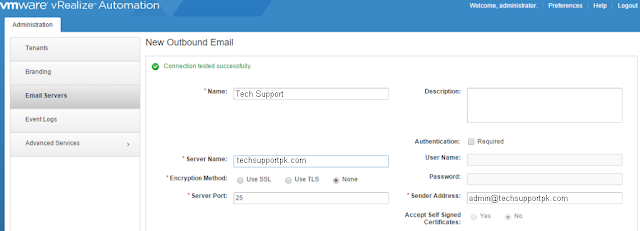
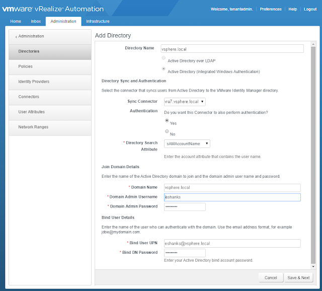
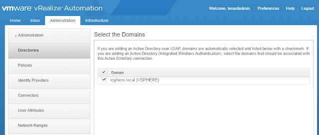
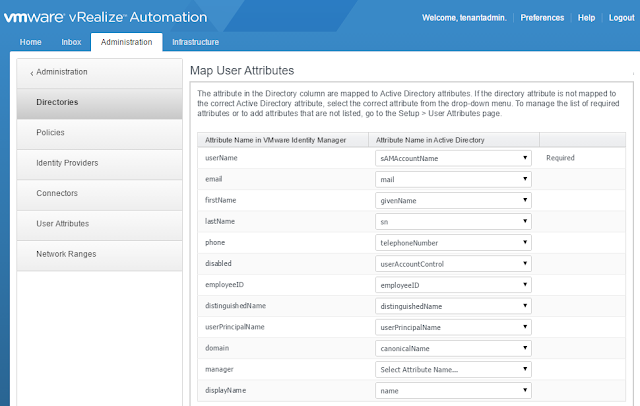
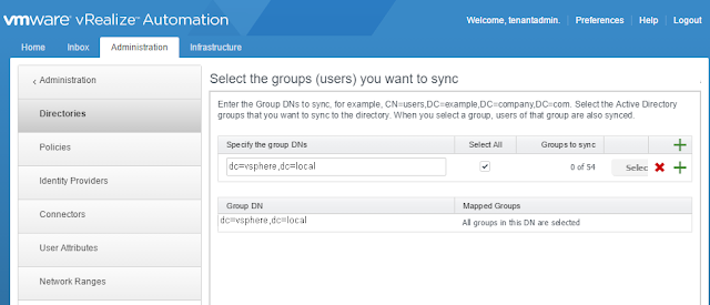


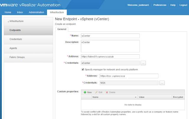
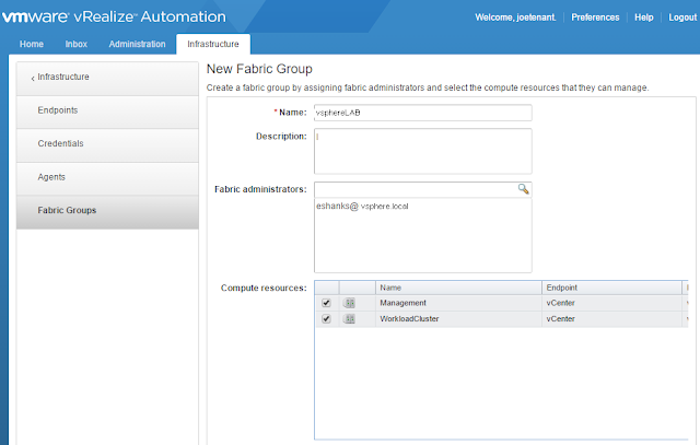
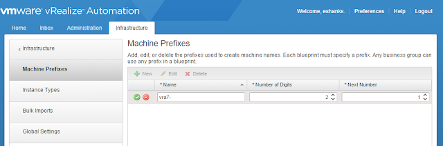
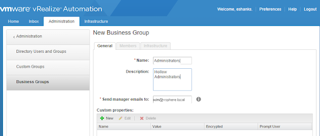
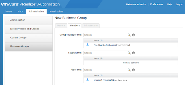

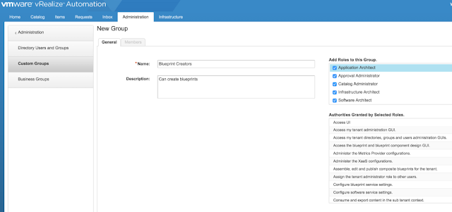
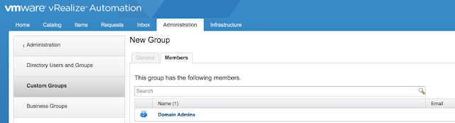
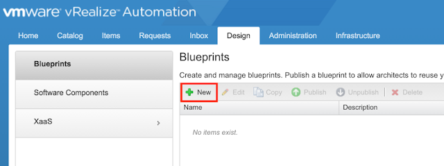
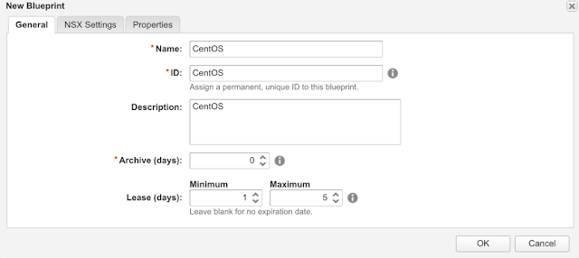
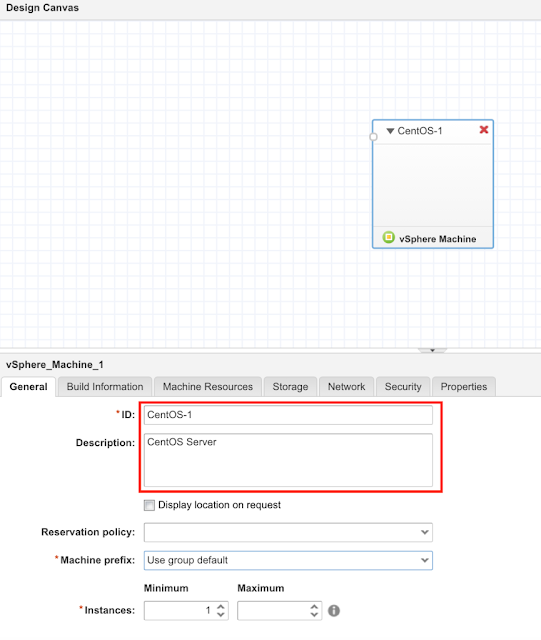
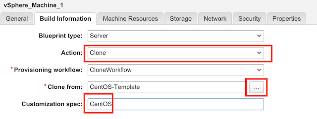
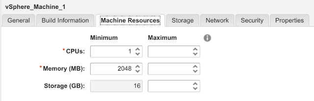
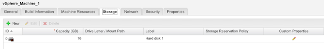
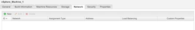
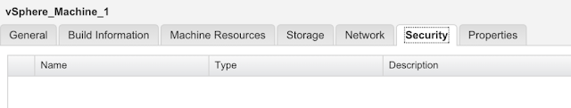
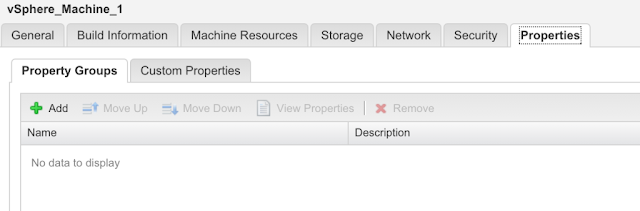
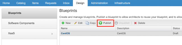
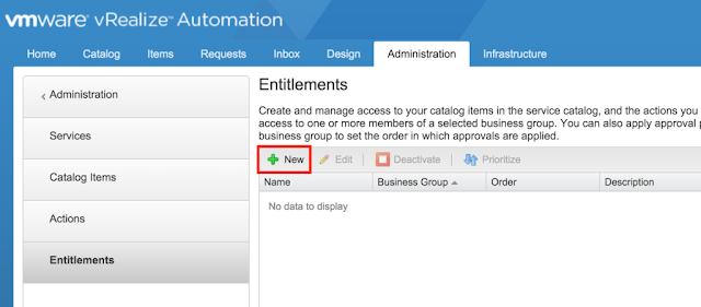
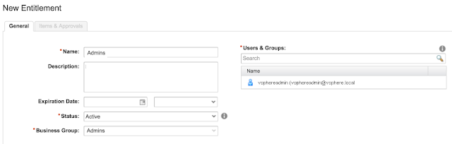
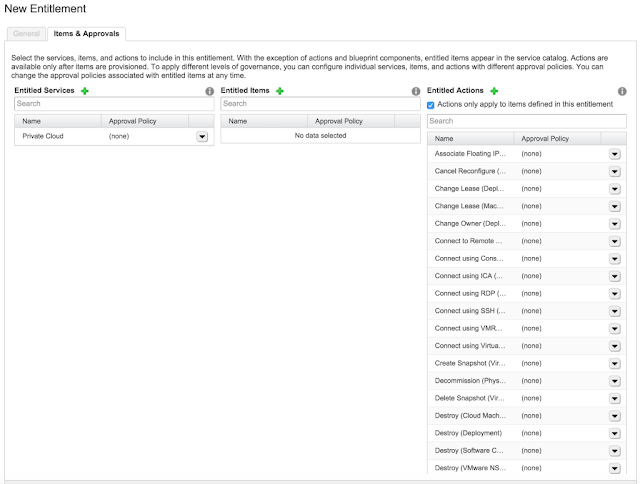
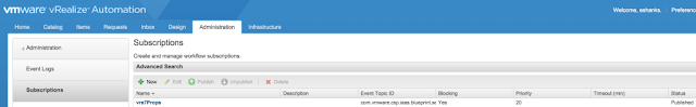

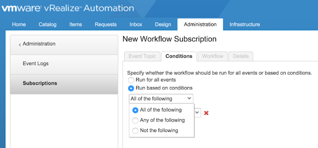
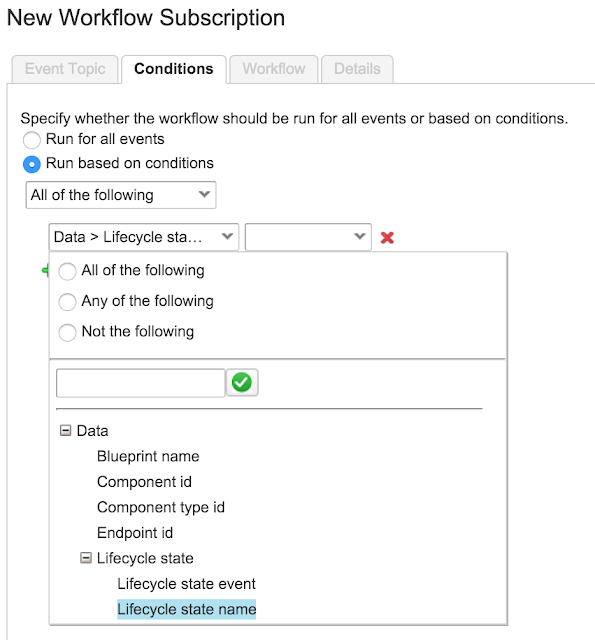
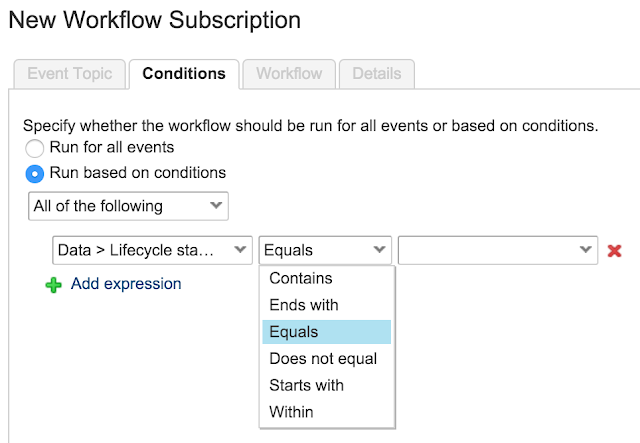
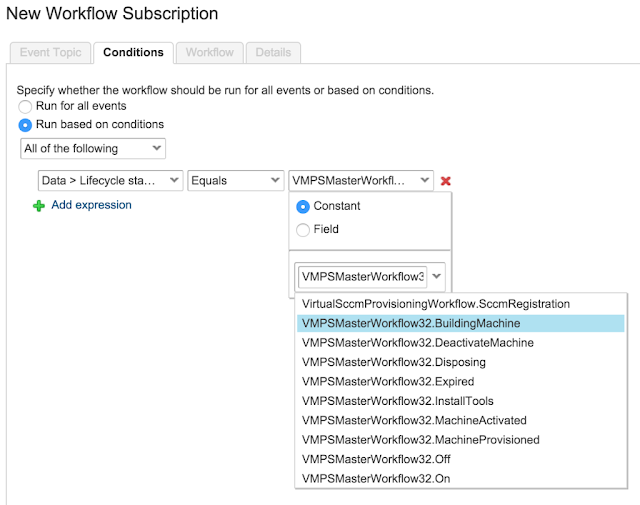
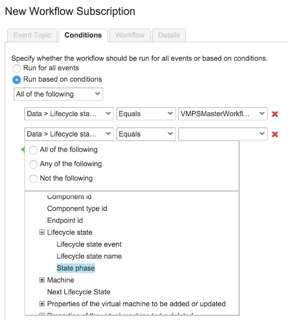
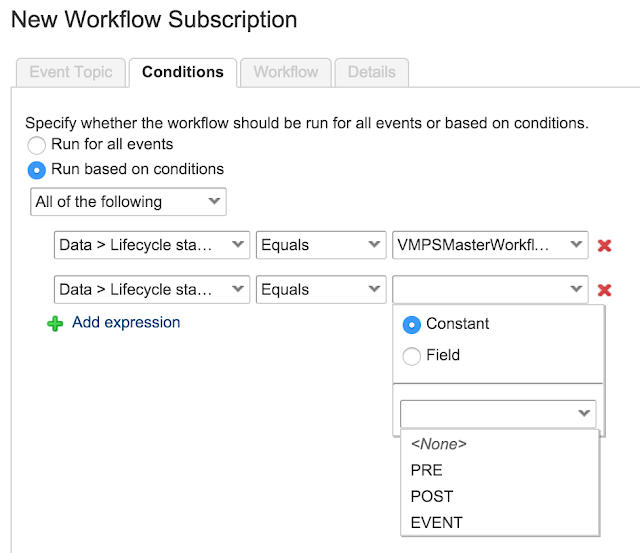
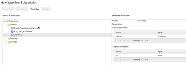
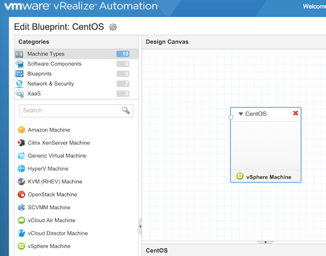
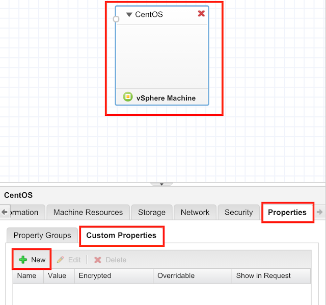
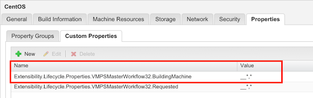
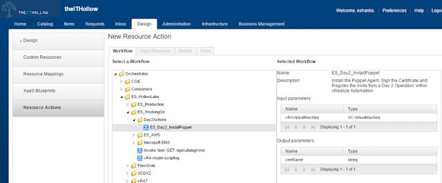

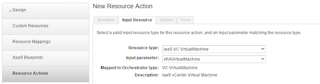
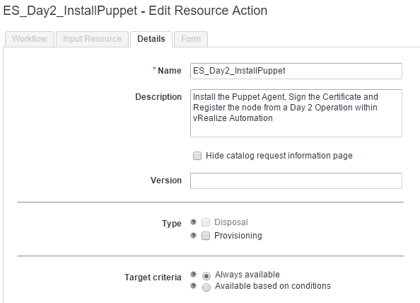

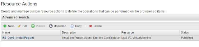
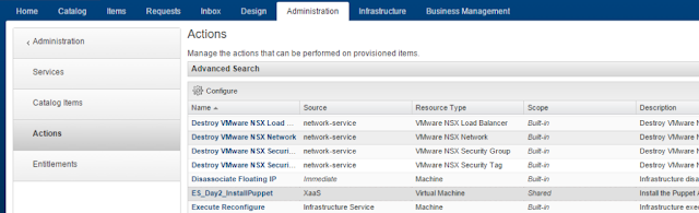
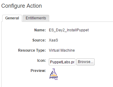
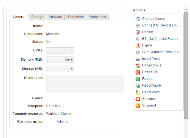
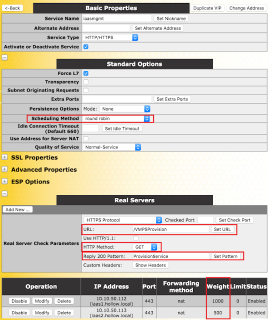
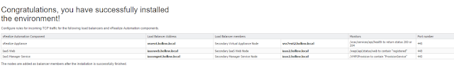
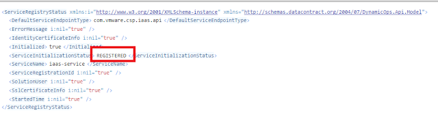
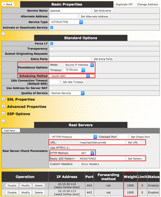
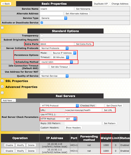
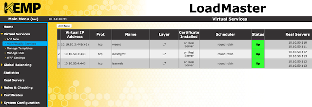
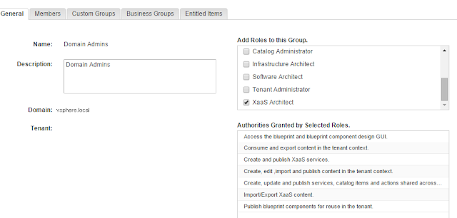
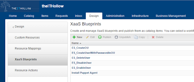

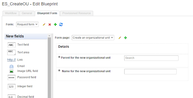
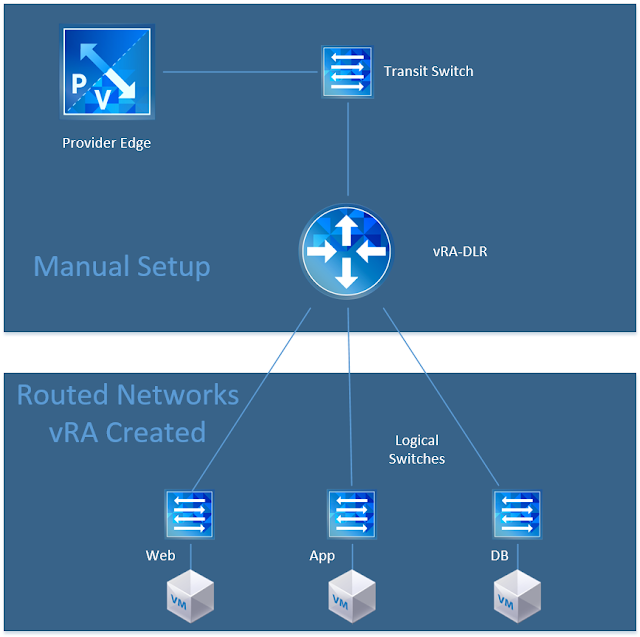


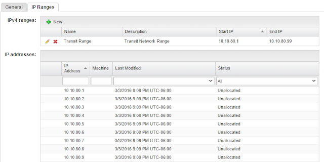
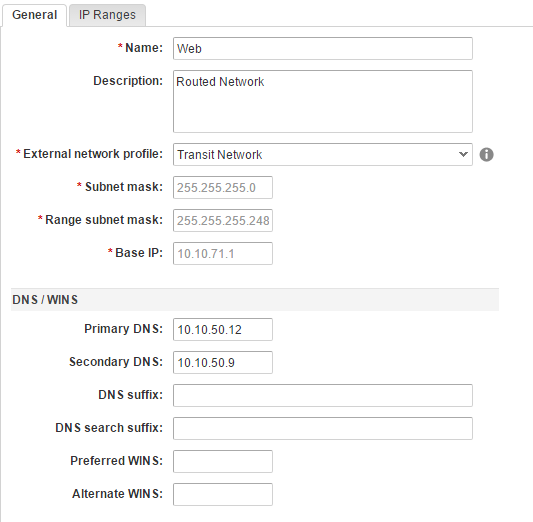
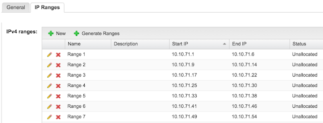


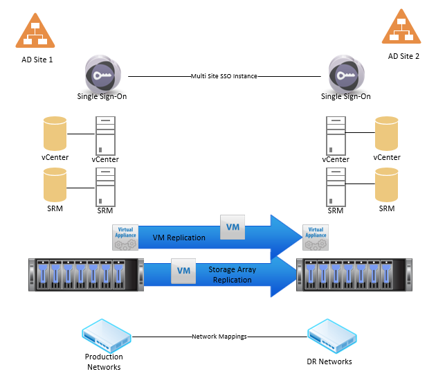
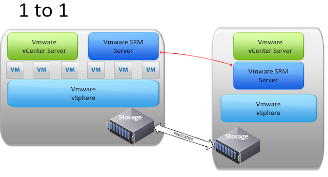
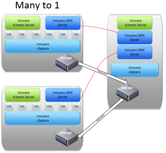
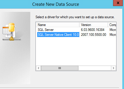
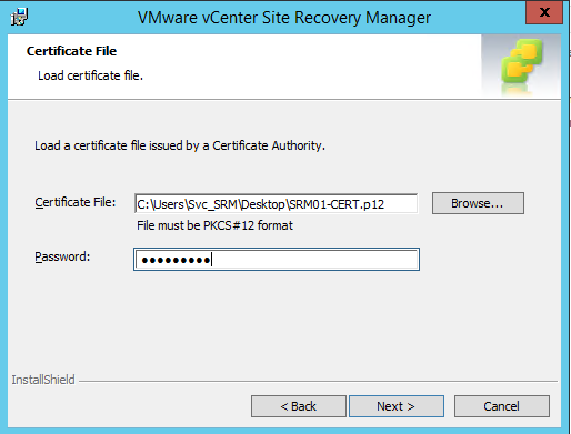
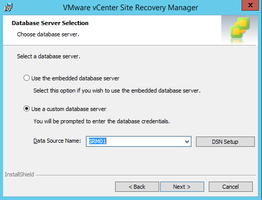
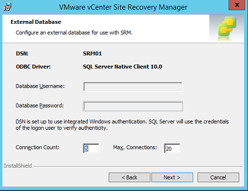

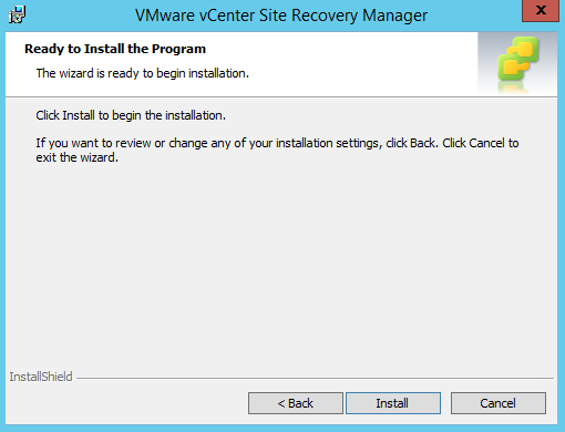

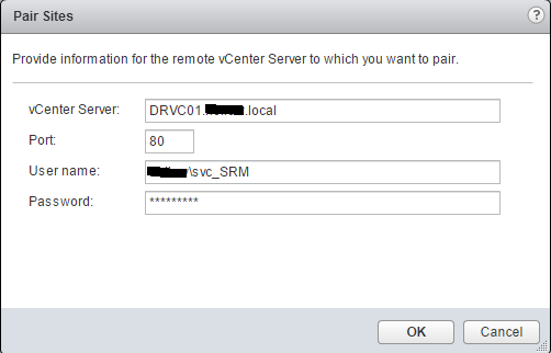
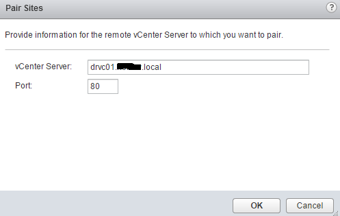
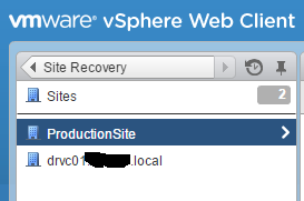
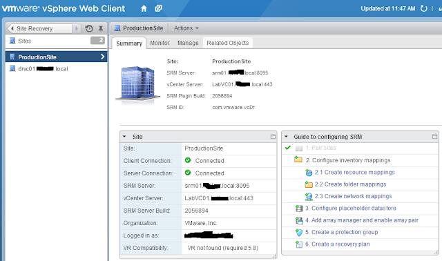
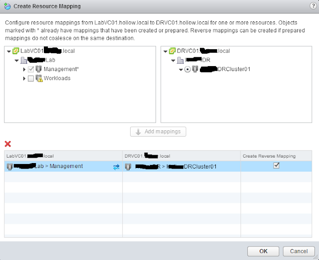
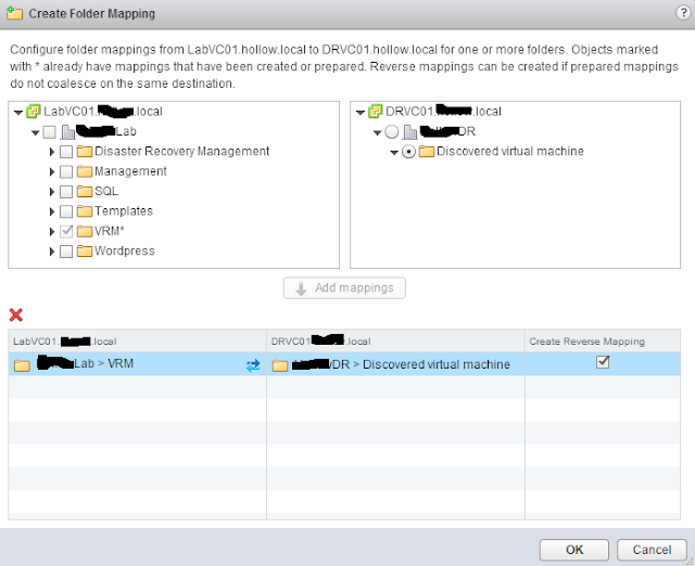
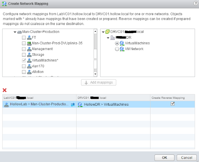
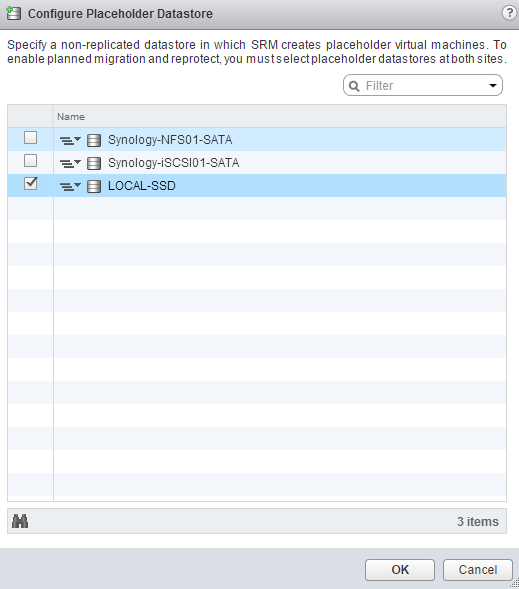
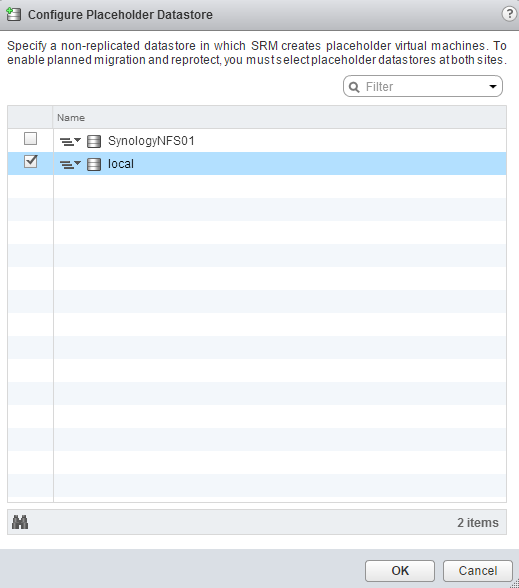
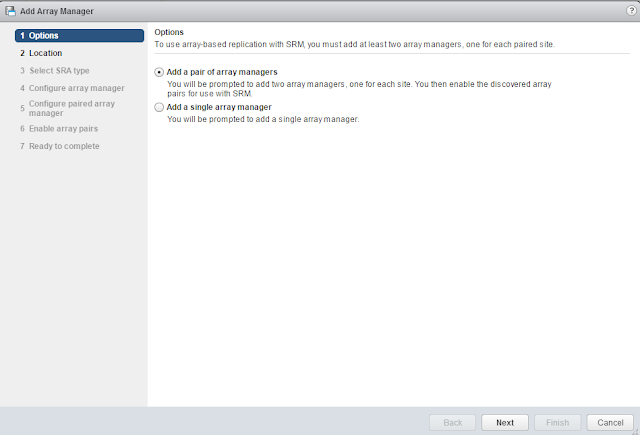
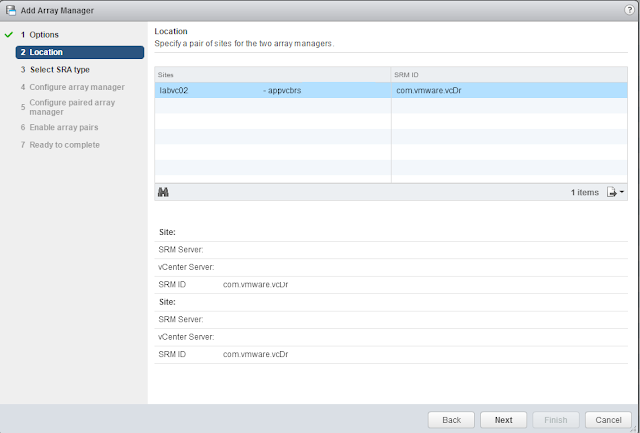
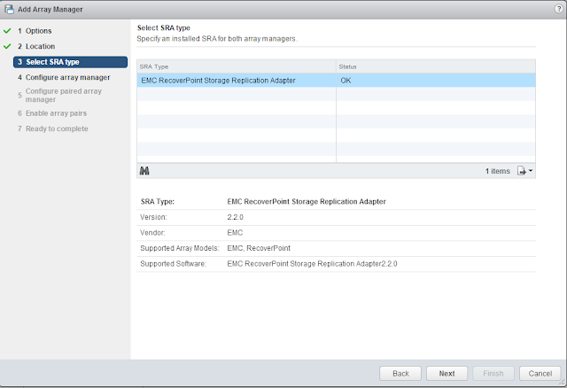
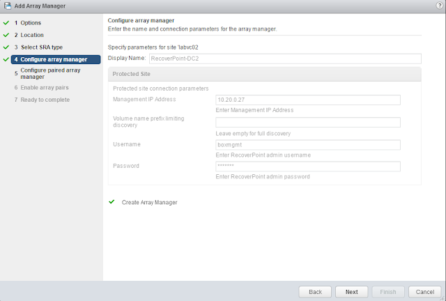
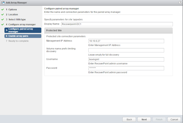
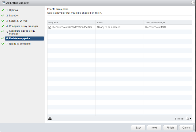
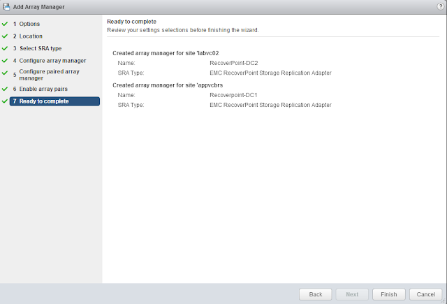
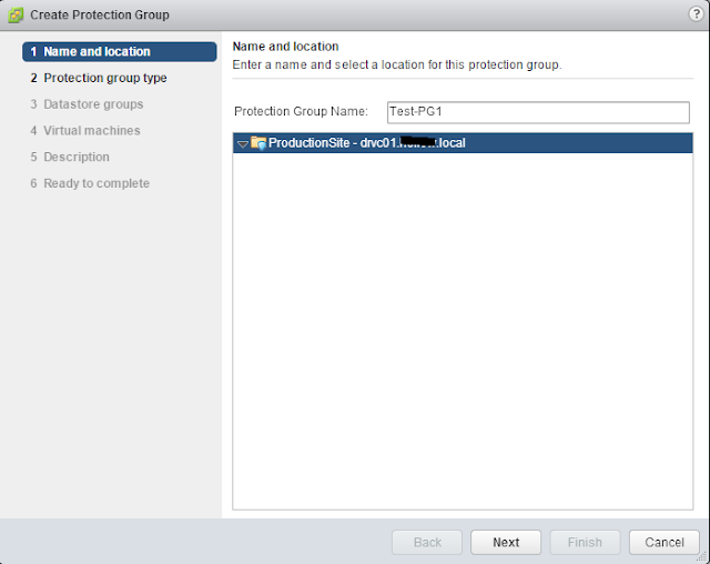
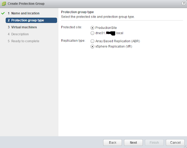
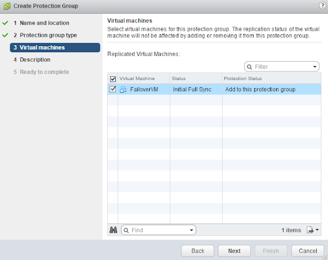
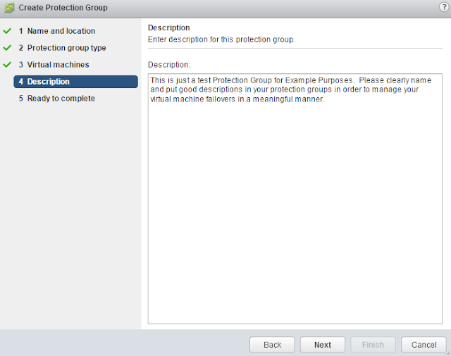

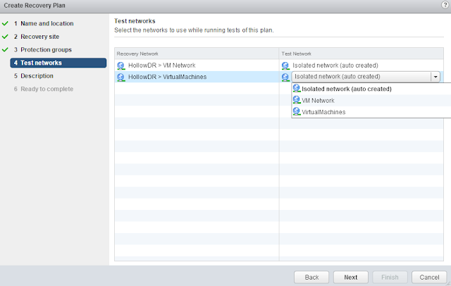
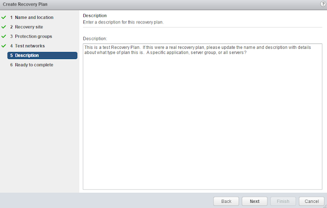
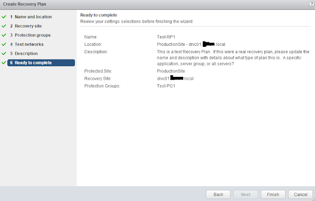
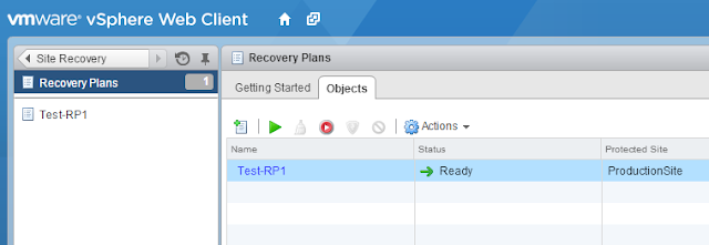
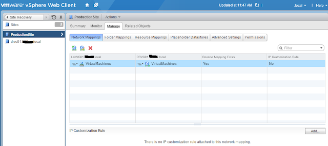
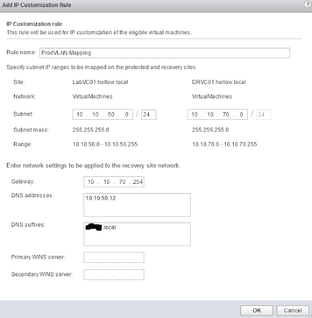
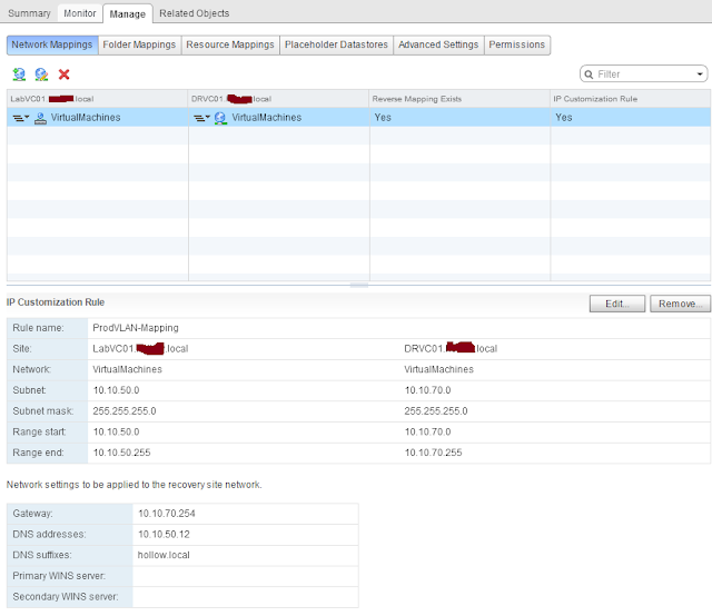
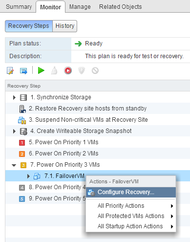
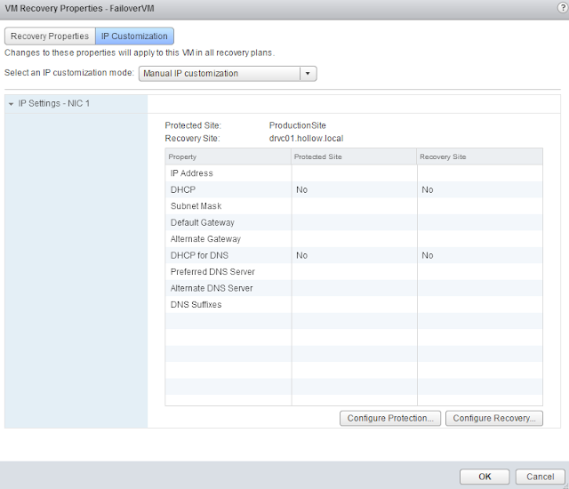
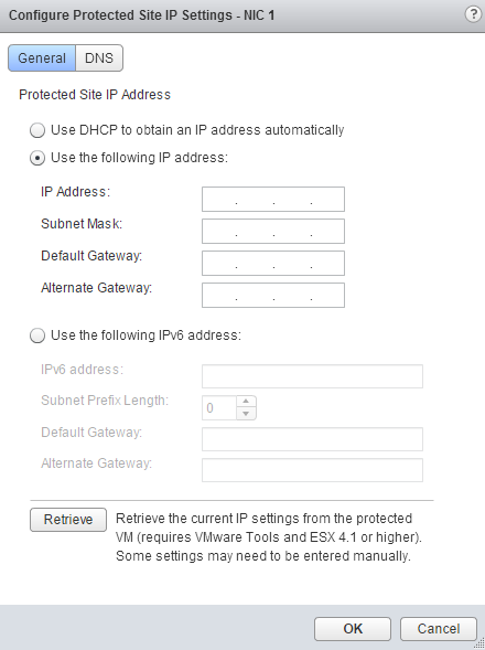
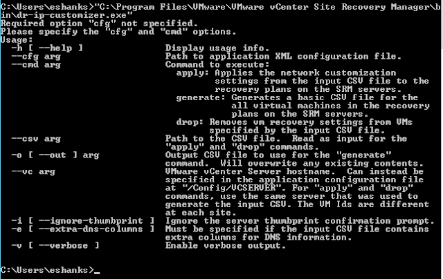
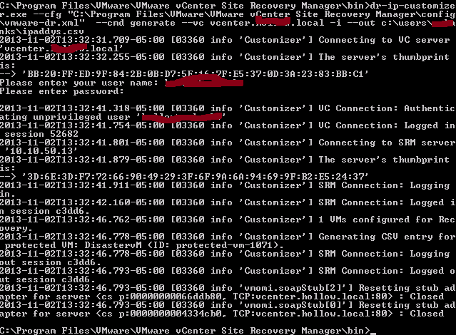
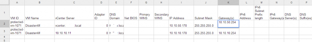


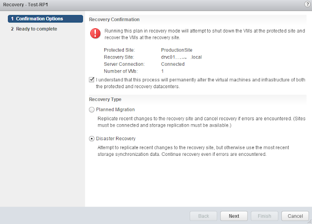

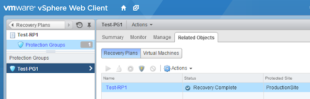
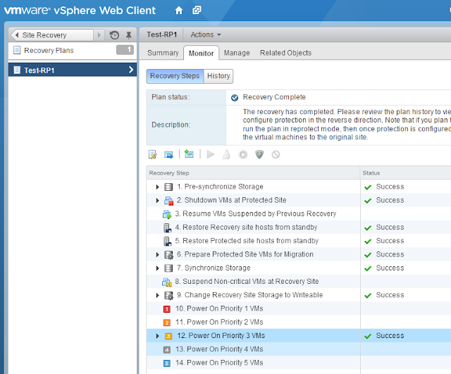
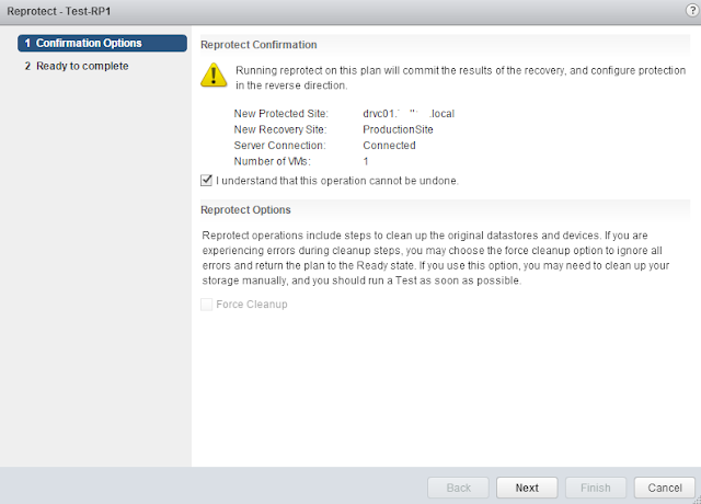
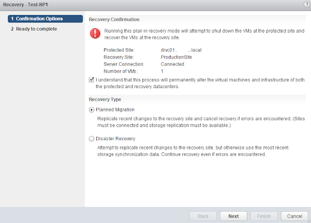
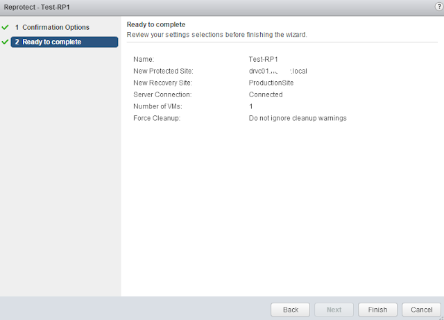
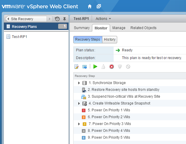


 Figure 3‑36: Currently Blocked Users


 ) to the right of the number in the first column. This expands the view to show the statistics for each Virtual Service on the Real Server.


 in the Virtual Services panel. This opens the Virtual Services configuration window.
 button within the window itself.
 button within the window itself.


 Figure 6‑4: Section of the Path Information screen


 icons.


 icons.


 , in the top right-hand corner of the screen.