Quantcast
Channel: Tech Support
Viewing all 880 articles
Browse latest View live

How to Migrate from Exchange 2010 to Exchange 2016 (Part 2)

$
0
0
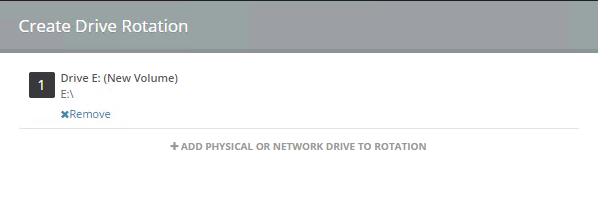
In this multi-part article we will migrate from Exchange 2010 to Exchange 2016. We’ll now create our first volume for the Page File. In our design, this is not to be located on a mount point, so we don’t need to create a folder structure to support it.
If you would like to read the other parts in this article series please go to:


Preparing the server for Exchange 2016


Configuring disks

We’ll now create our first volume for the Page File. In our design, this is not to be located on a mount point, so we don’t need to create a folder structure to support it. We can simple right click and choose New Simple Volume:

Figure 1: Creating a new volume for the page file

The New Simple Volume Wizard will launch. We’ll be provided with the opportunity to assign our drive letter, mount in an empty folder (which we will use for the database and log volumes) or not to assign a drive letter or path. We’ll choose a drive letter, in this case, D:


Figure 2: Assigning a drive letter to our page file disk

After choosing the drive letter, we’ll then move on to formatting our first disk.

Figure 3: Formatting our page file disk

After formatting the page file volume, we will format and mount our database and log volumes.
The process to create the ReFS volume with the correct settings requires PowerShell.

An example function is shown below that we will use to create the mount point, create a partition and format the volume with the right setting.

function Format-ExchangeDisk
{
      param($Disk, $Label, $BaseDirectory="C:\ExchangeDatabases")
      New-Item -ItemType   Directory -Path   "$($BaseDirectory)\$($Label)"
      $Partition = Get-Disk -Number $Disk | New-Partition   -UseMaximumSize
      if ($Partition)
      {
          $Partition | Format-Volume   -FileSystem ReFS   -NewFileSystemLabel $Label   -SetIntegrityStreams:$False
          $Partition | Add-PartitionAccessPath   -AccessPath "$($BaseDirectory)\$($Label)"
      }
}


Check and alter the script for your needs. To use the function, paste the script into a PowerShell prompt. The new function will be available as a cmdlet, Format-ExchangeDisk.

Before using the script we need to know which disks to format. In Disk Management examine the list of disks. We’ll see the first one to format as ReFS is Disk 2:

Figure 4: Checking the first disk number to use for Exchange data

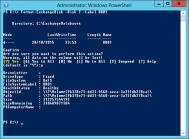
Format the disk using the PowerShell function we’ve created above:

Figure 5: Formatting an Exchange data disk using ReFS

After formatting all disks, they should show with correct corresponding labels:

Figure 6: Viewing disks after formatting as ReFS


Configuring Page file sizes

Page file sizes for each Exchange Server must be configured correctly. Each server should have the page file configured to be the amount of RAM, plus 10MB, up to a maximum of 32GB + 10MB.
To configure the Page file size, right click on the Start Menu and choose System:

Figure 7: Accessing system settings

The system information window should open within the control panel. Choose Advanced system settings, as shown below:

Figure 8: Navigating to Advanced system settings

Next, the System Properties window will appear with the Advanced tab selected. Within Performance, choose Settings:

Figure 9: Opening Performance settings

We will then adjust the Virtual Memory settings and perform the following actions:
  • Unselect Automatically manage paging file size for all drives
  • Set a page file size to match the current virtual machine RAM, plus 10MB, for example:
    • 8GB RAM = 8192MB RAM = 8202MB page file
    • 16GB RAM = 16384MB RAM = 16394MB page file
You’ll see the result of this for our virtual machine illustrated below:

Figure 10: Configuring the page file size

After making this change you may be asked to reboot.

You don’t need to do so at this stage as we will be installing some pre-requisites to support the Exchange installation.


Configuring Exchange 2016 prerequisites

To install the pre-requisites, launch an elevated PowerShell prompt, and execute the following command:

Install-WindowsFeature AS-HTTP-Activation, Desktop-Experience, NET-Framework-45-Features, RPC-over-HTTP-proxy, RSAT-Clustering, RSAT-Clustering-CmdInterface, RSAT-Clustering-Mgmt, RSAT-Clustering-PowerShell, Web-Mgmt-Console, WAS-Process-Model, Web-Asp-Net45, Web-Basic-Auth, Web-Client-Auth, Web-Digest-Auth, Web-Dir-Browsing, Web-Dyn-Compression, Web-Http-Errors, Web-Http-Logging, Web-Http-Redirect, Web-Http-Tracing, Web-ISAPI-Ext, Web-ISAPI-Filter, Web-Lgcy-Mgmt-Console, Web-Metabase, Web-Mgmt-Console, Web-Mgmt-Service, Web-Net-Ext45, Web-Request-Monitor, Web-Server, Web-Stat-Compression, Web-Static-Content, Web-Windows-Auth, Web-WMI, Windows-Identity-Foundation, RSAT-ADDS

After installation of the components a reboot is required before we can install the other pre-requisites needed for Exchange 2016 installation.

First we’ll install the .Net Framework 4.5.2.

Figure 11: Installing .Net Framework 4.5.2

Next, install the Microsoft Unified Communications Managed API Core Runtime, version 4.0.
After download, launch the installer. After copying a number of files required, the installer provides information about the components it will install as part of the Core Runtime setup:

Figure 12: Installing the Unified Comms Managed API

No special configuration is needed after install as it’s a supporting component used by Unified Messaging.
Our final pre-requisite is to download and extract the Exchange 2016 installation files themselves.

At the time of writing, the latest version of Exchange 2016 is the RTM version.

Note that because each Cumulative Update and Service Pack for Exchange 2016, you do not need to install the RTM version and update if a CU/SP has been released. Download the latest version available.

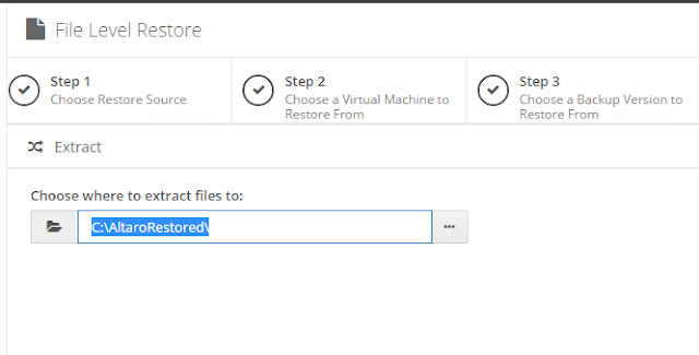
After download, run the self-extracting executable and choose an appropriate location to extract files to:
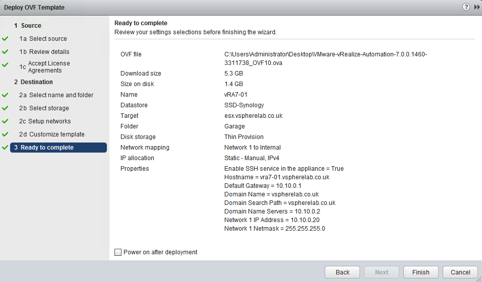
Figure 13: Extracting the files for Exchange 2016


Installing Exchange Server 2016

We will install Exchange Server 2016 via the command line. It’s also possible to perform the setup using the GUI, however the command line options allow us to perform each critical component, such as schema updates, step-by-step.


Installation Locations

As recommended by the Exchange 2016 Role Requirements Calculator, we will be placing the Transport Database - the part of Exchange that temporarily stores in-transit messages - on the system drive, therefore it makes a lot of sense to use the default locations for Exchange installation.

The default installation location for Exchange 2016 is within C:\Program Files\Microsoft\Exchange Server\V15.


Preparing Active Directory

Our first part of the Exchange 2016 installation is to perform the Schema update. This step is irreversible; therefore, it is essential that a full backup of Active Directory is performed before we perform this step.

While logged on as a domain user that's a member of the Enterprise Admins and Schema Admins, launch an elevated command prompt and change directory into the location we've extracted the Exchange setup files, C:\Exchange2016.

Execute setup.exe with the following switches to prepare the Active Directory schema:

setup.exe /PrepareSchema /IAcceptExchangeServerLicenseTerms


Figure 14: Preparing the schema for Exchange 2016

Expect the schema update to take between 5 and 15 minutes to execute.

Next prepare Active Directory. This will prepare the Configuration Container of our Active Directory forest, upgrading the AD objects that support the Exchange Organization. We'll perform this preparation using the following command:

setup.exe /PrepareAD /IAcceptExchangeServerLicenseTerms

Figure 15: Preparing Active Directory for Exchange 2016

Our final step to prepare Active Directory is to run the domain preparation.
Our smaller organization is comprised of a single domain, and therefore we can run the following command:

setup.exe /PrepareDomain /IAcceptExchangeServerLicenseTerms

Figure 16: Preparing the domain for Exchange 2016

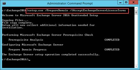
If you have more than one domain within the same Active Directory forest with mail-enabled users, then you will need to prepare each domain. The easiest way to prepare multiple domains is to replace the /PrepareDomain switch with /PrepareAllDomains.


Performing Exchange 2016 Setup

To install Exchange 2016 via setup.exe we will use the /Mode switch to specify that we will be performing an Install.

In addition to the /Mode switch we need to specify the role that we’ll install, the Mailbox role.

setup.exe /Mode:Install /Roles:Mailbox   /IAcceptExchangeServerLicenseTerms

Figure 17: Installing Exchange 2016 server

After a successful installation, reboot the server.


Summary

In part two of this series we have completed the server preparation and then installed Exchange Server 2016. In the next part of this series we will perform post installation checks and configuration.

If you would like to read the other parts in this article series please go to:


How to Migrate from Exchange 2010 to Exchange 2016 (Part 3)

$
0
0
In the first two parts of this series we performed the basic design and implementation of Exchange Server 2016 into our organization. In this part of the series, we’ll perform the first post-configuration steps.
If you would like to read the other parts in this article series please go to:

Post-Installation Configuration Changes


Checking Exchange After Installation

After installation completes we will ensure that the new Exchange Server is available.

Choose Start and launch the Exchange Administrative Center from the menu, or navigate using Internet

Explorer to https://servername/ecp/?ClientVersion=15:

Figure 1: Launching the EAC

When launching via a localhost URL and because we haven’t installed the real SSL certificate we will see a certificate warning, as shown below. Click Continue to this website to access the EAC login form:


Figure 2: First login to the EAC

You should see the Exchange Admin Center login form. Login using an organization admin credentials:

Figure 3: Login as an Admin to the EAC

After you successfully login, take a moment to navigate around each section of the EAC to familiarise yourself with the new interface.

Figure 4: Exploring the Exchange 2016 EAC

You’ll notice that the EAC is very different in layout to Exchange Server 2010’s Exchange Management Console. In Exchange 2010 and 2007, the focus was based on the organization, servers and recipients with distinct sections for each. Exchange 2013 and 2016 move to a more task-oriented view. For example, Send and Receive connectors are both managed from the Mail Flow section rather than hidden within respective Organization and Server sections.

However even with those changes, very similar commands are used within the Exchange Management Shell and you will be able to re-purpose any Exchange 2010 PowerShell skills learnt.


Updating the Service Connection Point for Autodiscover

After successfully installing Exchange Server 2016, a change worth making is to update the Service Connection Point (SCP).

The SCP is registered in Active Directory and used, alongside the Exchange 2010 SCP, as a location Domain-Joined clients can utilize to find their mailbox on the Exchange Server.

By default, the SCP will be in the form https://ServerFQDN /Autodiscover/Autodiscover.xml; for example https://EX1601.goodmanindustries.com/Autodiscover/Autodiscover.xml.

The name above however won't be suitable for two reasons - firstly, no trusted SSL certificate is currently installed on the new Exchange 2016 server, and the SSL certificate we'll replace it with in the next section won't have the actual full name of the server.

This can cause certificate errors on domain-joined clients, most commonly with Outlook showing the end user a certificate warning shortly after you install a new Exchange Server.

Therefore, we will update the Service Connection Point to use the same name as the Exchange 2010 uses for its Service Connection Point. This is also the same name we’ll move across to Exchange 2016 later on.
To accomplish this, launch the Exchange Management Shell from the Start Menu on the Exchange 2016 server:

Figure 5: Launch the EMS

To update the Service Connection Point, we'll use the Set-ClientAccessService cmdlet from the Exchange Server 2016 Management Shell, using the AutodiscoverServiceInternalURI parameter to update the actual SCP within Active Directory:

Set-ClientAccessService -Identity EX1601 -AutodiscoverServiceInternalURI   https://autodiscover.goodmanindustries.com/Autodiscover/Autodiscover.xml

Figure 6: Updating the SCP

After making this change, any clients attempting to use the Exchange 2016 Service Connection Point before we implement co-existence will be directed to use Exchange 2010.


Exporting the certificate as PFX format from Exchange 2010

Because we will migrate the HTTPS name from Exchange 2010 to Exchange 2016 we can re-use the same SSL certificate by exporting it from the existing Exchange server.

To perform this step, log in to the Exchange 2010 server and launch the Exchange Admin Console. Navigate to Server Configuration in the Exchange Management Console, select the valid SSL certificate with the correct name, then select Export Exchange Certificate from the Actions pane on the right hand side.

Figure 7: Exporting the Exchange 2010 SSL cert

The Export Exchange Certificate wizard should open. Select a location to save the Personal Information Exchange (PFX) file and an appropriate strong password, then choose Export:

Figure 8: Specifying an export directory and password

Make a note of this location, as we’ll use it in the next step.


Importing the Certificate PFX File

Back over on the Exchange 2016 server, open the Exchange Admin Center and navigate to Servers>Certificates. Within the more (…) menu choose Import Exchange Certificate:

Figure 9: Importing the SSL certificate to Exchange 2016

In the Import Exchange Certificate wizard we’ll now need to enter a full UNC path to the location of the exported PFX file, along with the correct password used when exporting the certificate from Exchange 2010:

Figure 10: Specifying the path to the Exchange 2010 server

After entering the location and password, we’ll then choose Add (+) to select our Exchange 2016 server, EX1601, as the server to apply this certificate to. We’ll then choose Finish to import the certificate:

Figure 11: Selecting appropriate servers to import the certificate to


Assigning the SSL certificate to services

Although we now have the SAN SSL certificate installed on the Exchange 2016 server it is not automatically used by services such as IIS, SMTP, POP/IMAP or Unified Messaging. We’ll need to specify which services we want to allow it to be used with.

To perform this step, within Certificates select the certificate and then choose Edit:


Figure 12: Assigning SSL certificates for use

Next, choose the Services tab in the Exchange Certificate window and select the same services chosen for Exchange 2010. In this example, we’re only enabling the SSL certificate for IIS (Internet Information Services):

Figure 13: Selecting services to assign the SSL cert to

After the certificate is assigned, ensure it is applied to IIS by running the following command:

iisreset /noforce


Configuring Exchange URLs using the Exchange Management Shell

The Exchange Management Shell also provides the functionality to change the Exchange URLs for each virtual directory, however unless you know the syntax it can be a little intimidating - and even if you do know the relevant syntax, typing each URL can be a little time consuming too.

We can use a PowerShell script to make this process simpler.

The first two lines of the script are used to specify the name of the Exchange 2016 server, in the $Server variable, and the HTTPS name used across all services in the $HTTPS_FQDN variable.
The subsequent lines use this information to correctly set the Internal and External URLs for each virtual directory:

$Server = "ServerName"
$HTTPS_FQDN = "mail.domain.com"
Get-OWAVirtualDirectory -Server $Server | Set-OWAVirtualDirectory -InternalURL   "https://$($HTTPS_FQDN)/owa" -ExternalURL   "https://$($HTTPS_FQDN)/owa"
Get-ECPVirtualDirectory -Server $Server | Set-ECPVirtualDirectory -InternalURL   "https://$($HTTPS_FQDN)/ecp" -ExternalURL   "https://$($HTTPS_FQDN)/ecp"
Get-OABVirtualDirectory -Server $Server | Set-OABVirtualDirectory -InternalURL   "https://$($HTTPS_FQDN)/oab" -ExternalURL   "https://$($HTTPS_FQDN)/oab"
Get-ActiveSyncVirtualDirectory -Server $Server | Set-ActiveSyncVirtualDirectory -InternalURL "https://$($HTTPS_FQDN)/Microsoft-Server-ActiveSync"  -ExternalURL "https://$($HTTPS_FQDN)/Microsoft-Server-ActiveSync"
Get-WebServicesVirtualDirectory -Server $Server | Set-WebServicesVirtualDirectory -InternalURL "https://$($HTTPS_FQDN)/EWS/Exchange.asmx"  -ExternalURL "https://$($HTTPS_FQDN)/EWS/Exchange.asmx"
Get-MapiVirtualDirectory -Server $Server | Set-MapiVirtualDirectory -InternalURL   "https://$($HTTPS_FQDN)/mapi" -ExternalURL   https://$($HTTPS_FQDN)/mapi

In the example below, we've specified both our server name EX1601 and HTTPS name mail.goodmanindustries.com and then updated each Virtual Directory accordingly:


Figure 14: Updating URL values


Configuring Outlook Anywhere

After updating the Virtual Directories for Exchange, we'll also update the HTTPS name and authentication method specified for Outlook Anywhere.

As Outlook Anywhere is the protocol Outlook clients will use by default to communicate with Exchange Server 2016, replacing MAPI/RPC within the LAN, it's important that these settings are correct - even if you are not publishing Outlook Anywhere externally.

During co-existence it's also important to ensure that the default Authentication Method, Negotiate, is updated to NTLM to ensure client compatibility when Exchange 2016 proxies Outlook Anywhere connections to the Exchange 2010 server.

To update these values, navigate to Servers and then choose Edit against the Exchange 2016 server:

Figure 15: Locating Outlook Anywhere settings

In the Exchange Server properties window choose the Outlook Anywhere tab. Update the External Host Name, Internal Host Name and Authentication Method as shown below:

Figure 16: Updating Outlook Anywhere configuration

Naturally you can also accomplish this with PowerShell, however it's just as quick to use the Exchange Admin Center for a single server.

With these settings configured, along with iisreset /noforce to ensure configured is re-loaded into IIS we could in theory move client access across from Exchange 2010 to Exchange 2016. Before we do that we will first make some additional configuration changes.


Summary

In part three of this series, we’ve performed the first basic configuration required for our Exchange 2016 server post-installation. In part four we will complete the post-installation configuration and begin preparation for migration.

If you would like to read the other parts in this article series please go to:


How to Migrate from Exchange 2010 to Exchange 2016 (Part 4)

$
0
0
In the previous article in this series, we began the post installation configuration of Exchange 2016 and made changes to client access. In this part of the series we will configure transport and mailbox databases, then begin preparing for the migration from Exchange 2010.
If you would like to read the other parts in this article series please go to:

Completing Post Installation Configuration


Configuring Receive Connectors

We’ll need to ensure that the same settings are applied to Receive Connectors on Exchange 2016 as per Exchange 2010. Default and Client connectors are already created and do not typically need to be altered. The defaults for Exchange Server 2016 allow email from the internet or spam filter to be delivered without adding an additional permission.

Many organizations do allow users to relay mail through Exchange from application servers, so we will use this as an example to illustrate how the process is slightly different when compared to Exchange 2010.
To begin, launch the Exchange Admin Center and navigate to Mail Flow>Receive Connectors and after selecting the Exchange 2016 server from the list, then choose Add (+) to create a new Receive Connector:


 Figure 1: Creating a new Receive Connector

On the first page of the wizard, enter the name for the receive connector. For consistency we’ve specified the server name after entering Anonymous Relay.

Select Frontend Transport as the role and choose Custom as the type:

 Figure 2: Naming the connector and specifying core options

On the next page, we'll be provided with the opportunity to specify Network Adapter Bindings - the IP address and TCP/IP port that the receive connector will listen on. Our example receive connector will listen on the standard port for SMTP, port 25:

 Figure 3: Leaving TCP/IP listener settings as default

On the final page of the wizard, we'll choose which IP addresses that the receive connector will accept mail for.

This allows multiple receive connectors to listen on the same TCP/IP port and IP address and perform an action depending on the remote IP address of a client.

As an example, if our anonymous connector on Exchange 2010 only allowed mail relay from the IP addresses 192.168.15.1-20, we'll specify that range here:

 Figure 4: Specifying IP addresses that can use this connector

After completing the wizard, we will then open the new Receive Connector’s properties page by selecting it from the list, then choosing Edit, as shown below:

 Figure 5: Editing connector settings after creation

In the Exchange Receive Connector window, select the Security tab. Then within the Authentication section select Externally secured to indicate our anonymous relay is from secure IPs; then under Permission Groups, choose Exchange Servers and Anonymous users:

 Figure 6: Allowing anonymous relay


Moving Default Mailbox Databases

We will move the initial database created by Exchange Server 2016 setup and make it our first Mailbox Database.

To perform this action, we will perform a two-step process using the Exchange Management Shell.
First, launch the Exchange Management Shell and use the following command to rename the database to DB01:

Get-MailboxDatabase -Server | Set-MailboxDatabase -Name DB01

 Figure 7: Renaming the default database

In the example above you'll see that by executing the Get-MailboxDatabase cmdlet before making the change we see its default name – “Mailbox Database” with a random suffix. After making the change, the name is changed to something more appropriate.

With the database name changed, it still remains in the same location. Move both the Database file and the associated log files to their respective final destinations using the Move-DatabasePath cmdlet with the -EdbFilePath and -LogFolderPath parameters:

Move-DatabasePath -Identity DB01 -EdbFilePath C:\ExchangeDatabases\DB01\DB01.EDB -LogFolderPath C:\ExchangeDatabases\DB01_Log
Figure 8: Moving the default database path

When moving the database, it will be dismounted. The files will then be moved to the new location and the database and log locations updated in Active Directory. Finally the database will be re-mounted.


Creating Additional Mailbox Databases

Next, create additional Mailbox Databases to match our design specifications. We can create the mailbox databases using either the Exchange Admin Center or the Exchange Management Shell.

In this example we will use the Exchange Management Shell, which for a larger number of databases will be faster and more accurate.

The cmdlets used are New-MailboxDatabase, Restart-Service, Get-MailboxDatabase and Mount-Database.

In the example shown below we will use the first cmdlet to create the databases, restart the Information Store to ensure it allocates the correct amount of RAM, then after retrieving a list of all databases we will ensure they are mounted:

New-MailboxDatabase -Name DB02 -Server -EdbFilePath C:\ExchangeDatabases\DB02\DB02.EDB -LogFolderPath C:\ExchangeDatabases\DB02_Log
New-MailboxDatabase -Name DB03 -Server -EdbFilePath C:\ExchangeDatabases\DB03\DB03.EDB -LogFolderPath C:\ExchangeDatabases\DB03_Log
New-MailboxDatabase -Name DB04 -Server -EdbFilePath C:\ExchangeDatabases\DB04\DB04.EDB -LogFolderPath C:\ExchangeDatabases\DB04_Log
Restart-Service MSExchangeIS
Get-MailboxDatabase -Server | Mount-Database

 Figure 9: Creating additional databases


Configuring Mailbox Database Settings

After we have moved our first Mailbox Database and created our additional mailbox databases, we will now need to configure each database with the correct limits.

The limits chosen for our example environment are shown below, along with retention settings for mailboxes:

Warning LimitProhibit Send LimitProhibit Send/Receive LimitKeep Deleted Items for (days)Keep Deleted Mailboxes for (days)
4.8GB4.9GB5GB1430

It’s possible to configure this using the Exchange Admin Center, but for multiple databases, use Exchange Management Shell to ensure consistency. Using a combination of the Get-MailboxDatabase cmdlet and Set-MailboxDatabase cmdlet make the changes, using the values from the table above:

Get-MailboxDatabase -Server | Set-MailboxDatabase -IssueWarningQuota 4.8GB -ProhibitSendQuota 4.9GB -ProhibitSendReceiveQuota 5GB -DeletedItemRetention "14:00:00" -MailboxRetention "30:00:00"

 Figure 10: Updating mailbox database settings


Preparing for Exchange 2016 Migration


Testing base functionality

Before we can move namespaces and mailboxes across to Exchange Server 2016 we need to test that the new server is fully functional.

We'll start by creating a test mailbox to use on Exchange 2016. To do this, navigate to the Exchange Admin Center and within Recipients choose Add, then User Mailbox:

 Figure 11: Creating a test mailbox

There is no prescriptive name for a basic test account, so enter suitable unique and identifiable details:


 Figure 12: Specifying test mailbox settings

After creating our test mailbox we’ll now need to test that they are functional from a client perspective.
Navigate to OWA via the server’s name. As a minimum test mail flow works correctly between our new Exchange 2016 test user and existing Exchange 2010 users.

 Figure 13: Testing OWA and other services


Updating Exchange 2010 Virtual Directory URLs

Exchange 2016 supports acting as a proxy for Exchange 2010 services. This means that it is easy to allow Exchange 2010 and Exchange 2016 to co-exist using the same URLs.

We decided earlier in this guide that we would use the same names for both Exchange 2016 and 2010.
It is now time to move the autodiscover.goodmanindustries.com and mail.goodmanindustries.com names across from Exchange 2010 to Exchange 2016.

This, along with the respective DNS / firewall changes, will result in HTTPS client traffic for Exchange 2010 going via the Exchange 2016 server.

We will update our core URLs for Exchange 2010 to remove the ExternalURL value. We'll also enable Outlook Anywhere, configuring it with the HTTPS name that will move to Exchange 2016.
To do this we will login to the Exchange 2010 server and launch the Exchange Management Shell. Enter the following PowerShell commands, substituting the $Server and $HTTPS_FQDN variables for appropriate values.

$Server = "EX1401"
$HTTPS_FQDN = "mail.goodmanindustries.com"
Get-OWAVirtualDirectory -Server $Server | Set-OWAVirtualDirectory -ExternalURL $null
Get-ECPVirtualDirectory -Server $Server | Set-ECPVirtualDirectory -ExternalURL $null
Get-OABVirtualDirectory -Server $Server | Set-OABVirtualDirectory -ExternalURL $null
Get-ActiveSyncVirtualDirectory -Server $Server | Set-ActiveSyncVirtualDirectory  -ExternalURL $null
Get-WebServicesVirtualDirectory -Server $Server | Set-WebServicesVirtualDirectory  -ExternalURL $null
Enable-OutlookAnywhere -Server $Server -ClientAuthenticationMethod Basic -SSLOffloading $False -ExternalHostName $HTTPS_FQDN -IISAuthenticationMethods NTLM, Basic

Figure 14: Updating Exchange 2010 URL and Outlook Anywhere configuration

From a client perspective this should not have any immediate effect. The Exchange 2016 server will provide External URL values via Autodiscover, but in the meantime client traffic will still be directed at the Exchange 2010 staging server.


Updating Internal DNS records and switching external HTTPS connectivity

To direct traffic internally at the Exchange 2016 server we need to change internal DNS records so that both the Autodiscover name and HTTPS namespace (in our case, mail.goodmanindustries.com) are configured with the IP address of the new Exchange 2016 server.

On a server with access to DNS Manager, such as an Active Directory domain controller, update both records from the IP address of the Exchange 2010 server to the Exchange 2016 server:

Figure 15: Updating internal DNS entries

Clients will not be immediately redirected to use the Exchange 2016 server as the proxy for client access, and instead will do so once their cached records expire. As soon as clients can access the server retry login and client access to ensure no issues exist.

If internal access works without issue, update the external HTTPS publishing - which in our example organization is a NAT rule configured via the router.


Summary

In part four of this series, we’ve completed the post-install configuration and began preparation for the migration. Base functionality has been tested and we have updated records to direct client access to the server. In the next part of this series we’ll begin by updating mail flow.

If you would like to read the other parts in this article series please go to:


What An eSim Is And How It Affects You

$
0
0

The SIM card as we know it could soon come to an end. There’s a new SIM in town, and it wants to make switching carriers a lot easier for everyone. Apple and Samsung are for getting rid of the physical SIM, but it’s not just them. Other companies such as AT&T, China Unicom, Verizon, Vodafone, and Orange are for the eSIM. We have to see what’s behind this eSIM and if everything is as good as they make it seem.


When the eSIM becomes available, it’s going to be an electronic SIM card that is not going to depend on the old method of introducing it to a device to work; it will already come built into the device. It’s a new standard from the GSMA, and the information it has is going to be rewritable or submissive by all operators.
The advantages that the eSIM is going to offer users is that it is going to make things a lot easier when we want to switch carriers or data plans within our current carrier. You will also save a lot of time if you ever wish to change your carrier since it can be done with a simple phone call.


Upgrading devices is also going to be a lot easier. For example, let’s say that your current device uses micro SIM, but the device you want to get uses nano SIM. In this situation switching devices and info can be a real fuss. With eSIM all you have to do is register the new device, and you’re done!
The eSIM is going to hold the profiles of all of the associated companies, but only the ones you are using will be activated. Each profile will be a different company, just like every traditional SIM has its own carrier. It’s these profiles that are going to allow you to also have lines from a different carrier, just like you would in a device with two or even three SIM cards in the same device. For now, you can only have one profile activated, but the idea is to have multiple profiles running simultaneously.
You can also say goodbye to roaming because once you land in a foreign country, you can easily get a local line while still having the line you’ve always had back home.

There are already some devices with eSIM (sort of), such as the Samsung Gear S2 smartwatch. The smartwatch features 3G connectivity, but you don’t have to open it to insert a SIM card – it is built in. This is going to allow more devices to be used as a phone, regardless of their size.


The eSIM craze is going to have two parts. The first part is going to affect the wearables, tablets, and other devices, while the second part is going to be exclusively for the smartphones. Thanks to the eSIM, you are going to be able to connect multiple devices to a single plan with the carrier you have chosen. We still have to wait and see when the second part starts, but some say that it will start in June while others say that it will begin by the end of 2017.

What if I have a smartphone with a traditional SIM card, will I be able to enjoy the benefits of the eSIM? Don’t worry, you will still be able to benefit from the eSIM since the carriers can reprogram your traditional SIM card to give it other parameters. To get a better idea of this, it will be like Apple’s white SIM cards.
If you buy a smartphone, tablet or smartwatch from a carrier, you can program your device right there at the store. But, if you get a device on your own, it’s also going to be easy. The carrier will have websites and apps set up where you can get a new line for your device.
Everything seems to indicate that the eSIM is something that is going to benefit us all, but only time will tell if there is something to fear about it. Do you think that the eSIM is something that will make things easier, or do you think it’s all part of an evil plan to keep us under control? 


How to Block SMS from Spammers on iPhone

$
0
0


I’m sure you get a lot of spam SMS messages, too – from all over the place. On Android an app like Truemessenger would take care of it. But on iPhone, we need to do a bit of manual labor.

If you just want to stop getting notifications for SMS from a contact, you should try muting them. To do this, go to the message thread for the sender you want to block, and tap the “Details” button on the top-right corner of the screen.

You’ll now see a “Do not disturb” option. Toggle the button next to it, and all notifications from this sender will be muted.


When you mute a sender, new messages will show up in the Messages app, but the conversation will have that half-moon DND icon next to it.
Sometimes, just muting a sender is not enough, especially when you know all you’re going to get from the sender is spam you don’t care about.

To block a sender, tap the “Details” button from the message thread and from this screen tap the “i” button next to the sender’s name.


Here at the bottom of the page you’ll see te “Block this Caller” option. Now tap the “Block Contact” confirmation popup, and the contact is now blocked.
Unlike muted senders, new messages from blocked senders won’t be shown in the Messages app at all. If at some point you want to view those messages, you’ll need to unblock them.

To do that, open the “Settings” app from the homescreen, go to “Phone” and then “Blocked.”


You’ll see all your blocked contacts here. Swipe left on a contact to reveal the “Unblock” button. Tapping it will unblock the contact.


Tips and Tricks to Make You a Better iPhoneographer

$
0
0

The best camera in the world is the one that you have with you.” Even a US$10,000 camera is useless

If you don’t bring it with you when you see a moment worth snapping. That’s why many people replace pocket cameras with smartphone’s cameras. And because the iPhone camera is among the best of the best camera phones available, iPhone Photography quickly has become an art itself. They call it iPhoneography.
Here are several things that you can do to get better photos with your iPhone.


As Apple continuously improves iPhone cameras with each iteration, it’s only logical that the newer your iPhone is, the better photo result you will get. But you can get even better photos if you use additional tools. They are optional, but obtaining a few (or all) of them doesn’t hurt either.


Tripod, Monopod, and other Pods

Carrying extra load might not be the idea of fun photography, but if you want to take better photos, you really could use the help of one of the pods to steady the camera. A tripod is an obvious choice, but even the smaller monopod – that is commonly used to take selfies – can help set your iPhone into a steadier stance. You can also try one of those flexible, portable tripods.


Special Lenses

The popularity of the iPhone camera has bred several special clip-on lenses that you can use to create different perspectives of your shots. The most popular types of these lenses are fisheye, wide, and macro.


Remote

Sometimes you need to put your camera away, and the shutter button is out of your hand’s reach: for example, when you need to take a selfie. You can do away with the camera timer, but the process will be easier if you have a remote shutter. The volume up button on your earphone can be your wired remote shutter button. Or, if you prefer no cable, you can acquire the bluetooth connected type.


The software part is as important as the hardware part in helping you get better pictures, both in taking the photos and editing them.


Camera Softwares

The latest rendition of Apple’s camera app is a solid one with enough features to satisfy most users. But there are alternative camera apps that you can try, such as Camera+ (US$2.99), VSCO Cam (free), Manual (US$2.99), and Slow Shutter Cam (US$1.99).


Picture Editing Software

What do you do with your pictures after you take them? You can edit them for better results – adjusting the color, cropping the image, adding filters, etc. There are literary tons of image editing apps available for iPhone, and it’s impossible to mention even a fraction of them. So I’ll just list two that I use: Snapseed (free) and Photolab (US$3.99)


Knowing few basic photography techniques won’t suddenly turn you into a pro, but it can improve your shots a lot. Among many, here are several that I think are easy enough to learn and applicable to amateur iPhoneographers.


Composition

Amateurs tend to put their photo objects in the center. While there’s nothing wrong with that, your pictures will look better and more natural if you use the rule of thirds and golden ratio to compose your photos. There are many references that you can find on the Internet about them, but here is the gist of it.

To use the rule of thirds, imagine that there are four lines (two down and two across) that divide your screen equally into nine areas. Align your subject(s) with the lines and intersections and you will be amazed at the result.

The rule of thirds’ grid in your iPhone is disabled by default. But you can enable it by going to “Settings -> Photos & Camera -> Grid” and switching it on.


The more advanced composition method that you can try is the golden ratio, also known as divine proportion. It’s derived from Fibonacci’s Ratio and has been said to create a pleasing feeling to human eyes.
Your iPhone camera app doesn’t come with the golden ratio feature, but Camera Awesome (free) does.


Lights and Shadows

Based on my amateurish iPhoneography experiment, you will get a better image with the light source in front of your subject and no nearby wall behind to show cast shadow. Also, natural daylight will always yield better results than non-natural light sources.

But that doesn’t mean that you can’t bend the rules. Experiment a lot to try to create different effects. Strong backlight covered by the object can create a great silhouette effect. You can also play with the shadow created by strong light.


Focus

It’s evident that out-of-focus photographs will never be the ones that you’re proud of, but you can use out-of-focus foreground and background to create the sense of depth. While it’s common knowledge that you can tap on an object on the iPhone screen to focus on it, not many of us know that you can lock the focus by doing a tap and hold.


There are many more tips to get better photos with your iPhone; the ones listed here barely scratch the surface. If you have a trick or two that you can share, you can use the comments below.


New Pipe: An Open Source Take on an Android YouTube App

$
0
0

Recently, YouTube has released YouTube RED, a new premium side of YouTube that allows users who pony up $9.99 a month access to some compelling features – things like offline playback, background playback and no advertisements (and original programming).

These features all seem reallly good, but
if you’re like most people, shelling out $9.99 for YouTube doesn’t seem like something you’d want to do. That’s where New Pipe comes in. It’s an open source front-end for YouTube. It copies a lot of features bundled with YouTube RED and is a very compelling YouTube replacement app.


The best thing about this app is that it takes some features from YouTube RED and gives them to you for free. Want to listen to a song on YouTube from your favorite YouTuber in the background? Just search for it in New Pipe and press the headphone button. You can even change the settings so it’ll use your external video or audio player app.


It also has support for downloading videos. Say you have a terrible Internet connection and can’t stream videos, but downloads are fine. Just find the videos you’d like to save, and press the Download button to save the files (again, just like YouTube RED).


Another killer feature is the ability to cast videos to Kodi via the “Play with Kodi” option. With this you’ll be able to blast YouTube videos from your Android to your Linux-powered media center. It’s very handy.


Along with playing back videos from YouTube in different ways, New Pipe has some other handy features. For example: the privacy-minded can force the video download traffic to flow through TOR. Streaming video files through this method is not ready yet, and the developer has not indicated when this feature will be added.
New Pipe can be installed in one of two ways. The first (recommended way) is to just install the F-Droid app store, and then search for New Pipe in the store to install it. Alternatively, you can just grab the app’s APK file directly from the F-Droid website.

Note: you’ll need to enable “Install from unknown sources” on your Android device before either installation method will work. This setting is (usually) located under “Settings > Security.”


Once the F-Droid app is installed, tap the Settings button at the top-right and look for “Update Repos.” Once you’ve tapped that, F-Droid will go out and update all repositories.


From there, just go to the search bar and type “New Pipe.” When you click on it in the search results, you’ll be taken to the app page. Click install, and you’re good to go.
New Pipe is perfect for those who casually like to watch YouTube. If you’re heavily invested in YouTube and the subscription model, it’s really this app’s only negative. There’s no main page filled with your YouTube subscriptions and no way to sign into your account. If you follow a lot of creators on YouTube, you’d be better off just going with YouTube RED.

However, if you don’t mind having to search out content manually, perhaps this is a good app for you. Of course, users could get the best of both worlds by using both the regular YouTube app (ad-supported with no extra features) along with New Pipe for background play, downloads and everything else it offers.


Seagate Reveals World's Fastest SSD

$
0
0
A depiction of Seagate's new hyperfast SSD, which will sport up to 16 I/O lanes and 10GBps speeds. The new SSD will be generally available this summer.


Seagate today announced what it's calling the world's fastest enterprise-class, solid-state drive (SSD), one that can transfer data at rates up to 10 gigabytes per second (GBps), some 6GBps faster than its previously fastest SSD.


While there were no specifics with regard to the SSD's read/write rates, capacities or pricing, the company did say the new drive meets the Open Compute Project (OCP) specifications. The OCP was launched in 2011 to allow the sharing of data center designs among IT vendors -- including Facebook, Intel, Apple, and Microsoft -- as well as financial services companies such as Bank of America and Fidelity.

A depiction of Seagate's 10GBps, 16-lane PCIe SSD, which will go on sale this summer and offer a 66% increase in performance over the company's previous PCIe/NVMe drive.

"Hypothetically a company like Netflix or YouTube or Hulu wants to maximize the speed at which they can deliver content, since it means they can serve more people at the same time," a Seagate spokesperson wrote in an email to Computerworld.. "Before, within a single card slot they could only get up to 6 GBps data throughput, but now in that same slot they can deliver 10 GBps. That comes to about two-thirds, or 66% increase in performance in the same slot, meaning they can theoretically deliver about 66% more streaming data per second."

Seagate said it plans to display the new SSD today at the OCP Summit in San Jose.


Seagate's new SSD is based on the non-volatile memory express (NVMe) interface, which was developed by a cooperative of more than 80 companies and released in March 2011. The NVMe specification defined an optimized register interface, command set and feature set for SSDs using the PCIe interface -- a high-speed serial computer expansion bus standard used in both enterprise and client systems.


Intel's SSD 750 series drive, which also uses the NVMe/PCIe interface. The SSD sports read speeds of up to 2,500MB per second or 2.5GB per second.

"The unit could be used in an all-flash array or as an accelerated flash tier with hard-disk drives (HDDs) for a more cost-effective hybrid storage alternative," Seagate stated in a news release about the new SSD.

The NVMe specification helps reduce layers of commands found in other standards, such as serial ATA (SATA), to create a faster, simpler language among flash devices.

Seagate's previously fastest SSD was the Nytro XP6500 flash accelerator card, an 8-lane PCIe SSD that had up to 4TB capacity and a maximum data transfer rate of 4GBps.
Seagate’s previous fastest SSD, the Nytro XP6500 flash accelerator card with a maximum data transfer rate of 4GBps.


The new 10GBps SSD technology accommodates 16-lane PCIe slots. Seagate is also developing a second unit for 8-lane PCIe slots, which still performs at 6.7 GBps, "and is the fastest in the eight-lane card category," Seagate said.

The 8-lane PCIe SSD will offer an less expensive alternative for businesses looking for the highest levels of throughput speed "but in environments limited by power usage requirements or cost," Seagate stated.

Both the 16 and 8-lane SSDs have already been made available to Seagate original equipment manufacturers and are expected to be generally available this summer.

BMW's Concept Car Wows With Shape-Shifting

$
0
0
BMW's latest concept car, timed to its 100-year anniversary, has shape-shifting sides and a steering wheel that folds into the dash.


How to Configure Mail Relay in Exchange Server 2016

$
0
0
In Exchange Server 2013 we went through several steps to configure relay using different network adapters and creating receive connectors. In this article we will keep it simple and configure the relay on the new Exchange Server 2016 in just a few steps.


By default, any Exchange Server 2016 is able to receive e-mails on all accepted domains configured at the organization level. That means that in theory we can configure a Firewall to publish the Public IP on 25 (TCP) port to the internal Exchange Server 2016 and the Internet mail flow will work just fine. By default, like all other previous versions, any new deployment of Exchange Server is secure out of the box and there is no risk of open relays using default settings.

Although it is possible to move all Internet traffic to the Exchange Server box, the recommendation is to subscribe to a Cloud Service, such as EOP (Exchange Online Protection) to perform all hygiene on the Internet and then move all the valid mail traffic to your on-premises environment, or an Edge Server/Antispam solution located at the DMZ.


Checking the built-in relay capabilities in Exchange Server 2016.

We can check the accepted domains using either Exchange Management Console or Exchange Admin Center (ECP). In the ECP, click on Mail flow, and then on Accepted domains (Figure 01); if you want to get the same information using Exchange Management Shell, you can use the following cmdlet (PowerShell on Figure 01)

Get-AcceptedDomains

 Figure 01

By default, any Exchange Server 2016 will have several connectors and based on the transport pipeline of the product (more details can be seen on this Microsoft article). The Receive Connector that we will be looking into is the Default Frontend , and in order to get there click on mail flow and then Receive Connectors, make sure to select the server from the Select Server list (Figure 02).

 Figure 02

Let’s test that connector, we will create a fake message from a bogus domain to our administrator account that exists on the Exchange Server organization (domain apatricio.local), and see if that message goes through.

The preferable method to test is using telnet utility to connect to the Exchange Server on the 25 port. The entire process is described below and shown in Figure 03. We are using just a couple of commands to test the mail flow. This Microsoft KB explains the entire process.

Note:
If you are using Windows 10/Windows Server 2012 R2 you won’t have Telnet client available out of the box. In order to install it open the PowerShell as administrator and run the following cmdlet: Add-WindowsFeature telnet-client.

telnet 25
Ehlo domain.ca
Mail from: andy@domain.ca
Rcpt to:administrator@patricio.local
Data


Subject: Test #01
This is a test message
.

 Figure 03

On the end-user side we can check and the result is a new message, as shown in Figure 04.

 Figure 04

That is great, we tested and validated the mail flow on the default receive connector. However, if we try to do the same thing using an external e-mail address we will get an error. In Figure 05, we are trying to send a message to a remote domain (Patricio.ca for example, which is a valid domain on the Internet), the error message that we get is 550 5.7.54 SMTP; Unable to relay recipient in non-accepted domain.

 Figure 05

From the security perspective that is really good, nobody will be able to use our Exchange Server 2016 to relay messages to other domains that we haven’t configured in our Exchange Organization, however for an internal service/application that needs to relay messages to external users, that is not good and we need to allow them to do that.


Creating a Receive Connector to allow relay to external addresses.

The most important thing here is to understand how Exchange works. We know for a fact that any attempt to relay to a valid accepted domain will work, so we are good for internal flow. That may be enough for the vast majority of applications including network devices (scanners, fax machines, and etc.).

In order to allow external relay, we need to create a receive connector. Logged on Exchange Admin Center (ECP), click on Mail flow, Receive Connectors and click on New.

In the new page (Figure 06), label the new receive connector and select Frontend Transport, and select Custom, and click Next.

 Figure 06

We can bound a receive connector to a specific adapter and/or port (Figure 07). In this case we will leave default settings which is listening on all IPs of the server and on the traditional 25 port. Click on Next.
Note:

Keep in mind that a unique set of IP Address/Port/Remote IP addresses is required for each Receive Connector. At the beginning of this article we pointed out that the server has already several Receive Connectors and by default they are always listening on all available IPv4 and in some specific ports.

 Figure 07

So far in this new receive connector, we have configured values that are already in place (Listening IP and port). The only way to escape an error when completing this wizard is to define the Remote network settings page with the IPs of the internal servers that will be able to relay messages to the outside world (Figure 08).

Note:That was the reason why we selected Custom at beginning of the wizard, because this page is displayed when that option is used. By doing that we make this Receive Connector unique and we can safely click on Finish.

 Figure 08

Before releasing to production/test, we need to work on two details on this newly created Receive Connector: Security and AD permissions.

The security can be done using Exchange Admin Center. Double click on the new receive connector, click Security, and we can start simple by selecting Anonymous users where we say that the relay will be open (not yet) without authentication. It is not the best practice or ideal but can be used in some controlled scenarios (Figure 09).

 Figure 09

The next step is to configure a specific permission at the Receive Connector level. If we run the Get-ReceiveConnector we will get a full list of all Receive Connectors, however we want to isolate the connector which we will apply the relay permission, and for we need to use \ after the cmdlet, as shown in Figure 10 and listed below.

Get-ReceiveConnector
Get-ReceiveConnector mtlex01\relay

 Figure 10


Having isolated the Receive Connector, we can apply the Active Directory Permission and we can use the following cmdlet (Figure 11).

Get-ReceiveConnector \ | Add-ADPermission –User “NT Authority\Anonymous Logon” –ExtendedRights “ms-Exch-SMTP-Accept-Any-Recipient”

 Figure 11


External relay test…

Now that we tested the internal relay, and created a Receive Connector to handle External Relay, we can start testing the process. We will perform a similar telnet test trying to send a message to an external e-mail, and at this time the Exchange Server will not refuse our connection but will let us to go through, as shown in Figure 12.

 Figure 12


Conclusion

In this article we went through the steps to configure an internal and external relay connector in Exchange Server 2016.


Altaro VM Backup For (Hyper-V, VMware) Step By Step Guide

$
0
0

Are you looking to back up your Microsoft Hyper-V virtual machines reliably, easily and affordably? Altaro VM Backup (formerly known as Altaro Hyper-V Backup) is the logical choice for Hyper-V backups. It saves you the hassle of cumbersome installs and configurations, helps you avoid unreliable virtual machine (VM) backups using basic tools and doesn’t break the bank.


Altaro VM Backup offers full support for Microsoft Hyper-V (as well as VMware) and was designed to take away the complexities of backing up Hyper-V. With an intuitive user interface, you can accomplish advanced tasks, making it easy to configure and run backup/restore jobs quickly and reliably.


Altaro VM Backup

This is the main installation which can either be installed on the Hyper-V host itself, or on a separate machine on the same LAN as your Hyper-V Hosts. If backing up VMware hosts, simply install on a separate machine on the same LAN as your VMware Hosts.

It contains the code that manages the actual backup tasks. If the server where this application is installed is not running - no backup tasks will be executed.

The Altaro VM Backup install includes also the Altaro Remote Management Console as part of the installation. Once you install Altaro VM Backup on the Hyper-V host/server just run the management console from the start programs group.

If you want to manage Altaro VM Backup from a different machine then you must install the Altaro Management Tools (below).

If you want to make use of the off-site backup feature in Altaro VM Backup then you must install the Altaro Offsite Server (below) on a remote machine.


Altaro Hyper-V Host Agent

This is the agent that must run on every Hyper-V Host that contains VMs that you wish to backup. If you have installed the main Altaro VM Backup on your Hyper-V Host, then this agent will automatically be installed too. If not, then you can deploy the Altaro Hyper-V Host Agent to each of your Hyper-V Hosts from the main Altaro VM Backup application. If you wish to manually install the agent directly on the Hyper-V host, then the installation file for the Altaro Hyper-V Host Agent can be downloaded here.


Altaro Remote Management Tools

This will install a remote management console which can connect to one or many remote installations of Altaro VM Backup. This is only required to be installed if you want to manage Altaro VM Backup from a different machine such as your desktop PC.

The installation file for the Altaro Management Tools can be downloaded here.
Download the file and install it on the PC where you want to manage backups from.


Altaro Offsite Server

This is only required if you want to enable off-site backups. You will need to identify a machine that will host the off-site backups and install the Altaro Offsite Server on that machine. This server may be connected to the Altaro VM Backup machine via both a LAN or a WAN connection. 

Important! TCP Ports 35101 - 35111 are used for communication between the Altaro VM Backup software and the Altaro Offsite Server and must be allowed through.

The installation file for the Altaro Offsite Server can be downloaded here.
Download the installer file and install it on the machine that you will use for off-site backups

System requirements


Supported Hypervisors (Hosts)
Altaro VM Backup can backup VMs from the following Hypervisors (Hosts):

Microsoft Hyper-V
  • Windows 2008 R2
  • Windows Hyper-V Server 2008 R2 (core installation)
  • Windows Server 2012
  • Windows Hyper-V Server 2012 (core installation)
  • Windows Server 2012 R2
  • Windows Hyper-V Server 2012 R2 (core installation)

VMware
  • vSphere: 5.0 / 5.1 / 5.5 / 6.0
  • vCenter: 5.0 / 5.1 / 5.5 / 6.0
  • ESXi: 5.0 / 5.1 / 5.5 / 6.0
(Note that the Free version of VMware ESXi is not supported as it lacks components required by Altaro VM Backup)

Supported Operating Systems:
The Altaro VM Backup products can be installed on the following OSs:

Altaro VM Backup:
  • Windows 2008 R2
  • Windows Hyper-V Server 2008 R2 (core installation)
  • Windows Server 2012
  • Windows Hyper-V Server 2012 (core installation)
  • Windows Server 2012 R2
  • Windows Hyper-V Server 2012 R2 (core installation)
  • Windows 7 / 8 /10 (64-Bit)

Altaro Management Tools (UI):
  • Windows 2008 R2
  • Windows Server 2012
  • Windows Server 2012 R2
  • Windows 7 / 8 /10 (64-Bit)

Altaro Offsite Server:
  • Windows 2008 R2
  • Windows Hyper-V Server 2008 R2 (core installation)
  • Windows Server 2012
  • Windows Server 2012 R2
  • Windows Hyper-V Server 2012 (core installation)
  • Windows 7 / 8 10 (64-Bit)


Required Hardware Specifications:

Altaro VM Backup:
  • 1 GB RAM
  • 1 GB Hard Disk Space (for Altaro VM Backup Program and Settings) + 5 GB (for temporary files created during backup operations)

Altaro Hyper-V Host Agent:
  • 500 MB RAM

Altaro Offsite Server:
  • Minimum of i5 (or equivalent) processor
  • 75 MB RAM + an additional 75MB for each concurrent backup/restore.
    For example if running 3 concurrent backups then minimum requirement is 75MB (base) + 75MB + 75MB + 75MB = Total 300 MB RAM)

Software Pre-requisites:
  • MS .NET Framework 3.5.1 on Windows Server 2008 R2
  • MS .NET Framework 4.0 / 4.5 / 4.6 on Windows Server 2012 / 2012 R2

Installing Altaro VM Backup:


Launch the downloaded file: altarobackupsetup.exe. On certain Operating Systems you may receive a warning informing you that certain downloads may be unsafe. Altaro VM Backup is signed using Altaro’s digital signature and therefore this warning can be ignored.

Next you will be presented with the welcome screen of the installer. Simply click [Next].


You will now see the End User License Agreement into which you will enter with Altaro Ltd. Please read through the agreement and check the “I Accept...” checkbox. Once you have agreed to the terms and conditions in the EULA you can press [NEXT].


At this point you will be prompted for the Destination Folder of the installation. In most normal cases you should leave the installation path as default. Altaro VM Backup will be installed within your Program Files folder.

Next you will see a screen asking you for confirmation to install. Please press [Install].

At this point the installation will begin. You will be presented with a progress bar updating you with the progress of the installation. Installation should only take a few seconds. Please note that if you have UAC enabled on the Server then a UAC prompt may be displayed. Please click allow for the installation to complete. UAC is required for the following reasons:
  • Files are being copied to the Program Files Folder.
  • A Windows Service is being installed.
Once the installation is done you will be presented with the successful installation screen. A checkbox is displayed and checked by default indicating whether the Management Console should be launched automatically.


Finally the Altaro VM Backup Management Console will appear.

Installing Altaro VM Backup on Hyper-V Server / Server Core:


Installing on Microsoft Windows Server Core / Hyper-V Server requires a few different steps before the installation owing to the different nature of the OS interface.
  • The first step is to download the Altaro VM Backup installation setup file from www.altaro.com and then copy it onto the server core.
  • To do this, simply open a Windows Explorer window and type in the Windows Share location of the Core machine, followed by the drive letter of the system drive (typically “C”), followed by the dollar sign. The format in other words is \\IPAddress\C$ or \\ServerName\C$
  • This can be seen in the image below, where the IP address is used:


  • As shown in the example above, choose a folder where to paste the installer (for example C:\Users\Administrator\Downloads, and click paste.
  • Switch to the Server Core machine and open a command prompt.
  • Using the “cd” command, change to the directory where you pasted the file in Step 2 and run the installer setup command as shown in the image below:
  •  The installation will begin normally as shown below:

  • Once installed, you can launch the application by typing in the command STARTALTARO in command prompt

Entering the License Key:

Once you order Altaro VM Backup you will receive an email containing your unique License Key. The License Key is a block of letters.

To enter your license key please follow these steps:
  • Open the Altaro Console and go to Setup and select the option Hosts from the left hand side main menu:
  • Click the Manage License button under the Host you wish to license

  • A window showing the different licenses available for purchase and a comparison of features will be shown for your information. Click the I already have a license key buttonto proceed
  • Next the license key window will appear as shown below.

  • Now open the email that contains your License Key. Once you select the License Key, right-click on it and select Copy.
  • Go back to the License Key window, right-click on the white text box and select Paste.
  • Click the button Assign License Key to apply your License Key. Once verified the license status will change to confirm that the License Key was accepted:

Configuration Guide:

Note: At any point during the evaluation you will be able to enter a License Key to activate an Altaro VM Backup Edition. If you choose not to purchase the software then you can activate the Free Edition at the end of the Evaluation period.


The first time that you run Altaro VM Backup the Management Console will launch into a special Quick Setup mode. This will help you to:
  • Select which Guest VMs you would like to backup. 
  • Select which Backup Drive to back up to.
  • Take your first backup

Opening the Management Console:


The Management Console is opened automatically after you first install Altaro VM Backup.
After this you can launch it easily using one of the following methods:
  • Clicking on the Altaro VM Backup item within the "Start Menu > All Programs > Altaro" group.
  • Launching "Altaro.ManagementConsole.exe" application from the install location. By default this is "C:\Program Files\Altaro\Altaro Backup".
  • Enter the command STARTALTARO into a command prompt window. This may not work immediately after first install until you log out and in to the Server due to the Environment Variables not being refreshed.


Adding Hyper-V and VMware Hosts:

From version 5.0 upwards, you can add multiple Hosts to the Altaro VM Backup Console and manage all your hosts' configuration from one central console.

If you have installed Altaro VM Backup on a Hyper-V Host directly, then that host will automatically be added and VMs will be automatically added to your list.
However if you have installed Altaro VM Backup on a separate machine, or wish to add additional Hosts, then you can do so as follows:
  • Open the Altaro Console and go to Setup and select the option Hosts from the left hand side main menu:
You will then be presented with the following panel:


  • From this screen you can:
    • Add/Remove both Hyper-V and VMware Hosts
    • View the currently added Hosts. The filtering and search options at the top right will help you easily locate your host from the list
    • View the number of VMs on each host
    • Update host agents if necessary
    • Change the licensing of each host

Adding Hosts

To add a host,
Click the Add Host button, and you will be prompted with a wizard as below:

  • Here, choose which type of Host you wish to add, then click Next
  • You'll then be prompted to enter the details of the Host you wish to add
       Hyper-V Host:

       VMware Host:

  • Enter the Host details, and credentials and click Next to finish the wizard.
  • The connection details and credentials will be tested and if successful the Host will be added to your list

Selecting Backup Locations:

Altaro VM Backup allows you to select one or more backup locations for your VMs. Meaning it is now possible to select a different backup location for different VMs if required.

To select a drive or network path as your backup location, open the Management Console and select Setup then Backup Locations from the left hand side main menu.

You will be taken to the Backup Locations Screen, as below:


To add a Backup Location click the Add Backup Location button, and you will be prompted with a wizard to help you choose your desired location as below:


Here, choose the backup location desired and click through the wizard to complete.

Repeat the steps above if you wish to add more than one Backup Location

Next, proceed to drag and drop the VMs you wish to backup from the treeview on the left into the backup location you just added. The results should be something like this:


Once the selections have been made it is important to click the Save Changes button to apply your new settings.

Selecting Offsite Locations:


Similar to the Backup Locations, Altaro VM Backup allows you to configure one or more Offsite Locations, which will allow you to keep a redundant copy of your backups for disaster recovery purposes. Drive Rotation can also be configured here.

To select your Offsite backup destination, open the Management Console and go to then select from the left hand side menu.

You will be taken to the Backup Locations Screen, as below:


To add an Offsite Location click the Add Offsite Location button, and you will be prompted with a wizard to help you choose your desired location as below:


Option 1: Physical Drive

Choose this option to take an offsite copy to a single, locally connected or removable disk.

Option 2: Drive Rotation

Choose this option to take an offsite copy to a set of disks which will be rotated periodically.

Option 3: Network Path (LAN only)

Choose this option to take an offsite copy to a UNC path to a file share or NAS on your local LAN.
You will be prompted (as below) to enter your network path, and credentials, then click Finish to add the location.


Option 4: Altaro Offsite Server (WAN)

Choose this option to send your offsite copies to a location outside of your local network via a WAN or internet connection. Before you select this option, ensure you have already setup your Altaro Offsite Server

You will be prompted to enter the details of your Altaro Offsite Server as below:


Enter the details of your Altaro Offsite Server, then click Finish to add the location

Next, proceed to drag and drop the VMs you wish to backup to the backup location you just added.
Once the selections have been made it is important to click the Save Changes button to apply your new settings.

Note: Since all Offsite backups are encrypted by default, if you have not already configured an Encryption Key, you will be prompted to do so at this point with a screen like the one below:


Scheduling VM Backups:

To schedule automatic backups for the selected VMs you need to create a number of Schedule Groups and add the VMs to them.

To do this simply open the Management Console and select Setup then Schedulesfrom the left hand side main menu.


Default Backup Schedule Groups

If you have not yet created any backup schedule groups then two default groups will be created for you. These default groups can be used as they are, edited or deleted.

Adding a VM to a Schedule Group


Simply drag a VM (or multiple VMs) from the left hand side panel to the right hand side panel to add it to a Schedule Group. Once the VM is added it will be listed within the Schedule Group panel to indicate that it has been added successfully.

A single VM can be added to multiple schedule groups and a single schedule group can contain multiple VMs.

Selecting a VM on the left hand side will display a Schedule Preview of the current settings for that VM on the right hand side of the console, as shown in the example below:


You must click Save Changes at the bottom of the screen to commit changes.

Removing a VM from a Schedule Group

To remove a VM from a schedule group simply click on the X icon to the right of the VMs name in the group's VM list. The VM can be re-added at any time in the future.


You must Save Changes at the bottom of the screen to commit changes.

Editing / deleting / disabling Schedule Groups

At the bottom of each schedule group icon are three buttons:


  • Edit ( ) - change the schedule group backup schedule.
  • Delete ( ) - discard the schedule group. Any VMs belonging to it will be unassigned from it first.
  • Enabled/Disabled ( / ) - choose whether the group is active or has been disabled. Backups will not take place for disabled schedule groups.
You must click Save Changes at the bottom of the screen to commit changes.

Create a new Schedule Group

To create a new schedule group click on the Add Backup Schedule button.

You will be presented by a Window which will prompt you for the schedule group settings as below:


Recurrence Pattern: whether you would like to configure a weekly or monthly recurrence.

Backup Times: settings to specify the backup times / days. This is split into two sections as shown below:
  • Take a backup - take a backup of the VMs in this schedule group to the predefined Backup location. 
  • Follow up with an Offsite copy - take a copy of the latest backups of the VMs in this schedule group to the predefined Offsite Copy location. 
Weekly Recurrence
  • Select the weekly radio button.
  • Click "Add Backup Time" to add a new backup time entry to the list.
  • Configure multiple backup times. eg. 10am on Mon, Tue and Friday.
  • These backup times will be repeated on a weekly basis.
Monthly Recurrence
  • Select the monthly radio button.
  • Choose whether you wish the backup to take place on the:
    • Xth day of every month. eg: 10th day of every month.
    • The Xth day of week of every month. eg: 2nd Wed of every month.
     

Configuring a Retention Policy:


To manage the amount of disk space used up on your backup drives and prevent it getting filled up it is important to configure a retention policy for each of your VMs backups.
 
To do this simply open the Management Console and select Setup then Retention Policy from the left hand side main menu
 
You will then be presented with a screen as follows:


The retention policies for primary backups are shown in blue, and those for your offsite copy are shown in red.
 
To add a VM to a Retention Policy simply drag and drop it from the left hand side into the desired policy group for both the primary and off-site.
 
To create a custom Retention Policy, you can do so by clicking the 'plus' (+) sign at the top of the appropriate section.
 
To remove a VM from a particular retention group, simply click the X icon to the right of the VMas shown below:
Once you have configured a retention plan for all your VMs, click Save Changes to complete.

Enabling Notifications:


Simply use the checkboxes to select which notifications you would like to receive.
Once the selections have been made simply click on Save Changes to update your backup plan.


Email Notifications:

Email Notifications allow users to receive Backup / Restore Reports by email.  These reports indicate:

Backup Reports

  • The status of each backup and the Guest VM that was backed up.
  • The date and time of each backup.
  • The amount of data backed up.
  • The duration of the backup.

Restore Reports

  • The status of each restore operation and the Guest VM that was restored.
  • The date and time of each restore operation.
  • The duration of the restore operation.

Configuring Email Notifications in order to receive Backup Reports:

  • Navigate to the Setup >> Notifications screen
Once within the Notifications screen simply Use the checkboxes to specify which notifications you would like to receive by email: You can choose to receive notifications for:  successful backups, backups in which one or more file was skipped, failed backups and completed restore operations.Once selected, you will be given further options as below:

  • Now you can specify the frequency of your Email notifications.  There are two options:
     
  •  Immediately after the operation has completed.  (Emails will be sent a minimum of 5 minutes apart and multiple notifications may be grouped into one email).
  • As a daily email digest at a specified time each day.
  • Finally configure your SMTP mail server settings and the email recipients.  The Send Test Email button can be used to test the SMTP settings.
  • Once you've finished configuring the Email notifications click on the Save Changes button at the bottom of the screen.

Event Log Notifications:

Event Log Notifications can be viewed within the Event Viewer console on Windows Server.  These are ideal for monitoring the backup and restore operations remotely from another server.  
These log entries indicate the following information:

Backup Reports

  • The status of each backup and the Hyper-V Guest VM that was backed up.
  • The date and time of each backup.
  • The amount of data backed up.
  • The duration of the backup.

Restore Reports

  • The status of each restore operation and the Hyper-V Guest VM that was restored.
  • The date and time of each restore operation.
  • The duration of the restore operation.

Configuring Event Log Notifications in order to receive Backup Reports:

  • Navigate to the Setup >>Notifications screen
Once within the Notifications screen simply select the Event Log Notifications tab.

  • Use the checkboxes to specify which notifications you would like to log: 
  • You can choose to receive notifications for:  successful backups, backups in which one or more file was skipped, failed backups and completed restore operations.
  • If you choose to receive notifications for failed backups you will also be alerted when a backup is skipped because your backup drive is not connected.
  • Once you've finished configuring the Event Log notifications click on the Save Changes button at the bottom of the screen.

Advanced Settings:

Each VM in your backup plan has a few advanced settings available. These can be accessed by following these steps:
  • Open the Altaro Management Console
  • Navigate to Setup then Advanced Settings
  • You will be presented with the following screen:

From the advanced settings Window you can do the following:
  • Enable or Disable Compression of Local Backups (Default: Enabled)
  • Enable or Disable Encryption of Local Backups (Default: Disabled)
  • Choose whether to Exclude ISO files which are attached to the VM. (Default: Enabled)
  • Choose how often to take a full copy backup version of the VM. (Default: 30)
  • Choose to Exclude certain VHDs / VMDKs from a backup of a specific Guest VM. (Default: All Included)

VSS Settings:

Each VM in your backup plan has a few advanced settings available. These can be accessed by following these steps:
  • Open the Altaro Management Console as described here.
  • Navigate to Setup then VSS Settings
  • You will be presented with the following screen: 

 From the VSS Settings Window you can do the following:
  • Choose whether to enable/disable Application Consistent Backups for each VM. (Normally used to take live backups of Non-VSS Aware Guests). (Default: Enabled)
  • Choose whether to enable/disable truncation of SQL/Exchange transaction logs for VMware guest VMs (Default: Disabled)

Restoring Hyper-V Guest VMs:

There are five options when it comes to restoring a Hyper-V Guest VM:

Restore Clone:

To Restore a VM backup as a Clone, first navigate to the Restore screen from the left hand side menu.
This will take you to the Virtual Machine Restore Wizard, as shown below:
 Here, follow the steps below to complete the restore:
  • Select one or more backup locations that contain the backups of the VMs you wish to restore
  •  Click the Next button
  • Choose the VM(s) you wish to restore
  •  Click the Next button
  • Choose the target Host you wish to restore the VM(s) to, and the file path where you wish to store the files
  • Select the backup version of the VM(s) you wish to restore from the drop down list, you may search for a version in real-time using the search field
  • Type the name you wish to give to the newly restored VM (by default this will be automatically populated with the original VM name and a timestamp)
  •  Note: By default the cloned VM will have it's Network Card disabled by default to avoid IP conflicts. Should you want to new VM to have it's Network card enabled immediately (assuming the original VM has changed IP or no longer exists) then you can disable this option
  • Once complete, click the Restore button at the bottom right of the screen
  • The restore operation will begin in the background and progress can be monitored from the Dashboard

  • Finally, once complete, you will see the completed restore operations in the Dashboard, and your Cloned VMs will show up on the specified Host
     
    Email and event log notifications will also be triggered if they are enabled.

Restore to different Host:

To Restore a VM that was backed up from a different Host, first navigate to the Restore screen from the left hand side menu.
 
This will take you to the Virtual Machine Restore Wizard, as shown below:


By default, this screen will populate all of the currently configured backup locations, however if you wish to restore a VM that was backed up from a different Host, then you simply need to add the path of the backup data using the Add Restore Source button:
 

You will then be prompted with a wizard for selecting the restore source, be it a Local Drive, Network Path, or Altaro Offsite Server

Follow the on-screen instructions and click Finish to complete.


Once done, the new restore source will show up in the list of locations, and you can now simply follow through the wizard with the same steps as a regular restore to complete your restore

File Level Restore:


The File Level Restore feature allows you to explore the contents of the VHD / VHDX files of a VM backup.  That way you can easily restore specific files and folders from a VM backup without having to restore and attach the entire VM.

Note: File Level Restore from Linux/Unix VMs is not yet supported.
  • Open the Management Console as described here and select the File Level Restoreoption under Granular Restore from the left hand side menu.
  • Select one or more backup locations that contain the backups of the VM you wish to restore from, then click Next
  • Select the VM and the Backup Version you wish to restore files from, then click Next

  • Select the backup version of the VM you wish to restore from in the drop down list, you may search for a version in real-time using the search field

  • Click the Next button
  • Select the VHD/VHDX file you wish to restore from in the Virtual Disk drop -down menu:
  • Select Partition you wish to restore from in the Partition drop -down menu
  • Browse the backup at file level and tick the checkbox(es) next to the file(s) you wish to restore:
  •  Click the Next button
  • Select the location where you wish to extract the selected files/folders to:

  • Click Extract
  • You will then see a restore progress bar similar to the one below:
  • Once the files have been successfully restored, you will be given a summary of the restored files as shown below:

Exchange Item Level Restore:

The Exchange Item Level Restore feature allows you to granularly explore and restore individual items from your Exchange Databases inside a backed up VM.
Note: Altaro VM Backup supports Exchange Item Level Restores from databases from Exchange 2007 and later.
To proceed with the Exchange Item level restore, please follow the instructions below:

  • Open the Management Console and select the Exchange Item Level Restoreoption under Granular Restore from the left hand side menu.
  • Select one or more backup locations that contain the backups of the VM you wish to restore from, then click Next
  • Select the VM and the Backup Version you wish to restore files from, then click Next

  • Select the backup version of the VM you wish to restore from in the drop down list, you may search for a version in real-time using the search field
  •  Click the Next button
  • Select the VHD/VHDX file containing the Exchange database (EDB) you wish to restore from in the Virtual Disk drop -down menu:
  • Browse the backup at file level to locate your Exchange Database (EDB) file:
  • Click the Next button
  • Browse your Exchange mailboxes and locate the emails/items you wish to restore:

  • Click the Next button
  • Select the location where you wish to extract the selected files/folders to:

  • Click Extract
  • Once the Exchange Items have been successfully restored, you will be given a summary of the restored Exchange items, as shown below:


Note: The restored Exchange Items will be saved in PST format


Altaro VM Backup supports backing up to:

  • USB External Drives
  • eSata External Drives
  • USB Flash Drives
  • Network Shares using UNC Paths
  • NAS devices (Network Attached Storage) using UNC Paths
  • PC Internal Hard Drives (recommended only for evaluation purposes)
  • RDX Cartridges
  • Altaro Offsite Server

Configuring your Backup Destinations

Terminology
There are various ways the backup locations can be configured. Please read these definitions that are used throughout the rest of this document.

Backup Location:The "Backup location" refers to your on-site backup repository to which the virtual machine files are copied directly from the host (via a shadow copy of the VM files). This location should always remain connected.

Offsite Location:The Offsite Locations refers to a secondary repository which will hold a redundant copy of the Backup Location. This will serve as a fall-back in Disaster Recovery scenarios where the data in your Backup Location is lost or becomes corrupt.

Backup data is always synchronized from the backup location to the offsite copy location, and backup data is never copied to the offsite copy location directly from the source files on the host.  If the backup location is not connected, no data can be synchronized to the offsite copy location.
Note: From version 5.0 upwards, it is possible to select more than one Backup Location. Meaning you can have some VMs backing up to one location, and other VMs to a different location. The same applies to Offsite Locations too.

To configure your backup destinations, open the
Management Console and go to Setup then select Backup Locations from the left hand side menu.

You will then be taken to a screen showing a list of your currently configured Backup and Offsite copy Locations, as below:

 Here you may Add, Edit and Remove Backup and Offsite locations as necessary.
  • To ADD a new Backup Location click the Add Backup Location button and you will be taken to the Create Backup Location wizard
  • To ADD a new Offsite Location click the Add Offsite Location and you will be taken to the Create Offsite Location wizard
  • To EDIT an existing backup/offsite location, click the button beneath the icon of the respective backup/offsite location
  • To REMOVE a backup location, click the button beneath the icon of the respective backup/offsite location
  • To ADD A VM to your configured Backup/Offsite location, you must drag and drop the VMs into the desired backup/offsite locations as shown in the above screenshot.
  • To REMOVE A VM from a configured Backup/Offsite location, you must click the button to the right of that VM as shown below:
  

Adding Locally Attached Storage as a Backup Location


The Create Backup Location Wizard will launch after clicking the Add Backup Location button.
This wizard is also used in other areas related to the backup storage options, and other sections further below will refer to this section when required. 
 
You will first be prompted to choose between a Physical Drive (locally attached) or a Network Path as below:


This section will describe adding locally attached storage. If you wish to add backup locations on a network path.
After choosing the Physical Drive option, this is an example of a typical view:
 

Click on a drive to select it.

The available free space of each drive will be shown beneath the drive letter, and the file system of that drive will be shown on the right hand side.

You may also click Choose Folder to specify a subfolder of that drive, which will launch the folder selector as shown below:

You may select an existing subfolder, or create a new folder using the Create New Folder button.
 
Click Finish to complete and your new Backup Location should be shown as below:
 

You may then proceed to add VMs to this backup location by dragging and dropping them into the blank space below.

Adding a Network Path as a Backup Location


The Create Backup Location Wizard will launch after clicking the Add Backup Location button.
This wizard is also used in other areas related to the backup storage options, and other sections further below will refer to this section when required.
 
You will first be prompted to choose between a Physical Drive (locally attached) or a Network Path as below:


This section will describe adding a network path. If you wish to add locally attached backup locations.
After choosing the Network Path option, you will be prompted to enter the UNC Path and Credentials to access the path as shown below:
 

Enter the details required then click Test Connection to verify the path can be accessed with the specified credentials.
 
Click Finish to complete and your new Backup Location should be shown as below:
 

You may then proceed to add VMs to this backup location by dragging and dropping them into the blank space below.

Configuring an Offsite Copy Location

With Altaro VM Backup you have the option of assigning one or many drives as redundant copy locations - aka an Offsite Copy Location.
 
The Create Offsite Location Wizard will launch after clicking the Add Offsite Location button:


As shown above, your Offsite Copy Locations can be either of the following:
  • A single Physical Drive that is locally attached
  • Multiple locally connected Physical Drives to be used in Drive Rotation. These may also beRDX cartridges.
  • A Network Path which may be a NAS, SAN or Network File Share in the same LAN as your Hosts
  • An offsite Altaro Offsite Server connected via LAN/WAN/VPN.

Backup data is always synchronized from the backup location to the offsite copy location, and backup data is never copied to the offsite copy location directly from the source files on the host.  If the backup location is not connected, no data can be synchronized to the offsite copy location.


Offsite Copy Drive Rotation

Altaro VM Backup allows you to configure multiple drives rotation as one of your Offsite Copy locations which will allow you to rotate between these drives seamlessly after they have been configured.

As described earlier, this option requires that you have already configured a local or network path as your on-site Backup Location.
 
To configure drive rotation as one of your Offsite Copy Locations, please proceed as follows:
  1. From the Management console go to Setup then select Backup Locations from the left hand side menu
  2. Click the Add Offsite Location button.
  3. Here choose the Drive Rotation option and click Next :
  1. Then click the Add Physical or Network Drive to Rotation button to launch the Drive Selector
  2. Choose Physical or Network Path, then click Next
  3. Select your first drive and click OK :


        7. Your selected drive will be added to the list.


  1. Then click the Add Physical or Network Drive to Rotation button again to add your next disk.
  2. Repeat until all disks required are added:

  1. Altaro VM Backup will take an Offsite copy to the drive that is connected which has the highest priority in this list
    The currently active Offsite Copy Location is switched to another location in either of two cases:
    1. A location with a higher assigned priority is connected.
    2. The currently connected location is disconnected and a location with a lower priority is available.
  1. .To adjust the priority of the drives you can use the buttons
  2. Click Finish to complete and your new Backup Location should be shown as below:

Backup Drives in a Multiple Host Environment

If you have multiple hosts, then it is important that all Hosts are able to access the selected Backup Location
  • If your selected drive is a network location, then the network path credentials are securely communicated to the other Hosts so that they can authenticate to and access the same backup location. The credentials are not stored on any other host, they are used and discarded. This happens each time a backup is initiated.
  • Alternatively, if you have selected a locally connected drive as a backup/offsite location, then Altaro VM Backup will automatically share out the selected location to the other Hosts using Windows file sharing, so that the other Hosts will have access to the backup location.
    In this case a local user account will be created on the machine where the drive is connected to. This local user credentials will be securely communicated to each Host which is configured to backup to that drive. The credentials are not stored on any other host, they are used and discarded. This happens each time a backup is initiated.

Enabling Backup Compression / Encryption

Altaro VM Backup offers the option for compressing your backup data before it is written to the backup drive.
 
To enable Compression, open the Altaro VM Backup Management Console and go to Setup then to Advanced Settings
 
Here you will notice there is a setting for each of your VMs called Compression and Encryption, as shown below:


To enable or disable Compression/Encryption, simply tick the checkboxes next to the VMs you wish to change settings for.
Once you have chosen your desired settings, click Save Changes
Important! Changes to these settings will require you to start your next backup from scratch (i.e. will do a full backup)
Before enabling Encryption ensure that you have set your Encryption Key. You can do so as follows:
Click on the Master Encryption Key menu, enter your Encryption key twice and click Save Changes, as shown below: 
 
 
Warning! Your Encryption Key will be required to restore any data from backups which are encrypted (All Offsite Copies are also Encrypted by default). 

If your key is lost, there is no way to recover these backups.

Setting up an Altaro Offsite Server

Installing the Altaro Offsite Server tool on another server outside your local network will allow you to use that server to hold a redundant offsite copy of your backups; ideal for Disaster Recovery.
Important!     TCP Ports 35101 - 35105 and 35109 - 35111 are used for communication between the Altaro VM Backup software and the Altaro Offsite Server and must be allowed through.
To install and configure the Altaro Offsite Server, download and run the installer from here: http://www.altaro.com/vm-backup/download-tools.php
 
Once installed, launch the "Altaro Offsite Server Management Console" application from the Windows Start Menu 
 
You will then be prompted with this screen:


Choose to connect to the local server, which will then allow you to monitor/configure your Altaro Offsite Server.

Once connected, click Configure Accounts and then Add a New Account to setup the connection account details for this Altaro Offsite Server as shown below.  


Set the storage area and credentials you prefer and then click Save.

You can also monitor backups from the Dashboard section, which will show you current activity, backup/restore history and events.

Configuring the Altaro Offsite Server as your Offsite Backup location

After you have configured an Altaro Offsite Server, you will need to configure the main Altaro VM Backup application to back up to that server. 
 
To do this, follow the instructions to configure the ‘Offsite Copy Location” to point to your Altaro Offsite Server
 

Configuring an Offsite Copy Location

With Altaro VM Backup you have the option of assigning one or many drives as redundant copy locations - aka an Offsite Copy Location.
 
The Create Offsite Location Wizard will launch after clicking the Add Offsite Location button:


As shown above, your Offsite Copy Locations can be either of the following:
  • A single Physical Drive that is locally attached
  • Multiple locally connected Physical Drives to be used in Drive Rotation. These may also beRDX cartridges.
  • A Network Path which may be a NAS, SAN or Network File Share in the same LAN as your Hosts
  • An offsite Altaro Offsite Server connected via LAN/WAN/VPN.
Backup data is always synchronized from the backup location to the offsite copy location, and backup data is never copied to the offsite copy location directly from the source files on the host.  If the backup location is not connected, no data can be synchronized to the offsite copy location.

Manually taking an Offsite Copy


To manually start an Offsite copy, please proceed as follows:
  • Go to Virtual Machines then to Take Offsite Copy on the left hand side menu.
  • Select the VM(s) you wish to start an offsite copy of, then click the Take Offsite Copy button at the top of the screen as shown below:


Scheduling an Offsite Copy

To schedule Offsite Copies, please proceed as follows:
  • Open the Altaro Management Console
  • Go to Setupthen Schedules from the left hand side main menu.
  • Either Add a new Backup Schedule or Edit ( ) an existing Backup Schedule. This will take you to the Schedule details screen as shown below:

  • Here, tick the boxes next to the Days you wish to follow up with an Offsite Copy:
  • Then click Save
  • You will then see the 
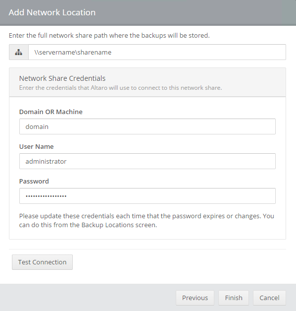
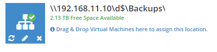
icon appears in your Backup Schedule tile indicating that an offsite copy is configured to run along with this schedule:

  • Lastly, Drag and drop the VM(s) from the left hand column over to the Schedule group you wish to add them to, then click Save Changes

Seeding

When backing up to an Altaro Offsite Server, it's likely that the bandwidth to that server may be limited, so we have introduced the option to manually take the first full backup to the Altaro Offsite Server physically, which will then allow you to run only incremental copies over the WAN connection, we call this process Seeding to disk.

The below diagram summarizes the Seeding process in 3 steps:
 

To do this, you will need a removable disk connected to your main Altaro VM Backup server.
Once done, Open the Management Console and go to Virtual Machines then to Take Offsite Copy on the left hand side menu.
 
Select the VMs you wish to transfer the backups for and click the Seed to Disk button at the top of the page as below:


Here, select the location you wish to seed to, and click Next as shown below:
 

The seeding will proceed in the background, and when complete you can disconnect the drive and manually take it to your Offsite Server.
 
Once the removable disk has been connected to your Altaro Offsite Server, launch the Altaro Offsite Server console from the Start Menu.
 
Here, go to Configure Accounts, then right click your account name and select Import seed from disk as shown below:


On the next screen, browse to the removable drive (and subfolder if applicable) where you exported the seed data to, select it and hit Start. 
 
It will begin to import the seed data to the Altaro Offsite Server's backup repository and show progress as below:
 

Once complete, any future backups to this Altaro Offsite Server will be of incremental changes only.
 

Setting up Console Remote Access to Altaro VM Backup

The introduction of the remote management console means that you can now install the software on another machine and manage the software from that remote machine. 
 
To access the Altaro VM Backup console remotely, you must install the Altaro Management tools 
 

Installing the Altaro Management Tools

To install the Remote management console on another machine, you must download and run the installer from here: http://www.altaro.com/vm-backup/download-tools.php
This is only supported on 64-bit OS's, please see the full system requirements here.
Once the Altaro Management Tools are installed, you will be able to launch the following consoles:
  • The Altaro VM Backup console - used to access the configuration and console of a remote Altaro VM Backup Installation
  • The Altaro Offsite Server console - used to access the configuration and console of a single remote Altaro Offsite Server

Using the Remote Management Console

The Remote Management Backup console will allow you to connect to the configuration console of a remotely installed Altaro VM Backup machine.
 
Please follow the instructions below for use:
  1. From the Start Menu launch Altaro VM Backup
  2. When the remote console is opened, you will be presented with a choice to connect to a local agent or a remote machine as below:


  1. Here you can select the second option to connect to a remote Altaro console and manage its configuration.
  2. Simply enter the servers IP and credentials and click Connect
Note: Ensure that the User Account you are using to connect with is a member of the Administrators Group
 

Using the Altaro Offsite Server Console

The Remote Offsite Server console will allow you to connect to the configuration console of a remotely installed Altaro Offsite Server.
 
Please follow the instructions below for use:
  1. From the Start Menu launch Altaro Offsite Server Management Console
  2. When the remote console is opened, you will be presented with a choice to connect to a local agent or a remote machine as below:


  1. Here you can select the second option to connect to a remote Altaro Offsite Server console and manage its configuration.
  2. Simply enter the servers IP, port and credentials and click Connect.

Using the Central Monitoring Console

The Central Monitoring Console will allow you to connect to multiple installations of Altaro VM Backup and get an at-a-glance look at their status.
 
Please follow the instructions below for use:
  1. From the Start Menu launch Altaro VM Backup
  2. When the console is opened, you will be presented with a choice to connect to a the Management console, or the Central Monitoring Console.
    Choose the second option and you will be taken to a screen similar to the below:


  1. Here you can click the Add Altaro VM Backup Instance to start monitoring a new Altaro VM backup installation.
  2. Enter the details and credentials for the installation you wish to start monitoring, as shown below:

  3. Simply enter the servers IP and credentials and click Save
  4. You will then be presented with a screen similar to the below, where you can monitor backups and status of multiple Altaro VM backup installations.


    You can also drill down using the Connect button to quickly connect and modify the configuration etc of each instance individually.
Note: Ensure that the User Account you are using to connect with is a member of the Administrators Group


    How to Setup VMware DRS – Distributed Resource Scheduler

    $
    0
    0

    The main reason you would want to set up a cluster in vSphere is to take advantage of the High Availability (HA) and Distributed Resource Scheduler (DRS) features. In this post, I’ll cover the benefits and functionality of VMware DRS and will briefly touch on how to set it up.


    What is DRS?

    Let’s begin by highlighting the benefits derived using DRS;

    Load Balancing – In a nutshell, DRS monitors resource utilization and availability on the constituent hosts of a cluster. Depending on how it’s configured, DRS will recommend or automatically migrate virtual machines from a host running low on resources to any that can sustain the additional load and supplement the resources required by the vms. The main function of DRS is thus to ensure that a vm is allocated the required compute resources for it to run optimally.

    Power Management – VMware Distributed Power Management (DPM) is a sub-component of DRS which essentially places one or more ESXi hosts in standby-by mode if the remaining hosts are found to be providing sufficiently excess capacity. When resources start running low, DPM will power back on hosts to keep capacity running at an optimum level.

    Virtual Machine Placement – Using DRS groups, affinity and anti-affinity rules, you can specify which virtual machines will reside on which hosts. You can also lock the placement of mutually dependent vms to a specific host for improved performance.

    Resource Pools– While resource pools are not exclusive to DRS since they can be created on any ESXi host, it is only after you enable DRS that you are able to create resource pools on those hosts which are members of a cluster.

    Storage DRS – This feature is independent of enabling DRS on an ESXi cluster but nevertheless I thought it’s best to give it a mention even though I won’t cover it in any detail. Put simply, if you have several datastores, you can group these under a datastore cluster for which you can optionally enable Storage DRS as shown in Figure 1. From there on, sDRS takes care of load balancing the disk space and I/O requirements for the virtual machines residing within that datastore cluster.


    Figure 1 – Turning on sDRS (using the C# vSphere Client)


    What are the requirements?

    Basic – You will need at least two ESXi hosts participating in a cluster managed by vCenter Server. Every ESXi host must be configured for vMotion. Each host will preferably be allocated a 1Gbit link on a private network reserved solely for vMotion traffic.

    Storage – A SAN or NAS based shared-storage solution allowing for the provision of iSCSI or NFS based datastores mounted on every ESXi hosts which is included in the cluster. Datastore naming should be consistent across all hosts.

    Processors – Preferably, all hosts should be sporting the same type of processor(s) to ensure correct vMotion transferring and state resumption. Once the vm is transferred, the processor(s) on the destination host should present the same processor instruction set and pick up executing instructions from where the source host processor(s) stopped. Enhanced vMotion Compatibility (EVC) should be enabled wherever dissimilar processors are used.


    Any gotchas?

    Software companies like Oracle and Microsoft require you to purchase a license for every host on which you plan to run products such as Microsoft SQL Server or Oracle Database. If you have large clusters, the price tag will quickly inflate. As you’ll see further on, you could use VM-Host affinity rules to make sure that such vms are “preferably” placed only on those hosts for which you acquired licenses. You could also opt to disable DRS altogether for the specific vms. While I’m not covering HA here, note that the same issue will arise when a host fails since the vms that were running on it are optionally restarted on another host, one that has not necessarily been licensed.

    Licensing is generally a complex and often obfuscated topic, so make sure to understand the requirements and repercussions before enabling DRS (and HA) for products burdened by restrictive licensing schemes. This will ensure that, come audit season, you’re not caught violating licensing agreements.


    How do I set it up?

    Enabling DRS couldn’t be simpler. Just right-click on the cluster name, select “Edit Settings” and turn it on (Figure 2). I’m using the traditional (c#) vSphere client (my bad) but you’ll be better off using the vSphere Web client as in general it exposes more settings for the particular feature you are enabling or managing.


    Figure 2 – Enabling DRS on a cluster (using the C# vSphere Client)

    Simply turning on DRS will suffice for most environments. However you need to be aware that the default automation level is set to “Fully Automated”. What this means is that DRS will automatically move vms across host whenever it deems it necessary. In fact there are 3 levels of automation. These are;
    Manual – when this mode is selected, DRS will suggest whether vms are to be migrated or not if resources are running low. All subsequent actions require user-intervention. As can be seen in Figure 3, DRS keeps on prompting until you tell it which host you want your vm powered up on.


    Figure 3 – Selecting the host on which a vm is powered up

    Partially Automated – in this mode, DRS will automatically place a vm that’s just been powered up on a host with optimal capacity. During the course of normal operations, DRS will make suggestions about those vms that need migrating. To view them, click on the cluster name and select the DRS tab while in “Hosts and Clusters” view when using the vSphere client. Clicking the “Apply Recommendations” button actuates these recommendations with the respective vms being migrated to the DRS chosen hosts. Suggestions are also made when running DRS in manual mode. DRS does a check every 5 minutes but you can force it to run by clicking on “Run DRS” as shown in Figure 4 highlighted in red.

    Figure 4 – Manually running DRS


    Fully Automated – as the name implies, DRS will take care of automatically moving vms whenever the need arises.
    This automation level is shown in Figure 5. One should be careful of the “Migration Threshold” setting at the bottom which, if set too high, may result in an inordinate number of migration especially in large environments. This may result in performance issues specifically on the storage and network fronts due to an increase in the demand for iops and bandwidth.


    Figure 5 – Setting the migration threshold

    The automation level can also be individually set for each vm. Doing so, overrides the cluster settings.


    Figure 6 – Overriding cluster enforced settings


    DRS Groups and Rules

    There are instances where you’d want a particular set of virtual machines to run on the same host or group of hosts. There will be other times where you definitely want to have two or more vms running on separate hosts to minimize performance issues perhaps to isolate a heavily used database vm from an equally utilized mail server. DRS provides for this as follows;

    VM-VM Affinity Rules

    Keep vms together (Affinity) – use these to have a group 2 or more vms run on the same host
    Separate vms (Anti-Affinity) – use these to have a group of 2 or more vms run on separate hosts

    Note: If any two rules conflict, the older one is left enabled while the most recent is disabled. You can however select which rule to enable. In the following example I set up two rules. The first specifies that vm a and vm b should be kept together. The second, on the contrary, specifies that the two vm should be kept apart thus resulting in a conflict with the first rule. A red icon next to the rule will alert you of existing conflicts (Figure 7).


    Figure 7 – Conflicting rules

    VM-Host Affinity Rules

    Virtual machines to hosts – Bind one or more vms to a pre-defined DRS group of hosts
    Note: No rule checking is performed for VM-Host affinity rules so you may end up with conflicting rules. Again, the older rule takes precedence with the new one being automatically disabled. Care should also be exercise when creating this type of rule since any action violating a required affinity rule may prevent;
    • DRS from evacuating vms when a host is placed in maintenance mode.
    • DRS from placing virtual machines for power-on or load balance virtual machines.
    • HA from performing failovers.
    • DPM from placing hosts into standby mode.
    Consult the following guide (specifically 83-86) for further details.
    DRS Groups and Rules can be set from the Cluster settings shown below. You only need to create groups when setting up “Virtual machines to hosts rules” since the option is not available when creating affinity and anti-affinity rules (See Figures 8 and 9).


    Figure 8 – Setting up VM and Host DRS groups


    Figure 9 – Creating vm rules

    Pay particular attention when creating “Virtual Machines to Hosts” rules. You are given four options (see Figure 10 – options boxed in green) to choose from and although similarly worded, the behavior is anything but similar.

    Be wary of using rules starting with “must” as this implies strict imposition. In practical terms, let’s say you create a “must run on hosts in group” rule for a particular vm. If for any reason the hosts in the referenced group are offline, the vm will not migrate and/or is prevented from powering up – unless of course you disable or delete the rule. This can also lead to a host affinity rule violations as a result of any of the unwanted scenarios previously mentioned. If this happens, disable the offending rule and manually run DRS (or wait for it to do so automatically, the interval being every 5 minutes). Any stuck process, such as placing a host in maintenance, should resume normally after a short while.

    Unless absolutely necessary, avoid using “must” and opt instead for “should”. This simply sets a preference with regard to which host to use. If none are available, DRS selects the next best option.


    Figure 10 – Specifying the rule type


    Monitoring DRS

    If you switch to the Summary tab, you should see a “vSphere DRS” information pane on the upper-right part of the screen (Figure 11). Here you are presented with DRS related information including the automation level set, the number of outstanding recommendations and the degree to which the cluster is load balanced. There’s also a link to the “Resource Distribution Chart” which when clicked on opens up a window showing the load distribution across the cluster using  CPU and Memory utilization per host as a metric (Figure 12).

    Figure 11 – DRS status window


    Figure 12 – DRS Resource Distribution chart


    Disabling DRS

    If for any reason you find yourself needing to disable DRS, you will need to keep a couple of things in mind. The first is that you WILL LOSE any existing Resource Pool hierarchy, including vm membership (I learned this the hard way!).

    One a more positive note, the vSphere Web client allows you to save the resource pool tree for future import which is perhaps one more reason why you should consider ditching the old client. However, note that while this process will restore your original resource pool structure IT WILL NOT restore vm membership, meaning you’re left with a bunch of empty resource pools. In addition, you will not be able to re-import the resource pool tree if you created new resource pools after you re-enabled DRS. To be honest I don’t see this as being of any use but as they say we should always be thankful for small mercies.


    Figure 13- Disabling DRS / Resource Pool removal warning

    The second, is that any rules set up prior to disabling DRS will still apply. If fact if you re-enable DRS, any previously set rules will magically reappear. According to this article, one should be wary of “should” rules when DRS is disabled which apparently do not work as expected. I tried replicating this on a vCenter Server 6.0 / ESXi 6.0 environment (2 nested node cluster) and the behavior of “should” rules remained the same irrespective of DRS being enabled or not.


    Conclusion

    I think I’ve covered most of what there is to cover on the subject. I haven’t really explored DPM as I don’t have the resources on which to test and to be honest even when I did, I never really bothered setting it up not because I didn’t want to but simply because the companies I worked for never really took that much of an environmental friendly approach to virtualization. I’ll be covering High-Availability soon which to a lesser extent is tied to DRS.


    How to Configure VMware High Availability on a vSphere Cluster

    $
    0
    0

    In a recent article, I described VMware’s DRS and how it complements another cluster centric feature, VMware High Availability (HA), the subject of today’s post. The primary purpose of HA is to restart virtual machines on a healthy host, should the one they reside on suddenly fail. HA will also monitor virtual machines at the guest’s operating system and application level by polling heartbeats generated by the VMware Tools agent installed on monitored vms.


    Better still, enabling HA on your cluster unlocks Fault-Tolerance (FT) the functionality of which has been greatly beefed up in vSphere 6, effectively making it a viable inclusion in any business continuity plan.  Having said that, FT is somewhat stringent on the requirements side of things making its adoption a tough sell for SMEs and similar. Another thing to keep in mind is that FT will only offer protection at the host level. If application level protection is what you’re after, then you’d be better off using something like MSCS. I’ll cover this in more detail in an upcoming article on FT.

    At this point I feel that I should also clarify that contrary to popular belief, HA does not provide or guarantee a 100% uptime or anything close for that matter. The only one certainty is that when a host hits the dust, so will the vms residing on it. There will be downtime. If set up correctly, HA will spawn said vms elsewhere in your cluster after approximately 30 seconds. While 100% uptime is an impossible ideal to achieve, HA coupled with FT are both options you should be considering if improving uptime metrics is your goal.

    For demonstrational purposes, I’ll be using a vSphere 6.0 two-node HA enabled cluster. Keep in mind that you’ll also need to have ESXi hosts access the same shared-storage on which the virtual machine files reside. Have a look here for a complete checklist of HA pre-requisites.


    How does HA work?

    When HA is enabled, a couple of things occur. Firstly, an HA agent is installed on each host in the cluster after which they start communicating with one another. Secondly, an election process (Figure 1) selects a host from the cluster to be the Master, chosen using criteria such as the total number of mounted datastores. Once a Master is elected, the remaining hosts are designated as slaves. Should the Master go offline, a new election takes place and a new Master is elected.

    Figure 1 – HA election in progress


    The main task of the Master is to periodically poll vCenter Server, pulling state information for the slave hosts and protected virtual machines. If a host failure occurs, the Master uses network and datastore heartbeating to verify that a slave has in fact failed. This 2-factor monitoring method ascertains that a slave has really failed and not simply ended up being partitioned (unreachable but still exchanging datastore heartbeats) or isolated (slave fails to contact other HA agents and network isolation address).

    It is important that you select at least two datastores (Figure 2) when setting up “Datastore heartbeating” from “vSphere HA”. You’d still be able to set up HA using only one datastore but for added redundancy VMware suggest that you specify a minimum of two datastores. You should also note that you cannot include VSAN datastores.


    Figure 2 – Selecting datastores for host monitoring

    How do I enable it?

    Well, as with most other features, enabling HA on a cluster is a piece of cake! If you’re using vSphere client, change the view to “Hosts and Clusters”, right-click on the cluster name, select “Cluster Features” and click on the “Turn On vSphere HA” check-box (Figure 3). Next, select “vSphere HA” and make sure that the “Enable Host Monitoring” check-box is selected (Figure 4). Click OK and you’re done.


    Figure 3 – Turning on HA for a cluster (using the C# vSphere Client)


    Figure 4 – Enabling Host monitoring (using the C# vSphere Client)

    If instead you’re using vSphere Web client, you’ll need to navigate to “Clusters” and highlight the cluster name in the Navigator pane. In the right pane, switch to the “Settings” tab, highlight “vSphere HA” and click the Edit button. Click on the “Turn on vSphere HA” to enable HA for the cluster. Similarly, you’ll see that the “Host Monitoring” option is enabled by default (Figures 5-6).

    Figure 5 – Turning on HA and Host monitoring on a cluster (using the vSphere Web Client)


    Figure 6 – Turning on HA and Host monitoring on a cluster (using the vSphere Web Client)

    By simply enabling HA and sticking to the default settings, you are guaranteed that in the event of a host failure, the virtual machines on a failed host are automatically powered up elsewhere.

    Fine-Tuning HA

    There are three types of failure scenarios these being Failure, Host Isolation and Cluster Partitioning. In all instances, virtual machine behavior can be managed accordingly.

    Host monitoring

    Host monitoring is turned on and off by clicking the “Enable Host Monitoring” check box under “vSphere HA” (Figure 4 above). It is important that you unselect the setting whenever you carry our network maintenance to avoid false isolation responses.

    Host failure can result from a number of issues including hardware or power failure, network changes planned or otherwise and even a crashed ESXi instance (PSOD). A complete failure is deemed such whenever a host cannot be reached over any of the environment’s network and storage paths. When this happens, the Master performs an ICMP test over the management network. If the suspect host does not respond, the Master will check for any signs of datastore activity from the host’s part. When both monitoring methods fail, any vms running on the failed host are assumed dead and restarted on any of the alternative hosts in the cluster.

    Admission control

    Admission control is the process by which HA monitors and manages spare resource capacity in a cluster.
    The default “Admission Control” setting found under “vSphere HA” is set to ignore availability constraints. In other words, HA will try to power on vms regardless of capacity. This is generally not a good idea and you should follow the best practices for admission control listed here. For instance, since I only have 2 nodes in my cluster, I set the number of “Host failures the cluster tolerates” to 1. Setting in to 2, will result in the following warning (Figure 7), something to be expected.

    Figure 7- HA insufficient resources warning


    Alternatively, you can set aside a percentage of CPU and Memory cluster resource as spare capacity for fail-over purposes or simply specify which hosts are designated for fail-over (Figure 8).


    Figure 8 – Configuring HA Admission Control

    VM Behavior

    You can control the behavior of virtual machines by modifying the settings under “vSphere HA -> Virtual Machines Options” as shown in Figure 9. The “VM restart priority” level determines the order by which resources are allocated to a vm once it is restarted on an alternate host. The “Host Isolation response” setting on the other hand, specifies what happens to a virtual machine once a host becomes isolated. The settings enforced by the cluster-wide policy can be overridden on a per vm basis. In the example shown below, I’ve disabled “VM Restart Priority” for Win2008-C. In this case, the vm remains where it is if and when its parent host fails. Similarly, if the host is isolated, Win2008-C will shut down instead of keeping on running as specified by the cluster policy.

    Figure 9 – Setting virtual machines options


    VM Monitoring

    HA monitors virtual machines at the OS and at the application level provided the application being monitored supports VMware Application Monitoring or has been modified via an SDK to generate customized heartbeats. In both cases, HA will restart the vm if it is no longer receiving heartbeats from it. HA will also monitor a vm’s disk I/O activity before rebooting it. If no disk activity has been observed during the “Failure Interval” period (Figure 10), HA will reboot the vm.

    After the vm reboots, HA will wait a “minimum uptime” number of seconds before it resumes monitoring to allow enough time ffor the OS and vmtools to properly initialize and resume normal operations. Failing this the, the vm may end up being rebooted needlessly. As an added precaution, the “Maximum per-VM resets” limits the number of successive reboots withing a time frame governed by the “Maximum resets time window” setting. As per previous settings, both VM and Application monitoring can be set on an individual basis by ticking on the “Custom” checkbox next to the “Monitoring sensitivity” slider.

    The default settings are as follows:

    Failure Interval (seconds)Minimum Uptime (seconds)Maximum per-VM resetsMaximum resets time window
    Low12048037 days
    Medium60240324 hours
    High3012031 hr


    Figure 10 – Setting vm monitoring options

    VM Component Protection

    When a host fails to contact any other agents running in the cluster, it tries to reach what is called a network isolation address which by default is set to the default gateway configured on the host. If the latter fails as well the host declares itself isolated. When this happens, the Master keeps monitoring vms on the isolated host and will restart them if it observes that they are being powered off. Sometimes though very rarely, a situation called split-brain may arise where two instances of the same vm are both online. Even so, one instance only will have read and write access to the vmdk files.

    This scenario occurs when the Master, using datastore heartbeats, fails to determine whether a host is isolated or partitioned and consequently powers up the same vms on another host. To prevent this from happening, use the vSphere Web Client and enable VM Component Protection as shown in Figure 11. Further details on how to set this is up are available here on pgs. 19-20.

    Figure 11 – Configuring PDL and APD settings using the vSphere Web Client


    Monitoring HA

    When you select the cluster name in vSphere Client and switch to the summary tab, you should see a “vSphere HA” information window displaying some HA metric and status in accordance with the settings you specified. In addition there are 2 links at the bottom of the window named “Cluster Status” and “Configuration Issues” respectively. Clicking them provides some further details about the HA status and setup (Figure 13-15).

                                                           Figure 12 – HA metrics and status window


    Figure 13 – HA Host operation status


    Figure 14 – HA vm protection status
    Figure 15 – HA designated datastores


    Conclusions

    I hopefully covered most of the important stuff you need to know about HA. When enabling HA and DRS on the same cluster, which you’ll probably do, you will need to keep track of any affinity rules you might have set up and how these might conflict with HA settings. Ideally you should test any change you plan on introducing prior to going live with it.

    The last thing you’d want is to have vms power off or reboot unexpectedly in the middle of the night. Host monitoring on its own is a great thing to have as it provides yet another layer of high availability to your infrastructure. VM and application monitoring overlays another layer of protection but for reasons already mentioned be sure to tread carefully before implementing VM / App monitoring all across the board.

    How to Setup VMware Fault Tolerance in vSphere 6.0

    $
    0
    0


    In this post we will shows you how to turn FT ON and OFF. I’m using a 2-node cluster supporting nested hypervisors so performance is what it is.

    Fault Tolerance is a seldom used feature that has been available since the days of VMware Infrastructure, the old name for what we today know as VMware vSphere, the software suite comprising vCenter Server and the ESXi hypervisor along with the various APIs, tools, and clients that come included with it. If you’ve been through my post on High Availability, you’ll probably know that Fault Tolerance is a feature intrinsic to a HA enabled cluster.


    A brief overview

    VMware Fault Tolerance (FT) is a process by which a virtual machine, called the primary vm, replicates changes to a secondary vm created on a host other than where the primary vm resides. Think mirroring. Should the primary vm host fail, the secondary immediately takes over with zero interruption and downtime. Similarly, if the secondary vm’s host goes offline, the secondary vm is re-created on another host, assuming one is available. For this reason, it’s best to have as a minimum a 3-node cluster even though FT works just as well on a 2-node cluster


    Figure 1 – FT architecture (Source: www.vmware.com)
    The one benefit that immediately stands out is that Fault Tolerance raises the High Availability bar a notch higher as it bolsters business continuity by mitigating against data loss and application downtime, something that the HA cluster feature alone cannot deliver. FT is also used in scenarios where expensive clustering solutions are impractical to implement from both technical and financial perspectives.

    Occasionally, you may come across the term On-Demand Fault Tolerance. Since FT is a somewhat resource expensive process, you may decide to employ scripting, just to mention one way of doing it, to enable and disable FT on a schedule. On-Demand FT is used to protect business critical vms and the corresponding business processes such as payroll applications and payroll runs against data loss and service interruption. That said, keep in mind that FT protects at the host level. It does not provide any application level protection meaning that manual intervention will still be required if a vm experiences OS and/or application failures.


    New features and support

    I used the word seldom in the opening line in reference to how FT has been generally overlooked, prior to vSphere 6 at least, mainly due to its lack of support for symmetric multiprocessing and anything sporting more that 1GB of RAM. In fact, before vSphere 6.0 came along, FT could only be enabled on vms with a single vCPU and 1GB of RAM or less which needless to say turned out to be a show stopper given today’s operating systems and application generous compute resource requirements.

    So, without further ado, the goodies vSphere 6.0 brings to FT are as follows. These are the ones which in my opinion make it a viable inclusion to any business continuity plan.
    • Support for symmetric multiprocessor vms
      • Max. 4 vCPUs (vSphere Standard and Enterprise licenses)
      • Max. 2 vCPUs (vSphere Enterprise Plus licenses)
      Note that FT is not available for vSphere Essentials and Essentials Plus licensed deployments.
    • Support for all types of vm disk provisioning
      • Thick Provision Lazy Zeroed
      • Thick Provision Eager Zeroed
      • Thin Provision
    • FT vms can now be backed up using VAPD disk-only snapshots
    • Support for vms with up to 64GB of RAM and vmdk sizes of up to 2TB
    And here’s a list of features both vm and vSphere centric that are still not supported
    • CD-ROM or floppy virtual devices backed by a physical or remote device.
    • USB, Sound devices and 3D enabled Video devices
    • Hot-plugging devices, I/O filters, Serial or parallel ports and NIC pass-through
    • N_Port ID Virtualization (NPIV)
    • Virtual Machine Communication Interface (VMCI)
    • Virtual EFI (Extensible Firmware Interface) firmware
    • Physical Raw Disk mappings (RDM)
    • VM snapshots (remove them before enabling FT on a VM)
    • Linked Clones
    • Storage vMotion (moving to an alternate datastore)
    • Storage-based policy management
    • Virtual SAN
    • Virtual Volume Datastores
    • VM Component Protection (see my HA post)


    Legacy FT

    Before I move on, I need to highlight that VMware now uses the term “Legacy FT” to refer to FT implementations pre-dating vSphere 6.0. If required, you can still enable “Legacy FT” by adding vm.uselegacyft to the list of advanced configuration parameters.


    Figure 2 – Enabling Legacy FT


    Cluster and Host basic requirements

    One in particular, namely a 10 Gbit dedicated network, is a bit stringent in that you’d generally find this kind of infrastructure deployed in large enterprises so FT may be a hard sell for SMEs and the likes. Other than that, just ensure that the host CPUs in your cluster support Hardware MMU virtualization and are vMotion ready. For Intel CPUs anything from Sandy Bridge upwards is supported. For AMD, Bulldozer is the minimum supported microarchitecture.

    On the networking side, you’ll need to configure at least one vmkernel for Fault Tolerance Logging. At a minimum, each host should have a Gbit nic dedicated to vMotioning and another to FT Logging.


    Figure 3 – Setting up a vmkernel for FT logging
    Note: For DRS to work with FT, you will need to enable EVC. Apart from ensuring a consistent CPU profile, this allows DRS to optimize the initial placement of FT protected vms.


    Turning FT on and off

    There are a number of requirements to fulfill before you can turn on FT for a vm. You’ll need to ensure that the vm resides on shared storage (iSCSI, NFS,etc) and that is has no unsupported devices (see list above). Also note that the disk provisioning type changes to “Thick Provision Eager Zeroed” when FT is turned on. This may take a while for large sized vmdks.

    FT can be turned on irrespective of the vm being powered on or not. There are also a number of validation checks, which  depending on whether the vm is running or not, will slightly differ.

    To turn on FT, just right-click on the vm and select “Turn On Fault Tolerance”. Use the same procedure to turn it off.


    Figure 4 – Turning on FT on a virtual machine


    Figure 5 – Changes affected on a vm once FT is turned on
    Turning-On-Off
    If the vm passes the validation checks, you should find that the secondary vm is created on a different host other than that of the primary. In this case I’ve enabled FT on a vm called Win2008-C which is hosted on 192.168.11.63. The secondary vm Win2008-c (secondary), as you can see, is created on 192.168.11.64.Figure 6 – vmdk scrubbing – changing provisioning type to thick eager zeroed


    Figure 7 – Primary VM’s host


    Figure 8 – Secondary VM’s host
    Now select the vm for which you turned on FT. Under the “Summary” tab you should see a sub-window titled “Fault Tolerance”. A number of FT metrics for the specific vm are displayed here. Of particular interest is the “vLockstep interval” which simply put is a measure of how far behind the secondary vm is from the primary in terms of replication changes.

    Typically the value should be less than 500ms. In the example shown below the interval stands at 0.023s or 23ms which is good. Another metric is “Log Bandwidth” which is the network capacity currently in use to replicate changes from the primary to the secondary vm. This can quickly increase when you have multiple (max. 4 vms or 8 vCPUS per host) FT protected vms hence the 10Gbit dedicated network requirement for FT logging.

    Figure 9 – Fault Tolerance details for a FT protect virtual machine

    You can simulate a host failure by selecting “Test Failover” from the vm’s context menu. Similarly, a simulated Secondary restart is carried out using the same menu. In both instances, the vm is momentarily left unprotected until the test completes.


    Figure 10 – Testing failover
    The next video shows you how to test a failover and perform a secondary restart. It doesn’t need much explaining but for completeness sake I’ll give a brief run through. As per the previous video, I’m using a 2-node nested environment with FT already enabled on the vm called Win2008-C.
    FT-Testing-FailOver-Secondary
    • I first illustrate where from HA (and DRS) is enabled so that FT, in turn, can be enabled.
    • Next we verify that the primary and secondary vms are hosted on separate servers.
    • We then initiate a failover test while  pinging the FT protected vm’s ip address. Normally you would experience a single “ping” loss but given the low resource environment I’m using, you’ll notice a loss of 3 packets. After a brief while, the secondary vm powers up and takes over from where the primary failed.
    • Next, we simulate a secondary restart. This time there’s only one single packet loss. Notice that the vm is briefly left “unprotected” following which it returns to being fully protected as expected.


    Conclusion

    Undoubtedly, vSphere 6.0 and the improvements it brought about to Fault Tolerance should make it a very valid tool to have towards ensuring business continuity and why not, fewer calls in the middle of the night. The 10Gbit dedicated network may prove too much of a requirement for small businesses. That said, you could always settle for cheaper 10Gbit gear but then again if you’re using FT to protect mission critical machines I think it’s best to go the extra mile and work with trusted providers.

    That’s if for FT. For a complete list of requirements and functionality do have a look at these;


    How to Setup VMware vApp in vCenter Server in 4 steps

    $
    0
    0

    Before jumping in to show you how to create and setup a vApp in vCenter Server, I just need to outline the prerequisites, these being a vCenter Server managing a DRS enabled cluster or any standalone host running ESXi 4.0 or higher.


    VMware vApps are perhaps one of the most underutilized features of vCenter Server. A vApp is an application container, like a resource pool if you will but not quite, containing one or more virtual machines. Similarly to a vm, a vApp can be powered on or off, suspended and even cloned.
    The feature I like best is the ability to have virtual machines power up (or shut down) in a sequential fashion using one single mouse click or command. Suppose you have a virtualized Microsoft-centric environment comprising a file server, a DNS server, a couple of AD domain controllers and an Exchange Server. VMware refers to such environments as multi-tiered applications.

    Normally you would switch on the DNS server first, followed by the domain controllers, the file server and finally the Exchange server. The reverse sequence holds true when it comes to powering down the entire environment perhaps due to scheduled maintenance. A vApp allows you to group all these components under one logical container. Better still, you can specify the vm start up order and the time taken in between powering up or shutting down the next vm.


    Figure 1 – DRS enabled cluster in vCenter Server


    Step 1: How to Create a vApp

    Creating a vApp is the proverbial piece of cake. You can use both the vSphere traditional and Web clients (Figures 2-3), or if you’re so inclined, PowerCLI. After signing in to your vCenter Server, do the following;
    • Change the view to “Host and Clusters”, right-click on the cluster object and select “New vApp”.

    Figure 2 – Creating a vApp using the vSphere Web client


    Figure 3 – Creating a vApp using the traditional vSphere client

    • Specify a name for the vApp, select a data centre and click Next.

    • Allocate the required resources and click Next. As a side note, these are the same resource allocation settings you would set for resource pools so take care when applying them.

    • Press Finish to finalize the creation of the vApp.

    Step 2: Configuring a vApp

    Once you’ve created your vApp container, you can proceed to move the vms to it. Going back to the virtualized Microsoft environment example, I’ll first move a set of virtual machines to the vApp. Next, I’ll configure the “Start Order” of the VMs inside it. The process is best illustrated by means of a video so here it goes.


    As you’ve seen in the video and as shown in Figure 4, a group is by default created for every vm. Each group can hold multiple vms but be aware that multiple vms residing under the same group will switch on or off concurrently regardless of time intervals set. To overcome this limitation, you simply place each vm in its own dedicated group. Note that for demonstration purposes, I’ve set the time interval to 5s (Figure 4). 

    The default setting is of 120 seconds but generally you’ll need to experiment until you strike the correct balance which depends on the type of environments and multi-tier applications deployed as well as the performance of the overall infrastructure. The “VMware Tools are ready” option basically tells the vApp to wait until VMware Tools are running on the current vm before moving on to power up the next one in the chain. This is a great option to go by assuming VMware Tools are installed and running correctly.


    Figure 4 – vApp start order

    Alternatively, you can nest vApps. That’s right. You can create one or more vApps each with its own configuration. This provides you with a more granular approach based on system type. For instance, you’d be able to shut down the vApp containing the Exchange servers without affecting anything else under the parent vApp. Figure 5 illustrates a nested model with children vApps created for Domain Controllers and Exchange servers both of which residing under a common parent vApp.


    Figure 5 – Nested vApps


    Step 3: More vApp settings

    Under the vApp settings you’ll see 3 tabs: Options, Start Order (which we’ve already covered) and vServices. The latter provides no value at all since the only service extension available is the one for vCenter. Moreover, this can only be bound to virtual machines so I’m not entirely sure why it is presented as an option.


    You’ll find 4 categories under the Options tab, these being Resources (we’ve covered this as well), Properties (not applicable in this context), IP Allocation Policy and Advanced.
    The IP Allocation Policy allows you to specify how network information is applied to the vms residing under the vApp. Fixed and DHCP are self-explanatory. The first simply means that vms will have statically assigned network settings. The second implies that the network settings are applied using a DHCP server.


    The Transient option is a little bit more involving since you’ll need to create an IP Pool at the datacenter level and tie it to the network(s) your vApp vms are configured for. In the example below, I created a /24 network with 20 IP addresses in the range 10.0.0.11-30. Once the IP pool is set, the vms in the vApp will acquire an IP address from this pool which is released only when the vApp is powered off.


    Step 4: Exporting, importing and cloning vApps

    OVF is the default distribution format for vApps and consequently a vApp can be exported to as such. Exporting vApps is a great feature to have as it allows you to backup an entire environment to a single file which you can re-import at any time to the original hosting vCenter Server or an alternative one. Cloning is supported as well, the only caveat being that the vApp must be powered off before it can be cloned. The next video illustrates how a vApp is imported and exported to and from vCenter Server.

    vApp-import-export
    Cloning a vApp is just a matter of right-clicking on it and selecting “Clone”. Alternatively, you may wish to use PowerCli as follows (change the items in red accordingly);
    New-VApp -name ‘AD Environment 2’ -Location (get-cluster ‘Cluster’) -VApp (get-vapp ‘AD Environment’) -Datastore ‘iSCSI LUN A’


    Some additional PowerCLI cmdlets you’ll surely find handy are;


    Conclusion

    As we have seen, vApps can be a great addition to one’s arsenal of VMware tricks. You’ll find vApps to be extremely handy in disaster recovery scenarios where you would want to automate and quickly power up mutually dependent virtual machines using a single click or command. vApps also lend themselves extremely well to any backup strategy by providing the means to quickly back up and restore multi-tiered applications or environments using a single OVF package, assuming they are static workloads. 

    This in turn can be backed up or archived as part of a disaster recovery plan. When disaster strikes – touching wood! – the backed up OVF is restored to a make-shift or replacement vSphere infrastructure to quickly bring online any essential services you might need. Compare this to having to restore and power up each and every constituent virtual machine one at a time. Now, couple this with the fact that it only takes a few mouse clicks to create and configure a vApp and I think you’ll agree that vApps are too much of a good feature to overlook.


    How to Setup VSAN using an ESXi 6 Nested Environment

    $
    0
    0

    In this article we will show you how to setup vSAN using an ESXi nested environment. Before we dive into the nitty gritty of setting up VSAN, I’d first like to give a brief introduction of what VSAN is all about.

    VSAN which is short for VMware Virtual SAN, has been with us since March 2014. It’s VMware’s take on hyper-convergence or the abstraction of storage from the underlying hardware while providing a single pane of glass (the vSphere client) to manage storage alongside your virtualized resources. VMware achieve this through
    vSAN by pooling unassigned local drives on a number of ESXi hosts which it then presents as one single datastore. If that isn’t neat I don’t know what is!

    In practical terms, what this means is that you now have the option of choosing between an often complicated and expensive networked storage solution – think SAN, NAS and all the hybrids in between – and a one stop shop for all your storage, compute and virtualization needs.


    Nested Virtualization

    In this tutorial, I’ll be using a nested environment. I’ll briefly explain what nested virtualization is, just in case this is all new to you. Simply put, we’re talking about virtualizing hypervisors, implying that one or more hypervisors are running as virtual machines which in turn are hosted on a hypervisor running on a physical machine.

    At a high level you have one or more physical servers running ESXi. We call these level 0 (L0) hypervisors. This is represented in Figure 1 namely by the physical ESXi server having IP address 192.168.0.1.

    One or more virtual machines are created on the L0 hypervisor. These will act as the receptacles for our virtualized ESXi servers. We call these our level 1 (L1) guest hypervisors labelled L1 in Figure 1.
    Any virtual machine created on an L1 hypervisor is referred to as level 2 (L2) guest.


    Nested-Hypervisors
    Figure 1 – Nested Hypervisors

    In theory you can keep going on but I cannot really justify any real-world use case, so time to move on. It is important to stress that this is an unsupported feature as far as VMware is concerned and is subject to a number of requirements in order to make it all work. The moral of this story is “do not use this for your production environments“.

    So why should I bother, I hear you ask? Well, if you lack the financial resources, which generally translates to less hardware to play with, you will find that nested virtualization provides an excellent alternative for say setting up a home lab. Likewise, you can cheaply set up test environments for QA and Testing purposes which are relatively easy to set up and can be quickly disposed of and rebuilt from scratch.


    The Testing Environment

    My setup consists of a 3 node cluster comprising ESXi 6.0 U1 nested servers managed by a virtualized vCenter 6.0 server. Figure 2 shows the virtual machines created on a physical ESXi 5.5 server (L0).


    Figure 2 - Nested HypervisorsFigure 2 – Nested Hypervisors

    Once vCenter is installed, we can connect to it and create a cluster to which we add the 3 nested ESXi servers. This is illustrated in Figure 3.


    Figure 3 - 3-node ESXi Cluster
    Figure 3 – 3-node ESXi Cluster


    VSAN Requirements

    As per VMware’s VSAN requirements a cluster must contain a minimum of 3 ESXi hosts each having at least one SSD drive for caching. For every ESXi host, I applied the settings shown in Figure 4.

    Figure 4 - VSAN ESXi Host Requirements
    Figure 4 – VSAN ESXi Host Requirements

    There’s a nifty trick you can use to emulate an SSD hard drive when creating a virtual machine. We do this by adding the line scsi0:1.virtualSSD = “1” to the “Configuration Parameters” list for the vm in question. In the example below, I’ve set the 2nd drive on controller 0 (0:1) to be of type SSD.

    Figure 5 - Emulating an SSD driveFigure 5 – Emulating an SSD drive Each host has a total of 3 drives, one for the ESXi OS, a second for caching and a third one acting as a repository for the virtual machines we eventually deploy. The hard drive capacities I chose are all arbitrary and should by no means be used for production environments.


    Enabling VSAN

    There is one final setting that needs doing on every ESXi host before we can provision VSAN. Basically we must allow virtual SAN traffic to pass over an existing or newly created VMkernel adapter.

    To do so, connect to the vCenter server managing the cluster using the vSphere Web Client (Figure 6).
    Once signed in, select each ESXi host one at a time and configure a VMkernel adapter. In the right-hand pane, navigate to the “Manage” tab and click on “Networking”. Click on “VMkernel adapters” and edit an existing VMkernel. You may wish to create a new one. Either way, make sure you tick on the ““Virtual SAN traffic” option (Figure 7).

    Figure 6 - VMkernel settingsFigure 6 – VMkernel settings

    Figure 7 - Allowing VSAN traffic throughFigure 7 – Allowing VSAN traffic through


    It’s important to emphasize that for production environments you will want to dedicate a VMkernel adapter for VSAN traffic. At the very least, each host should have a dedicated 1-Gbit NIC set aside for VSAN. VSAN also requires a private 1-Gbit network preferably 10-Gbit as per VMware’s best practices. However for testing purposes, our environment will work just fine.

    Now that we have all of our ESXi hosts set up we can proceed and enable VSAN. Surprisingly, this is as easy as ticking a single check box.

    Note: If enabled, vSphere DRS and HA must be turned off on the cluster before VSAN can be provisioned. DRS and HA can be turned back on once VSAN provisioning completes.
    Without further ado, let’s enable VSAN.

    Locate the cluster name from the Navigator pane using the vSphere Web client. Click on the cluster name and navigate to the “Manage” tab.  Under “Settings”, select “General” under the “Virtual SAN” options. Click on the “Edit” button as shown in Figure 8.

    Figure 8 - Provisioning VSANFigure 8 – Provisioning VSAN


    Tick on the “Turn ON Virtual SAN” check box. The “Add disks to storage” can be left to “Automatic” as per default setting but in a production environment you will probably select which unassigned disks are added to the VSAN datastore (Figure 9).

    Figure 9 - Turning on VSAN (at last!)
    Figure 9 – Turning on VSAN (at last!)

    Assuming that all the requirements have been met, the provisioning process will start. Shortly afterwards, you should find a newly created  datastore called vsanDatatore (Figure 10).

    Figure 10 - VSAN datastoreFigure 10 – VSAN datastore
    When you’re finished setting up VSAN, you simply turn back on DRS and HA for the cluster and you’re done.


    I’ve also included a 6 step video outlining the VSAN provisioning process I just reviewed.


    1. Check that “Virtual SAN Traffic” is enabled on a VMkernel on each ESXi host
    2. Turn ON Virtual SAN
    3. Verify that the vsanDatastore has been created
    4. Re-enable DRS and HA on the cluster
    5. Migrate a vm to the new VSAN datastore
    6. Browse the VSAN datastore and locate the folder of the vm just migrated
    P.S.: Once you enable VSAN, you will also want to review your Storage Policies, which I’ll probably cover in a future pos

    PanGu Jailbreak for iOS 9.1 released, compatible with all 64bit devices

    $
    0
    0

    I have some great news for jailbreakers who are still on iOS 9.1. The PanGu Jailbreak team has just released a new version of their tool to jailbreak iOS 9.1, making it the first jailbreak for iPad Pro, which was launched late last year.


    Apple had patched two vulnerabilities used in the Pangu iOS 9 Jailbreak in iOS 9.1 in October, so it has been a very long wait for the jailbreak community.

    According to Pangu’s website, the untethered iOS 9.1 jailbreak works only on 64-bit devices such as:
    • iPhone 6s Plus, iPhone 6s, iPhone 6 Plus, iPhone 6, iPhone 5s
    • iPad Air 2, iPad Air, iPad mini 4, iPad mini 3, iPad mini 2, iPad Pro
    So it is not compatible with the following devices currently:
    • iPhone 5, iPhone 5c
    • iPod touch 5G
    • iPad mini, iPad 2, iPad 3, iPad 4
    PanGu jailbreak for iOS 9.1 is available for both Mac and Windows. You can download Pangu jailbreak for iOS 9 – iOS 9.1 from our download page.

    Download Pangu Jailbreak
    Check out our step-by-step guide on how to jailbreak iOS 9 – iOS 9.0.2 along with a video tutorial if you need help, we expect it to work for the Pangu iOS 9.1 jailbreak as well.

    Download Pangu Jailbreak for iOS 9 – iOS 9.1:

    The untethered Pangu Jailbreak for iOS 9.1 works only on 64-bit devices such as:
    • iPhone 6s Plus, iPhone 6s, iPhone 6 Plus, iPhone 6, iPhone 5s
    • iPad Air 2, iPad Air, iPad mini 4, iPad mini 3, iPad mini 2, iPad Pro
    So it is not compatible with the following devices currently:
    • iPhone 5, iPhone 5c
    • iPod touch 5G
    • iPad mini, iPad 2, iPad 3, iPad 4

    Download links:


    Preparations for jailbreak.
    Please backup your device before using Pangu. Although we have successfully tested Pangu with a number of devices, we strongly suggest you backup your data via iTunes before jailbreak.
    In order to increase the success rate, please switch your device to airplane mode, and disable passcode and “find my iPhone” functions in system setting.

    Unable to jailbreak devices that are upgraded via OTA
    The firmware upgraded via OTA affects Pangu 9 a lot and usually causes Pangu 9 to fail. If you have failed many times, please try to download the latest firmware and restore your iOS devices.
    In addition, Pangu itself now provides a functionality to easily restore iOS devices and automatically complete the activation and jailbreak, through a simple one-click.


    The warnings during the jailbreaking process
    Pangu will write some important files into the system partition and lead to this warning. However, it will not affect your device. If Cydia is installed, it will re-adjust the system files on its first launch and then the warning would disappear.

    Suggestions after several failed attempts
    1. Please switch to the airplane mode, try again.
    2. Please reboot both your iOS devices as well as your computer, and try again.
    3. Please use the restore functionality in Pangu to restore your device, and try again.

    How to install VMware vCenter Server Appliance v6.0

    $
    0
    0

    In this article, I’ll take you through the steps required to install vCenter Server Appliance (vCSA). I’ll be referring to the latest version of vCSA which at the time of writing stands at 6.0 U1 (Build: 3018524).


    What is vSCA?

    There’s an alternative to deploying vCenter Server for Windows and this comes in the form of vCenter Server Appliance (vCSA), an optimized and preconfigured SUSE Linux Enterprise Server based appliance, running vCenter Server and its associated components. This deployment model reflects VMware’s recent best practice when virtualizing vCenter Server.


    That said, there are schools of thought out there still advocating for deploying vCenter Server to a physical box. Admittedly, I too used to have some reservations about virtualizing vCenter on the lines of “why risk virtualizing the one thing managing my virtualized environment?”. Thankfully, I have yet to come across a single instance where I regretted virtualizing vCenter save perhaps for the day it all went south due to a networked storage outage.

    I had to log in on no less than 20 ESXi hosts to find the vm running vCenter as it had failed to power up. Needless to say, dedicated management clusters soon followed. This latter kind of architecture mitigates most of the issues associated with virtualizing vCenter, or any other critical component. More so when you decouple the management cluster from your primary networked storage, say by setting up VSAN using local disks on your management ESXi hosts. This way, if your SAN/NAS decides to have an unannounced lie down – and it does happen (ex. blown power supply on your single non-redundant NetApp filer) – your vCenter Server will still be up and running making life easier during any restore operations.


    Why should I go for it?

    HA, load-balancing (DRS) and backups via snapshots are some of the advantages that spring to mind when going down the virtualized vCenter route. vCSA further adds to these benefits in a number of ways. Deployment is easier and speedier as the appliance is readily configured with vCenter Server, database and all. This means that you’re spared from installing and setting up dedicated Windows boxes; true, you can deploy from a template but you still have to patch and configure, join it to a domain, all extra steps regardless! On the licensing front, you have two less Microsoft licenses (Windows + SQL) to worry about.


    Are there any limitations with vCSA?

    Starting with vSphere 6, VMware have finally brought vCSA up to par with vCenter Server for Windows, in terms of functionality. Previous releases suffered from some serious limitations making the adoption of vCSA a hard sell. There still remain a few gotchas you must be aware of. One major hiccup is the inability to run VUM (Update Manager) on the same server running vSCA, so if you cannot live without it, you’ll still be needing a Windows box. On the database front, your options are also limited to either the embedded PostgreSQL database which supports up to 1000 hosts and 10000 virtual machines or an external Oracle DBMS. If you’re a Microsoft shop, you need to assess whether you’d be better off running vCenter Server for Windows more so if covered by a Microsoft volume licensing agreement.

    If you’re not too much of a Linux aficionado, you’ll probably find that managing and troubleshooting vSCA turns out to be a tad more difficult than the Windows version. This is something else to factor for before jumping on the vCSA bandwagon.

    Make sure to visit here for a full list of vCenter Server (Windows version and appliance) maximums or limits.


    How to install vCSA.

    Enough with the chit-chat. Let’s dig in and start installing it. We first need to take care of the pre-requisites which, citing VMWare’s documentation, include;
    • DNS – Ensure that resolution is working for all system names via fully qualified domain name FQDN), short name (host name), and IP address (reverse lookup).
    • Time – Ensure that time is synchronized across the environment.
    • Passwords – vCenter Single Sign-On passwords must contain only ASCII characters; non-ASCII and extended (or high) ASCII characters are not supported.
    • You also need to have a port group with port binding set to ephemeral as shown in Figure 1. It’s best to create a dedicated port group, set it to ephemeral and then move the appliance to any other port group once it’s finished installing.
    Figure 1 – Ephemeral port binding requirement

    The full requirements may be viewed here.

    Prior to vSphere 6.0, vCSA came packaged as an OVA which you deployed using the “Deploy OVF Template” from the vSphere client. This is no longer the case and vCSA now comes packaged as an ISO. You’ll need to carry out the steps below to kick of the installation process;
    • Mount ISO
    • Run /vcsa/VMware-ClientIntegrationPlugin-6.0.0.exe to install the client integration plugin
    • Run the vcsa-setup.html file and click Install to begin installing vCSA (Figure 2)
    Personally I fail to see the advantage of packaging an OVA inside an ISO but perhaps I’m missing something! In fact, it turns out that you can extract the OVA from the ISO image and deploy it similarly to how it was done with previous versions of vCSA. This article explains how.

    Important: When using FireFox, I ran into an issue where the installer fails to connect to the ESXi host on which vCSA is being installed. The steps outlined have all been carried out using the Chrome browser.


    Figure 2 – Installing the client integration plugin and the html based installer

    Running the installer

    Once you’re done installing the client integration plugin and clicked Install, you are presented with a series of screens all of which are self-explanatory.  Here they are listed in sequential order;
    • Accept the EULA by ticking on the check-box at the bottom and click Next.
    • Specify the FQDN or IP address for an ESXi host or vCenter Server to which vCSA will be deployed. You also need to specify an administrative account and password. Notice the ephemeral port group requirement (boxed in red) previously mentioned. Click Next.
    • Click Yes to accept the certificate thumbprint warning.
    • Specify the DataCenter to which vCSA will be deployed. Click Next.
    • Specify the Resource Pool to which vCSA will be deployed. Click Next.
    • Next, type in the chosen name for your vCSA and a password for the root account. Click Next.
    • Select the deployment model. I’ve written about vSphere’s Platform Services Controller model in another article on vCenter Server for Windows. For this example, I’ve selected an embedded PSC. Click Next.
    • Here you specify the details for the SSO domain. We’re creating a new SSO domain so we need to specify an SSO domain name, its site name and a password for the administrator account. If you’re using an existing PSC, you simply type in the pre-existing details. Click Next.
    • Next, you specify the size of the environment vCSA will be managing. The greater the environment, the greater the resources required by vSCA. Click Next.
    • Select the datastore where the vCSA’s configuration files and virtual disks will be stored. Check the “Enable Thin Disk Mode” at the bottom to save on disk space. Click Next.
    • Next, we select the database option for the deployment. I’m using the embedded PostgreSQL option. Click Next.
    • Next, specify a portgroup and whether you’d like to use IPv4 or v6. The usual network settings including FQDN, IP address, DNS server, mask and gateway are mandatory if you choose “Static” under “Network Type”. I advise staying away from DHCP unless you’re using reservations. Lastly, tick “Enable SSH” if you want the protocol enabled and set the vSCA to sync time with the ESXi host or an NTP server. Click Next.
    • Click Finish to finalize the settings and commence the installation.
    • Figures 3 to 8, depict the installation process viewed from the vSphere Client, the browser from which the installation was triggered as well as the vCSA’s vm console window.


    Figure 3 – vCSA being uploaded to ESXi / existing vCenter server
    Figure 4 – Powering up the vCSA for the first time
    Figure 5 – Boot up sequence from console
    Figure 6 – Setting up storage
    Figure 7 – vCSA ready for action
    Figure 8  – Web launcher successful install notification
    Interestingly enough, vCSA sports the same direct console user interface (Figure 9) as found on ESXi, the only difference being that this one comes in blue instead of ESXi’s traditional yellow.


    vCSA console
    Figure 9 – vCSA console


    You can now connect to the vCSA using the vSphere traditional or Web Client.

    VMware vRealize Automation 7 – Simple install Step By Step Guide

    $
    0
    0

    This is my first article on VMware vRealize Automation 7 and all of it’s new features. In this article we will show you how to install vRealize Automation 7 Simple Install. Basically vRealize automation 7 simple install has three components.


    Go through this article if you are interested in vRealize Automation 7 enterprise install.

    • vRealize Automation appliance
    • Iaas Server (Windows)
    • vRealize Orchestrator appliance (optional)
    The vRO appliance is not really necessary. The vRA appliance comes embedded with vRO but you can still use an external vRO appliance if you wish to do so.


    First, we start with the deployment of the vRA appliance.

    vra7_006

    Here check that the OVA is valid. You can see the size is a whopping 5.3 GB
    vra7_007
    Accept the License Agreements
    vra7_008
    Give it a name and select the appropriate location
    vra7_009

    Select a datastore

    vra7_010

    Select the correct network

    vra7_011

    Give it a complex password, enable SSH (if desired) and configure hostname and network (IP / Gateway / Subnet)

    vra7_012

    vra7_013

    Confirm the details and hit ‘Finish’ – You may as well also tick ‘Power on after deployment’ – the startup can take a while (10 odd minutes)

    vra7_014

    You can now watch the progress bar or get a tea / coffee instead

    vra7_015

    Wait until the appliance has been deployed and powered on. At this stage it can still take a few minutes until you can reach the URL

    vra7_016

    Browse to the appliance as indicated in the start screen (https://fqdn:5480)

    vra7_017

    When you login for the first time, the installation wizard should start automatically.

    vra7_018

    Accept the License Agreement

    vra7_019

    Select Minimal deployment

    vra7_020

    Download the Management Agent as indicated and upload it to your windows server which will become the IaaS server

    vra7_021

    vra7_023

    Double Click the installer and hit ‘Run’

    vra7_024

    Click ‘Next’

    vra7_025

    Accept the License Agreement

    vra7_026

    Select an install location

    vra7_027

    Enter your vRA appliance details. Click ‘Load’ to load the certificate.

    Note: If for some reason you made a mistake / something broke and you need to reinstall the vRA appliance – you will need to reinstall the Management Agent as well as the new appliance will have a different SSL thumbprint – I am not sure myself whether the thumbprint can be updated without reinstalling the agent.
    Click ‘Next’

    vra7_028

    Here I am using the domain admin – this is not best practise obviously. This is a lab environment so make sure you use service accounts in production environments (not that the minimal install is really suitable for production

    vra7_029

    Just hit ‘Install’ and let it do what it needs to do

    vra7_030


    vra7_031

    vra7_032

    Now go back to your installation wizard. Your server should now pop up under IaaS Host Name

    vra7_033

    Hit ‘Run’

    vra7_034

    This might take a while to complete

    vra7_036

    This will likely fail – especially if you, like me, used a plain Windows Server where the only thing has been done, is joining it to the domain and run windows updates.

    Now click ‘Fix’

    vra7_038

    vra7_039

    Again, this can take a while. It will now install all necessary bits on the windows server, such as IIS etc., followed by a reboot

    vra7_040

    Once done, click ‘Run’ again to confirm the prerequisites

    vra7_042

    If it is all green, click ‘Next’

    vra7_043

    You should be able to leave it on ‘Resolve Automatically’ as proper DNS (including reverse DNS) should be a ‘given’

    vra7_044

    Enter a secure password for the default tenant / admin

    vra7_045

    Enter the details of your IaaS host – the one you just ‘fixed’. Once again – I am using a domain admin – try to avoid that in real environments.

    vra7_046

    Enter your SQL details. Now previously I mentioned that I used the domain admin for the Automation Agent installed. As a result that user will also have full access on my SQL server and I therefore ok to use Windows Authentication.

    If you used a service account, make sure it has the appropriate permissions on the sql server. See notes in the screenshot below.


    vra7_048

    Click ‘Validate’ – ensure that you get the nice little checkmarkScreen Shot 2016-01-15 at 10.41.50
    vra7_050

    Again, same deal – domain admin – not recommended
    Give the DEM ‘a’ name. It needs to be unique – especially when installing the ‘Enterprise’ environment.

    Here we got just one anyway.

    vra7_051

    Domain admin anyone ? Anyway, here make sure you remember the Endpoint name. The Endpoint name (cAsE SenSItivE) will be used when configuring vRA Endpoints and it needs to match 100%.

    vra7_052

    I just ‘Generate’ a certificate here. This will be self-signed, which is fine as this is just a dev environment.
    Enter all the details and click ‘Save Generated Certificate’

    vra7_053

    Confirm the details and click ‘Next’

    vra7_054

    Rinse and repeat for the IIS certificate

    vra7_055 

    vra7_056

    And again
    vra7_057

    vra7_057

    Click ‘Validate'
    vra7_058

    vra7_059

    Should all be good.
    Click ‘Next’

    vra7_060

    Do it !
    vra7_061

    Click ‘Install’ – did I mention drinks ?

    vra7_062

    vra7_063

    If all went well, click ‘Next’ If there are errors, click ‘Retry Failed’. If you need to retry IaaS components, revert to a snapshot. (see note in screenshot above)

    vra7_074

    Enter a license key

    vra7_075

    Click ‘Next’ – I don’t mind participating.

    vra7_076

    Enter a secure password. This is very handy as you don’t need to create an admin manually. This admin gives you enough access to configure vRA Click ‘Create Initial Content’

    vra7_077

    vra7_078

    Progress Bar
    vra7_079

    Once completed, click ‘Next’
    vra7_080

    Click ‘Finish’
    vra7_081

    Now you can browse to the vRA appliance. Here you can see a link to the console – hit it.
    vra7_083

    Login using ‘configurationadmin’ and the password created previously
    vra7_085

    Now you can knock yourself out and configure vRA. I will create another article in the future, not sure when though.
    vra7_086

    Luckily, VMware now included a workflow which does a lot of the work for you – browse to Catalog and start the setup workflow.


    vra7_087

    That’s it – you successfully installed the ‘Minimal’ install of vRealize Automation 7


    VMware vRealize Automation 7 Enterprise install - Step by Step Guide

    $
    0
    0

    In previous article we have covered vRealize automation 7 simple install. In this guide we will show you how to install vRealize automation 7 enterprise. I have split up every single role and made sure it is highly available. This might not necessarily be best practice as it highly depends on your environment. Make sure you read the vRealize Automation 7 – Reference Architecture to ensure you design the environment correctly.

    In this example I have created the following
    • 2x vRealize Automation 7 Appliances
    • 2x Windows Servers for IaaS Web
    • 2x Windows Servers for the Management Service (Active / Passive)
    • 2x Windows Servers for the agents (one agent will be install – vSphere)
    • 2x Windows Servers for the DEMs
    Depending on the size and requirements of your environment, you may also need to split out the vRealize Orchestrator from vRA and deploy / load balance two appliances instead. I have not done this here – I might cover it in future articles, but here I simply want to show how to install the vRA / IaaS part.


    You can also see an Edge device – This environment has vCNS installed so I will use a vShield Edge as Load Balancer. The Agents and DEMs don’t require a Load Balancer – vRA will handle the failover automatically.


    vra7_140

    Here you can see I created three pools for
    • vRA Appliances (Active / Active)
    • IaaS Web (Active / Active)
    • Management Service (Active / Passive)

    vra7_141

    With the relevant virtual servers. Make sure DNS has been setup correctly for the virtual LB IPs
    vra7_142

    And of course make sure the LB is actually enabled
    vra7_143

    Browse to your first (primary) vRA appliance and login as root – the installation wizard should start automatically.
    vra7_147

    Accept the license agreement
    vra7_148

    The fun bit – select ‘Enterprise Deployment’
    vra7_149

    Click ‘Next’
    vra7_150

    Download and install the Automation Agent on every windows server.
    vra7_151

    Just go through the installation wizard ‘quickly’
    vra7_131

    vra7_132

    vra7_133

    Connect to the first vRA appliance and accept the SSL certificate thumbprint
    vra7_134

    Here I am using the domain admin, which isn’t best practise. But this is a lab, so I am happy to use it
    vra7_135

    Hit ‘Install’
    vra7_136

    And wait for the installation to finish
    vra7_137

    vra7_138

    The Windows servers should now pop into the installation wizard.
    Click ‘Next’
    vra7_152

    Add your second appliance.
    vra7_153

    In order to add the second appliance, you only need to do the following
    • Login
    • Cancel the installation wizard
    • Create a certificate – this can be self-signed as the wizard will replace it later
    Example:
    Screen Shot 2016-01-15 at 12.23.32

    Accept the SSL certificate of the second appliance
    vra7_162

    Define the Server Roles
    vra7_163

    The Hosts aren’t necessarily in the correct order so make sure you look twice !
    Here I have configured the following:
    vra7_164

    Tea-Time .. Click ‘Run’ to check the servers for prerequisites. Bear in mind, this will take .. a while.
    vra7_165

    If, like me, your Windows servers are plain servers, with no roles installed, the check will likely fail
    vra7_167

    You can check the details what exactly fail (if for example you configured the servers yourself previously)
    vra7_168

    Click ‘Fix’. This can take a long time. Depending on your environment etc.
    vra7_170

    Once everything is fixed, click ‘Run’ again to re-check
    vra7_171

    If all went well, and all is green, click ‘Next’
    vra7_172

    Here add the vRA Appliance LB address – remember my vShield Edge Virtual Servers ?
    vra7_173

    Configure your System Admin password
    vra7_175

    Once again, add here the Virtual Servers (VIPs) of your LB for both Web and Manager Service
    Enter an Encryption Passphrase
    vra7_176

    Enter your SQL details. Now previously I mentioned that I used the domain admin for the Automation Agent installed.

    As a result that user will also have full access on my SQL server and I therefore ok to use Windows Authentication.

    If you used a service account, make sure it has the appropriate permissions on the sql server. See notes in the screenshot below.
    vra7_177

    Click ‘Validate’ and ensure the details are correct
    vra7_179

    Configure the credentials your IIS App Pools will run under. Again, this my dev environment, so I am using my trusted domain admin
    vra7_181

    Click ‘Validate’ and ensure your details are correct
    vra7_183

    Do the same for your Manager Services (Active / Passive)
    Note: You cannot have two active Manager Services at the same time
    vra7_184


    Validate the credentials again.
    Click ‘Validate’
    vra7_186

    Configure the DEMs.
    vra7_187

    Once more validate the credentials and settings. Ensure each DEM has a unique Instance Name
    vra7_189

    Make sure you remember the Endpoint name.
    The Endpoint name (cAsE SenSItivE) will be used when configuring vRA Endpoints and it needs to match 100%.
    vra7_190

    Make sure both agent names / endpoints are configured on both servers identically
    vra7_191

    Validate your settings by clicking ‘Validate’
    vra7_192

    The next steps are to configure the certificates. For ‘production’ servers I have my own Windows CA.
    Rather than creating a certificate for each server / role, I created a certificate with multiple Subject Names
    Subject names include each appliance name, FQD, IP and also the Load Balancer Host Names, FQDNs and IPs.

    If you intend to use SRM with re-IPing ensure your DR IPs are in the certificate as well.
    vra7_139

    You may also need to import the certificates to your vShield Edge / Load Balancer – especially if you want to offload SSL
    Screen Shot 2016-01-15 at 12.51.56

    Here now import the certificate.

    If you follow my guide to create a certificate then the below certificates required are
    • rui.key
    • rui.pem
    Click ‘Save Imported Certificate’
    vra7_193

    Once imported, click ‘Next’
    vra7_194

    Do the same for your web servers
    vra7_195

    vra7_197

    And Manager Service
    vra7_198

    vra7_199

    Unfortunately the FQDNs are too long to fit, but here follow the instructions and ensure that only the active / primary hosts are in your Load Balancer Pool
    vra7_200

    One final validation
    vra7_201

    This might take a while
    vra7_202

    But should succeed eventually.
    Click ‘Next’
    vra7_203

    DO IT !!! Either create snapshots or backups – something …
    vra7_204

    If your backups / snapshots take a long time and the wizard times out (it did for me), login to your first vRA Appliance
    vcac-vami installation-wizard activate
    This will restart the wizard once you login to your vRA Appliance again. The wizard will start at the same point, so don’t worry.
    It might start at the previous step but all you need to do is to get back to the Snapshot page and click ‘Next’
    Click ‘Install’
    vra7_205 

    I was watching progress bars for about 3hrs (well, it took 3hrs anyway)
    vra7_206 

    vra7_207 

    You can also follow the installation of each component. Here you will also find errors .. if there are any
    vra7_208 

    As I said – it took three hours but finished eventually 
    vra7_209 

    Enter a license key
    vra7_210 

    Click ‘Next’
    vra7_211 

    Enter a (secure) Admin password and click ‘Create Initial Content’
    vra7_212 

    And watch more progress bars
    vra7_213 

    Done
    vra7_214 

    Now it is time to re-add your hosts into the Load Balancer pools.
    Note about the Manager Service : It really depends how your LB works.


    As the Manager Service needs to be Active / Passive, either ensure it won’t fail over automatically (secondary is likely installed as manual service), or simply don’t add the second manager server until needed (i.e. you need to fail over). If you do add the secondary, below instructions explain what page you need to monitor
    vra7_215 

    Now you should be able to browse to your vRA environment using the VIP / FQDN.
    vra7_216 

    Once logged in, you can for example check the DEMs, ensuring they are all online etc.
    vra7_217

    That is it for the installation.


      Viewing all 880 articles
      Browse latest View live


      <script src="https://jsc.adskeeper.com/r/s/rssing.com.1596347.js" async> </script>