In this second part I describe how to load balance the Citrix StoreFront/Web Interface and Citrix XML Desktop Delivery Controller (XML) services.
If you would like to read the other parts of this article series please go to:
- Free Fault Tolerant Load Balancing using Citrix NetScaler Express (Part 1)
- Free Fault Tolerant Load Balancing using Citrix NetScaler Express (Part 3) - Microsoft RD Web Access and RD Connection Broker
In the first article of this article series I described the installation and configuration of a high available/fault tolerance free NetScaler VPX Express set-up. This set-up can be used to load balance all kind of services for free.
Citrix StoreFront/Web Interface
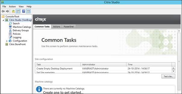
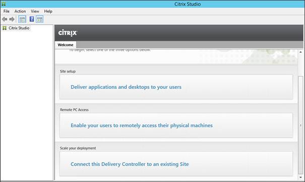
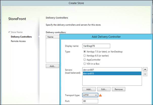
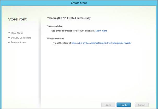
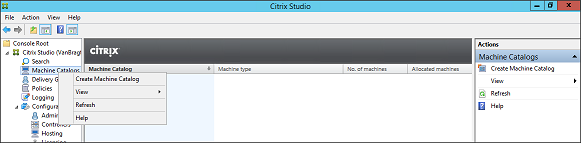
Let’s start with the configuration of the Citrix StoreFront load balancing. Logically we need two Citrix StoreFront servers for this set-up and a free IP address in the range of the NetScaler VPX Express appliances. I prefer to have the Citrix StoreFront servers running into Server Group to guarantee that the StoreFront configuration is identical.

Figure 1: Citrix StoreFront Server Group
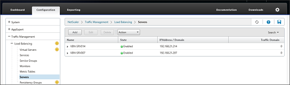
Within the NetScaler GUI the first step is to go the Configuration Tab, followed by Traffic Management – Load Balancing – Servers.

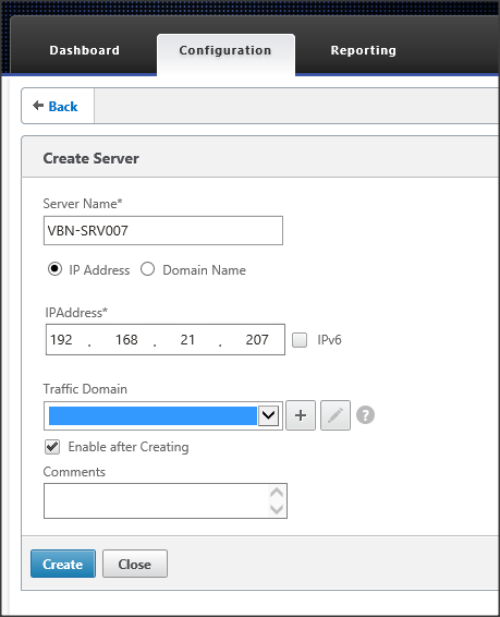
In this part we need to specify the actual servers hosting the StoreFront role. In my case these are the SRV-VBN007 and SRV-VBN014. Add each node by specifying the servername and the IP address.
When both servers are added they will be shown in the servers overview.

The next step is to create Monitors for these StoreFront servers. NetScaler has specific StoreFront servers monitoring included that actually check if the Storefront is available. Therefore we need to go to Traffic – Management – Load Balancing – Monitors within the Configuration tab. Again choose the Add button.
First you need to enter a name for the monitor. You can use whatever you want (but keep the name logical). Select type as StoreFront, so the specific StoreFront monitor functionality will be applied. Addtionally you can specify the Destination IP at the standard parameters. However you are not required to do that, as if this value is empty the IP address of the server will be used. If you enter a destination IP address you need to create a monitor for each StoreFront server, when leaving this value empty one monitor can be applied to more servers.

Figure 6: Create Monitor
At the special parameters tab the Store Name of the StoreFront configuration needs to be entered. Also ensure that the StoreFront Account Service box is checked.
After we created the monitor we are ready for creating the service. This can be found at Traffic Management – Load Balancing – Services again within the Configuration tab. Choose the Add button once again.

Figure 8: Load Balancing Services
First we need to provide a service name. Again you can type in what you like, but again use a logical naming convention. I’m using SFSRV_<> as an example. As we already created the servers earlier, we now can select Existing Server and choose the corresponding server. Select the protocol and port number. In my example I don’t have certificates, so I’m using port 80 and HTTP. However for production environment I advise to use SSL with port 443.
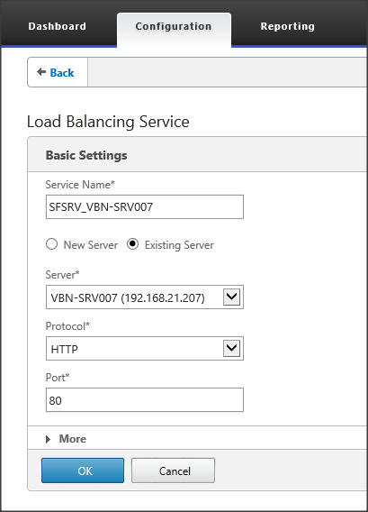
Figure 9: Load Balancing Service set-up
The service will be created and shown in the next window. By default the standard HTTP monitor is applied, but we would like to add our created StoreFront monitor. Scroll down to Monitors and choose the > symbol behind 1 Service to Load Balancing Monitor Binding.
The Service Load Balancing Monitor Binding window opens. To add our monitor, we need to choose the option Add Binding.
Again we already created the Monitor so choose the > symbol again and pick the created service out of the list. Leave the other values in their default state.
The binding is replaced by the just selected monitor. Close this window via the Close button (it can take some time for the Current State changes). Choose Done to close the service window as well.
Repeat these steps for the second StoreFront Server. At the end you have two services defined, where the state should be Up (based on the StoreFront Monitor we have bind to the service).
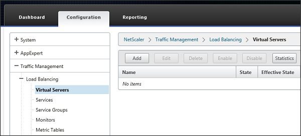
The last step within the NetScaler management console is to create the actual virtual server, which will be the entry point for the end-user to access the StoreFront infrastructure. Go to Traffic Management – Load Balancing – Virtual Servers (under Configuration) and use the Add button again.
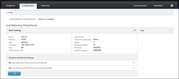
Provide a name for the virtual server. Again you can provide whatever you want. Specify the protocol the virtual server should respond to. In my case I will use port 80, when using certificated use SSL. Last enter the IP address for this virtual server.
Free Fault Tolerant Load Balancing using Citrix NetScaler Express (Part 2) - Citrix StoreFront/Web Interface and XML Broker
by Wilco van Bragt [Published on 24 Sept. 2015 / Last Updated on 24 Sept. 2015]
In this second part I describe how to load balance the Citrix StoreFront/Web Interface and Citrix XML Desktop Delivery Controller (XML) services. - Free Fault Tolerant Load Balancing using Citrix NetScaler Express (Part 1)
- Free Fault Tolerant Load Balancing using Citrix NetScaler Express (Part 3) - Microsoft RD Web Access and RD Connection Broker
Introduction
In the first article of this article series I described the installation and configuration of a high available/fault tolerance free NetScaler VPX Express set-up. This set-up can be used to load balance all kind of services for free.Advertisement
Citrix StoreFront/Web Interface
Let’s start with the configuration of the Citrix StoreFront load balancing. Logically we need two Citrix StoreFront servers for this set-up and a free IP address in the range of the NetScaler VPX Express appliances. I prefer to have the Citrix StoreFront servers running into Server Group to guarantee that the StoreFront configuration is identical.
Figure 1: Citrix StoreFront Server Group
Within the NetScaler GUI the first step is to go the Configuration Tab, followed by Traffic Management – Load Balancing – Servers.

Figure 2: NetScaler Load Balancing
In this part we need to specify the actual servers hosting the StoreFront role. In my case these are the SRV-VBN007 and SRV-VBN014. Add each node by specifying the servername and the IP address.

Figure 3: Create Server Node
When both servers are added they will be shown in the servers overview.

Figure 4: StoreFront Servers added
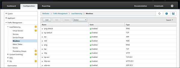
The next step is to create Monitors for these StoreFront servers. NetScaler has specific StoreFront servers monitoring included that actually check if the Storefront is available. Therefore we need to go to Traffic – Management – Load Balancing – Monitors within the Configuration tab. Again choose the Add button.

Figure 5: Configure Monitors
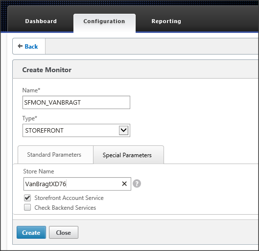
First you need to enter a name for the monitor. You can use whatever you want (but keep the name logical). Select type as StoreFront, so the specific StoreFront monitor functionality will be applied. Addtionally you can specify the Destination IP at the standard parameters. However you are not required to do that, as if this value is empty the IP address of the server will be used. If you enter a destination IP address you need to create a monitor for each StoreFront server, when leaving this value empty one monitor can be applied to more servers.

Figure 6: Create Monitor
At the special parameters tab the Store Name of the StoreFront configuration needs to be entered. Also ensure that the StoreFront Account Service box is checked.

Figure 7: Configure Store Name of the StoreFront monitor
After we created the monitor we are ready for creating the service. This can be found at Traffic Management – Load Balancing – Services again within the Configuration tab. Choose the Add button once again.

Figure 8: Load Balancing Services
First we need to provide a service name. Again you can type in what you like, but again use a logical naming convention. I’m using SFSRV_<

Figure 9: Load Balancing Service set-up
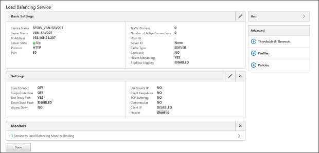
The service will be created and shown in the next window. By default the standard HTTP monitor is applied, but we would like to add our created StoreFront monitor. Scroll down to Monitors and choose the > symbol behind 1 Service to Load Balancing Monitor Binding.

Figure 10: Load Balancing Service created and change monitors
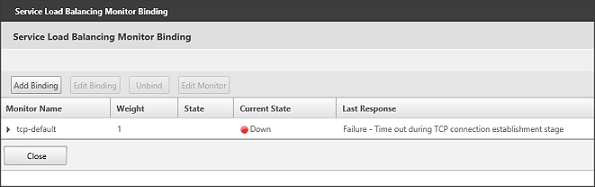
The Service Load Balancing Monitor Binding window opens. To add our monitor, we need to choose the option Add Binding.

Figure 11: Service Load Balancing Monitor Binding
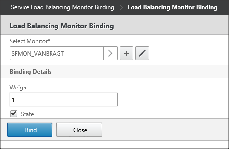
Again we already created the Monitor so choose the > symbol again and pick the created service out of the list. Leave the other values in their default state.

Figure 12: Selecting Load Balancing Monitor Binding
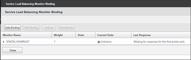
The binding is replaced by the just selected monitor. Close this window via the Close button (it can take some time for the Current State changes). Choose Done to close the service window as well.

Figure 13: Changes Load Balancing Monitor Binding
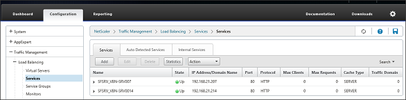
Repeat these steps for the second StoreFront Server. At the end you have two services defined, where the state should be Up (based on the StoreFront Monitor we have bind to the service).

Figure 14: Services created
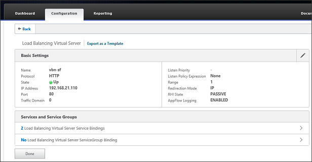
The last step within the NetScaler management console is to create the actual virtual server, which will be the entry point for the end-user to access the StoreFront infrastructure. Go to Traffic Management – Load Balancing – Virtual Servers (under Configuration) and use the Add button again.

Figure 15: Create Virtual Server
Provide a name for the virtual server. Again you can provide whatever you want. Specify the protocol the virtual server should respond to. In my case I will use port 80, when using certificated use SSL. Last enter the IP address for this virtual server.

Figure 16: Add servers
Just as for the StoreFront servers the next step is to set-up the monitor part. Go to Traffic Management – Load Balancing – Monitors. Add a Monitor

The Virtual Server will be created, next we need to assign the created services to this virtual server as resources. Choose the > Symbol behind No Load Balancing Virtual Server Service Binding.
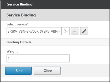
In the Service Binding window choose the > Symbol again to select the services.

Select the corresponding services to add those to the virtual server configuration.
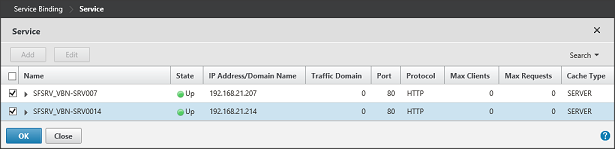
The services are shown in the Select Service field, leave the other values default and choose the Bind button.
Finally we need to specify the Persistence options. These can be found under Advanced in the right pane. For StoreFront we can use several methodologies. One of the best practices is to use COOKIEINSERT, with as back-up persistence SOURCEIP. Leave the other settings as default.

Choose “Done” once more to finalize the configuration. The status will turn green in a short moment and the StoreFront services are now load balancing using a Citrix NetScaler.
The last step is to create a pointer to the virtual server. I created an A record in DNS with the name vbn-sf pointing to the 192.168.21.110 IP address. Now the users can connect via this load balance service to the StoreFront. Don’t forget to save the configuration using the floppy icon.
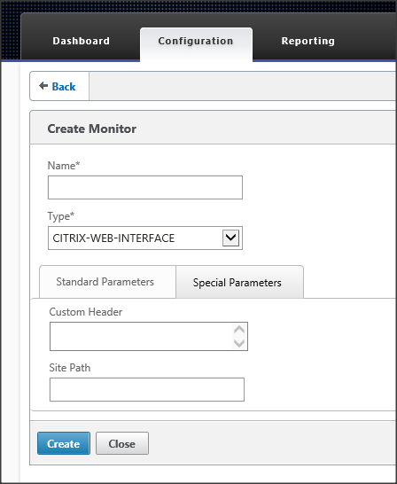
If you are still using a Citrix Web Interface, you can also use the same set-up. The only difference is that at the monitoring configuration you select Citrix-Web-Interface as the type and specify the site path at the special parameters.
Citrix Delivery Controller
Also the Citrix Delivery Controller component can be load balanced using the Citrix NetScaler VPX Express. In all configuration settings within Citrix XenDesktop/XenApp you can configure more Delivery Controllers including a load balancing mechanism. However using the NetScaler Load Balancing has one big advantage, you only need to specify the Delivery Controller actual server names once in the NetScaler. On the other configuration options you specify the Virtual Server name, so when there are changes to the Desktop Delivery Controller you only need to change this in the NetScaler configuration.
The first step is to specify the server which runs the Delivery Controller component within Traffic Management – Load Balancing – Servers as we have also done for the Citrix StoreFront Servers. In this article I’m using the same servers, if you have others check about how to add the server exactly.
The next step is to create the monitor for the Delivery Controller. Again give the monitor the name, specify as type Citrix-XD-DDC. Optionally specify a destination IP, if none specified the IP of the server applied to the monitor will be used. This makes the monitor usable for more services.

Figure 25: DDC Monitor
After the monitor is created, we can start to set-up the services within Traffic Management – Load Balancing – Services. Just as with the StoreFront a service name should be provided. As we already created the server, we can select an existing server. Specify HTTP as the protocol used and fill in the port where the XML Broker traffic is set-to. The default for this is port 80 with XenDesktop/XenApp 7.x, in my case it’s running on port 8080.
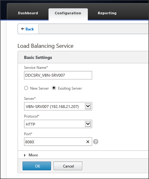
Figure 26: DDC Service
Follow the same procedure to change the monitor of this service to the just created monitor. Press the > symbol and change the monitor binding to the just created monitor. Repeat the creation of the service and change the monitor binding for the second (and more) Desktop Delivery Controllers.

After creating the services for all available Delivery Controllers, we can finalize the set-up by creating the virtual server via Traffic Management – Load Balancing – Virtual Servers by using the Add Button. The same procedure used at creating the StoreFront virtual server is applicable. So first a name, unique IP address, protocol and port number should be specified. Secondly we need to bind the just created services to the virtual server. Third step is to configure the persistence based on SOURCEIP.

Don’t forget to save the configuration using the floppy icon. Now we are ready to use the DDC Load Balancing Virtual Server for example into the StoreFront configuration.

If you are still using a Citrix XenApp 6.x infrastructure the same steps can be used to load balance the XML service. Within the monitor the type should be changed to CITRIX-XML-SERVICE, the other steps and configuration is exactly the same.
Summary
In the first part I described the way to set-up and configure a free High Available Load Balancing infrastructure based on the Citrix NetScaler VPX Express. In this second part we used this infrastructure to set-up a load balanced high available StoreFront and Desktop Delivery Controller infrastructure. In an upcoming article I’m going to describe the steps for load balancing the Microsoft RD Web Access and RD Connection Broker components.
If you would like to read the other parts of this article series please go to: