In this article we will show you how to install VMware Site Recovery Manager 5.8. This step by step guide will help you to understand the design, installation, operation and architecture of setting up VMware Site Recovery Manager (SRM) 5.8.
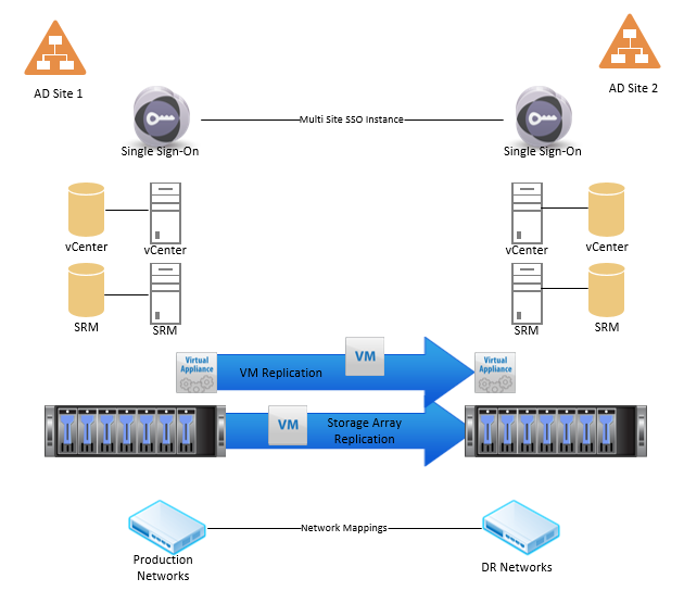
The following components will all need to be configured for a successful SRM implementation:
- 2 or more sites
- 2 or more Single Sign On Servers
- 2 or more vCenter Servers 5.5
- 2 or more SRM Servers
- Storage – Either storage arrays with replication, or 2 or more Virtual Replication Appliances
- Networks
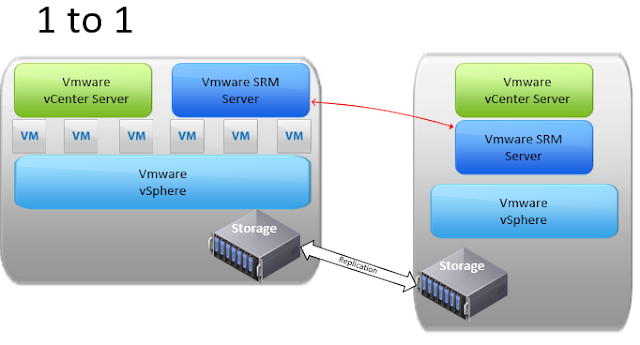
As of VMware Site Recovery Manager 5.8 you can do a traditional Protected to Recovery Site implementation like the one shown below. This can be a unidirectional setup with a warm site ready for a failover to occur, or it can be bi-directional where both sites are in use and a failure at either site could be failed over to the opposite site.
Each site will require their own vCenter Server and SRM Server, as well as a method of replication such as a storage array.
Along with a 1 to 1 setup, SRM 5.8 can manage a many to one failover scenario where multiple sites could fail over to a single site. This would require an SRM instance for each of the protected sites as seen in the diagram below.
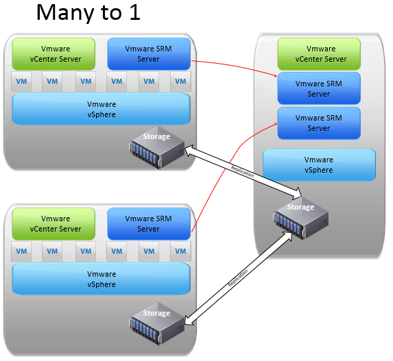
The configuration that is not available at the moment is a single site to multiple failover sites. *as of SRM 5.8
SRM Installation Prerequisites:
Database Prerequisites
Before you are able to install SRM, you’ll need a database to store configuration files. Create a database on your SQL Server to house the configuration information. Note: You’ll need a database server in both the protected site and recovery site; one for each SRM Server.- Pre-create the SQL Database and assign your SRM Service account AT LEAST the ADMINISTER BULK OPERATIONS, CONNECT, AND CREATE TABLE permissions.
- Ensure the SRM database schema has the same name as the database user account.
- The SRM database service account should be the database owner of the SRM database
- The SRM database schema should be the default schema of the SRM database user.
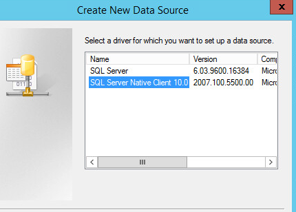
- On your SRM Servers, install the SQL Server native client for your version of SQL Server.
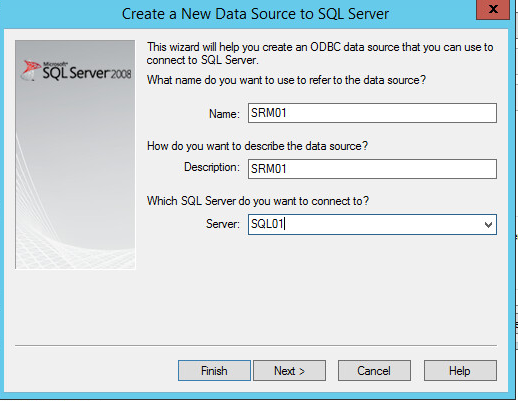
Give it a name, and point the ODBC connection to the server.
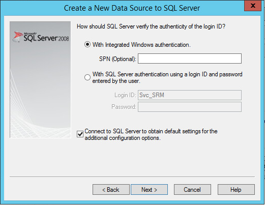
Enter login information.
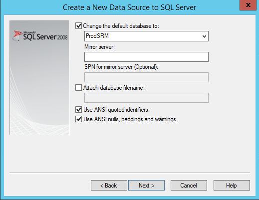
Enter the SRM database
Installer Prerequisites
VMware Site Recovery Manager installation is relatively simple. Grab the installer from http://vmware.com/downloads and run the installer on your SRM Server. There are a couple of notes to be aware of when installing though.- Right click the installer and run as Administrator if you are leaving UAC on. This makes re-installation easier in the future.
- The installation should be done by a user who will be running the SRM Service. The logged in installer by default is the service account that is used.
- The logged in user should have administrative access to the server it’s being installed on.
- Consistent use of SSL Certificates need to be used
- If any vCenter is using custom SSL Certificates then the SRM Services must also use SSL certificates from a Certificate Authority
- If the protected site vCenter uses SSL Certificates then the recovery site vCenter Server should also use SSL certificates from a Certificate Authority
- If you need to use custom SSL certificates from a certificate authority instead of the default VMware certificates, the CN for both SRM servers should be identical
- I recommend reviewing this post from Sam McGeown if you need to use SSL Certificates
Install
Run the installer as an administrator. Click Next on the welcome screen.
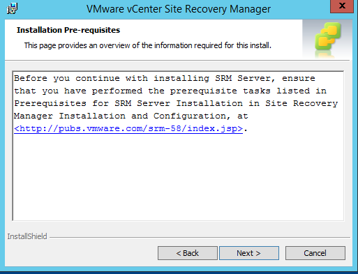
You can view additional prerequisite tasks from the next screen. I’ve covered many of them already in this post.
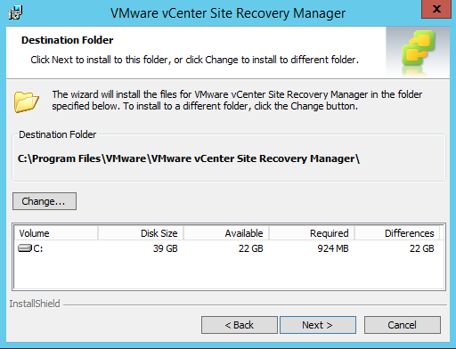
Choose the location for the install files.
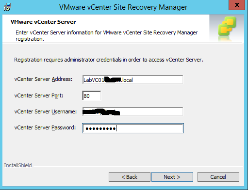
Enter the location of the vCenter server associated with the SRM Server, as well as some credentials to register the service with vCenter.
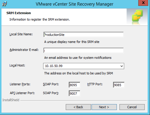
Give the site a name and enter an email address and select the Host IP Address and ports to be used.
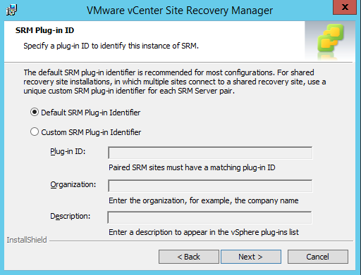
If you’re using the same SRM Server for multiple sites, select the Custom SRM Option and enter the information, otherwise just use the default if it’s a 1 to 1 relationship with another SRM Server.
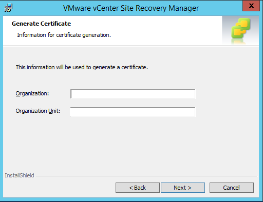
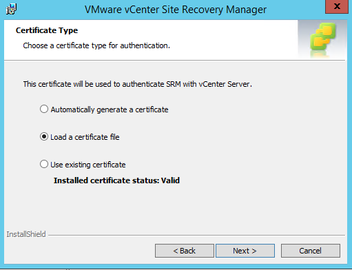
If you’re using the default SSL Certificates then click the “Automatically generate a certificate and then enter some certificate information to generate a cert.
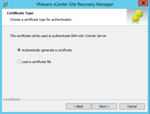
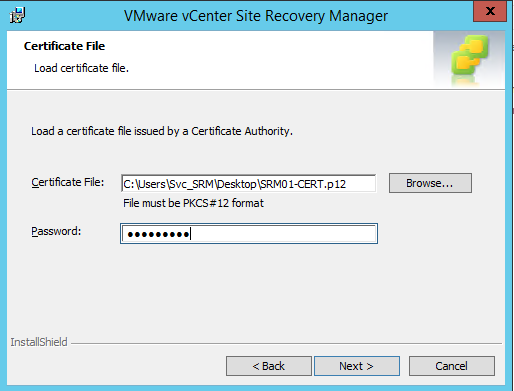
If you’re using custom SSL Certificates, then you’ll load your SSL Certificate during this phase.
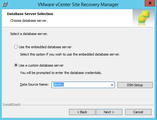
Next, select your Data Source that you created prior to the installation. (If you forgot to do this, there is a button to do it during setup)
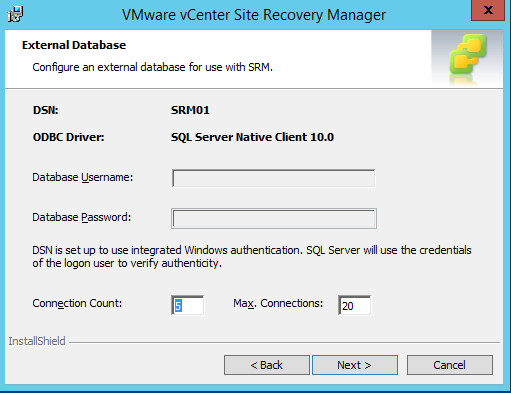
Select the connection counts for the database.
Enter the password for the service account for the Site Recovery Manager Server. The user will be the logged in user.

Once all the information has been entered, click the Install button.
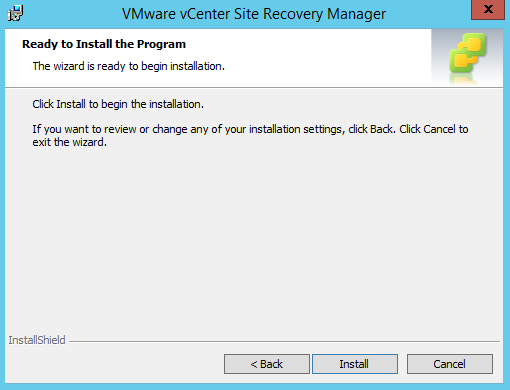
Watch as the installer progresses.

There are quite a few things that need to be done before the install process happens, but it will make your life simpler to have these done beforehand. Now that you’ve installed SRM on one of your sites, repeat the process for the second site.
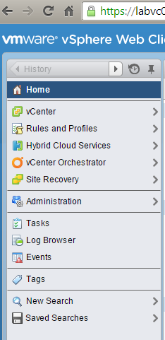
If you notice, now that SRM has been installed, the vSphere Web Client now has a Site Recovery menu in it. (If it doesn’t, log out and back in)
From here, we can go into the new SRM menus.
Site Pairing
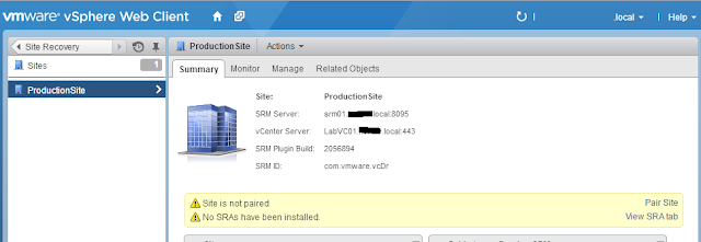
Once you’ve gotten to the SRM Menus, we’ll want to click on Sites to configure our Sites.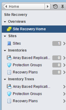
Note: If you see the error below, this means that you’ve got an SSL Certificate mismatch between the SRM Server and the vCenter server. If you use custom SSL certificates for vCenter, you must use them on your SRM Installation as well.
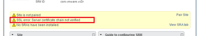
Assuming all your installations have gone well, you’ll see a screen like the one below. Click the “Pair Site” link to get started with the site configuration.
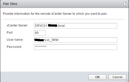
Enter the vCenter information for the remote vCenter. This will pair your site with the opposite site and create a relationship between them.
If you are using the default VMware certificates, you’ll need some login information entered.
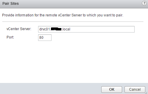
If you are using custom SSL certificates from a certificate Authority, login information is not needed.
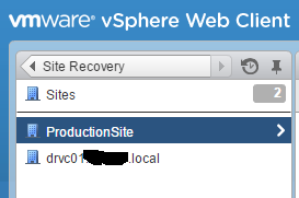
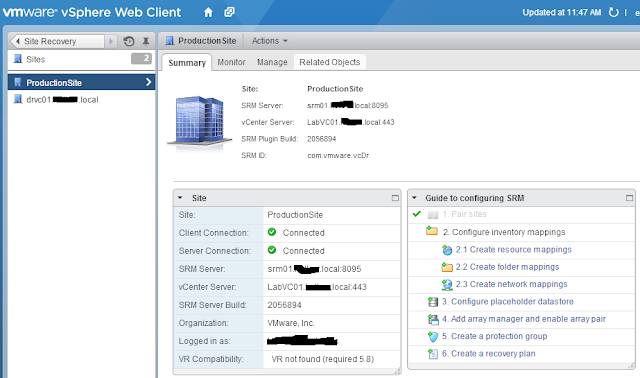
Once Site Pairing is done, you’ll see two sites in the SRM Sites menu
Resource Mapping
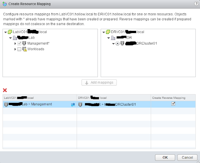
Now that the sites are paired, we can setup mappings for the relationships between the two sites. This includes Resource Pools, Folders, and Networks.Open up one of your sites and you’ll see a helpful “Guide to Configuring SRM” menu. We’ll go right down the list by selecting the Create resource mappings.
Select a relationship between the protected network and the recovery network. Once you’ve created your relationship click the Add Mappings button to add it to your mapping list. When done, you can click the check box to create the same mapping in the reverse direction for fail back operations. You can select a many to one relationship here, but if you do, you won’t be able to select the Reverse Mapping option. Click OK.
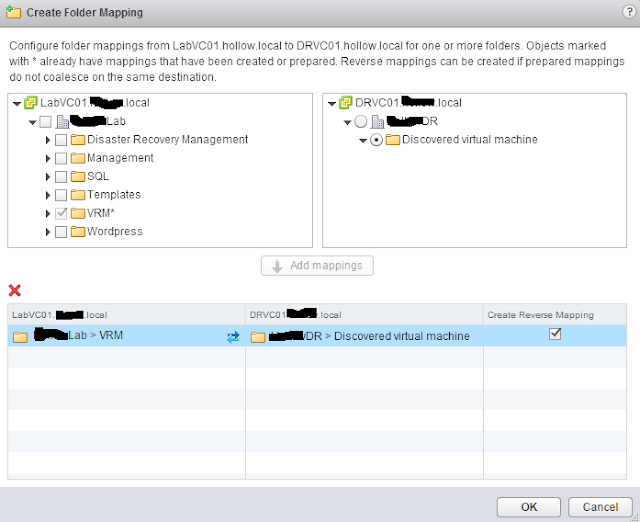
Now we can click the “Create folder mappings” link in the guide to create a relationship for the virtual machine folders. Repeat the process we did for resources, only this time for virtual machine folders. The same rules apply for many to one relationships. Click OK.
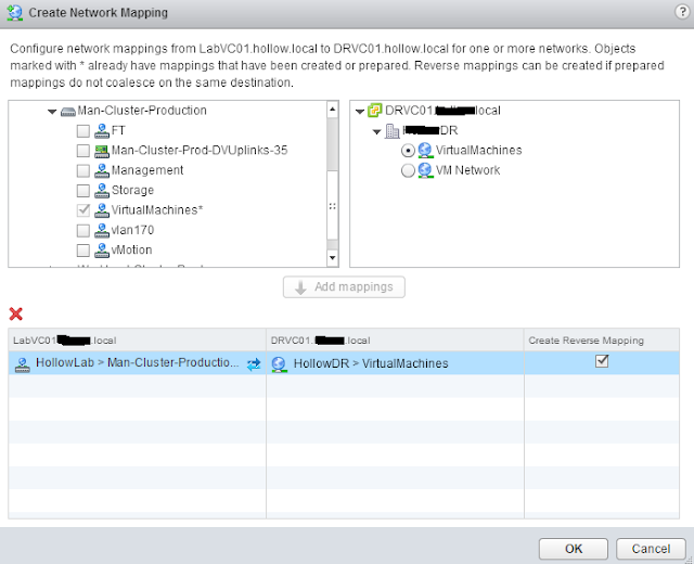
The next mapping we’ll need to do is for networking. Map a network in the protected site to a recovery network. Don’t worry about IP Addressing yet, we can customize this later, but you’ll need to know what network the virtual machines will map to during a failover.
Placeholder Datastores
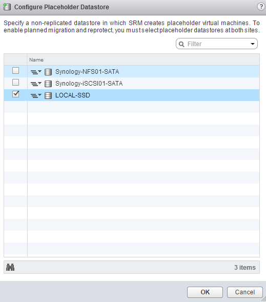
The next section of the “SRM Configuration Guide” is to create placeholder datastores. These datastores hold the configuration information for the virtual machines that are to be failed over. Think of this as a .vmx file that is registered with vCenter without disks. During a failover this virtual machine becomes active and the replicated virtual disks are attached to it. This datastore should not be a replicated datastore, and does not need to be very large to store these files.Configure the placeholder datastore. Select one or more datastores to house the virtual machine files. Click OK.
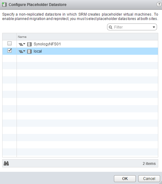
Once done, you’ll want to go to the other site and configure a datastore for it as well. This is so the mappings are already done if you fail over and want to fail back.
We’ve now installed SRM and configured the sites. We can now start looking at setting up replication and protection groups in the next step.
If you plan to use Array Based Replication for your SRM implementation, you’ll need to install and configure your Storage Replication Adapter on your SRM Servers. The SRA is used for SRM to communicate with the array to do things like snapshots, and mounting of datastores.
Pair the Arrays
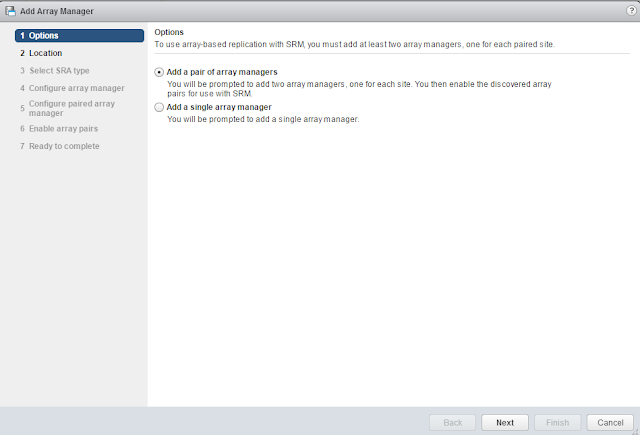
Once your SRAs have been installed in both your sites and you’ve gotten the arrays replicating, you’ll want to pair the arrays in SRM so that they can be used for protection Groups. Open the “Array Based Replication” tab in the “Site Recovery” menu of the web client. Click the Add button.Here, we’ll want to add a pair of array managers (one for each site).
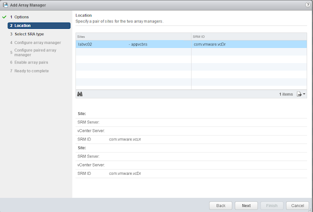
Select the sites that you’ll be workign with.
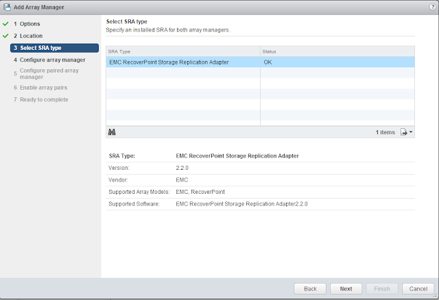
Choose the SRA type. If you only have one SRA installed, only one option should be available. In this case, we’re using EMC RecoverPoint.
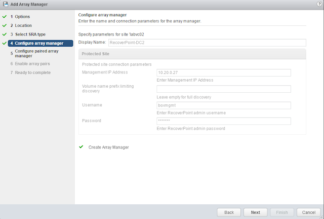
Now, we need to configure the manager with the IP Addresses, and names as well as an account that has enough privileges to create snapshots, as well as mount and unmount LUNs.
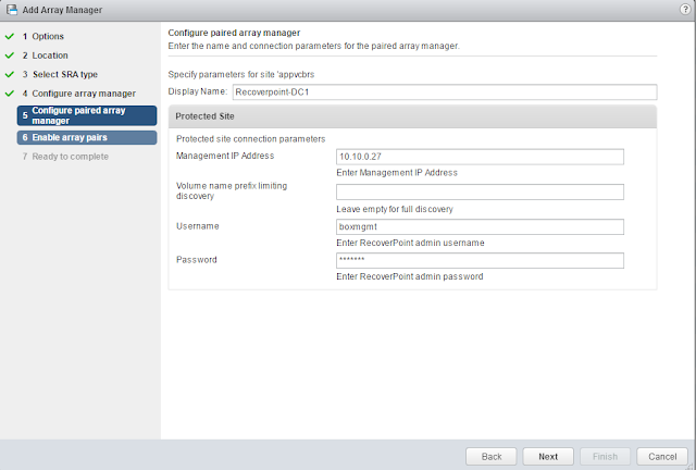
Now we’ll configure the opposite site’s array manager as well. Same rules apply.
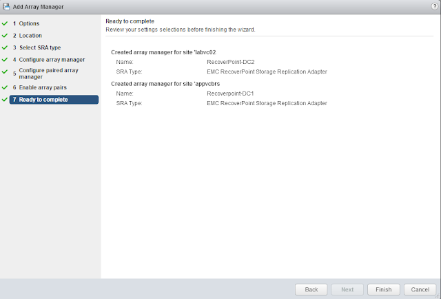
Once we’ve configured the array managers we can enable them which will make them a pair that replicate to each other.
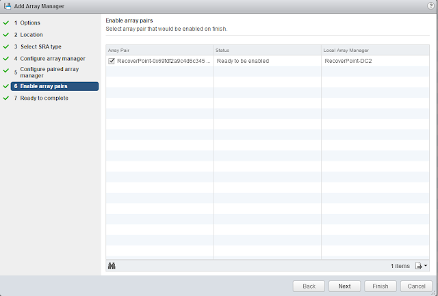
Finish the wizard.
Protection Groups for Arrays
When you create a protection group for virtual machines being replicated by array based replication, you will give it a name as usual, and a site pair.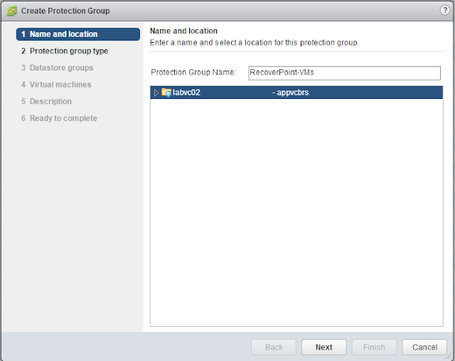
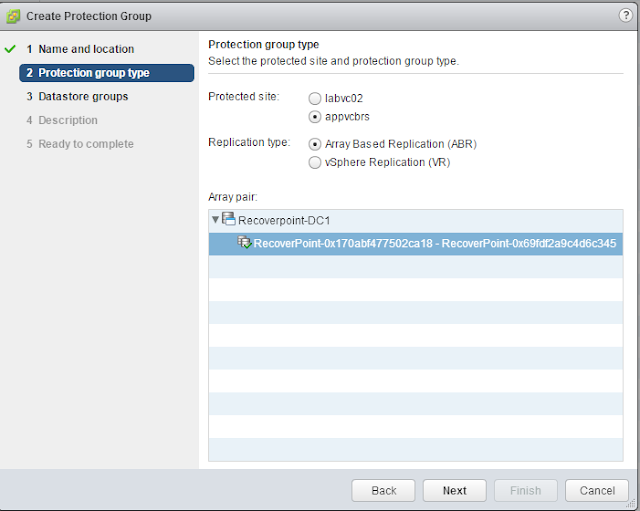
Choose the Protected site and the that it’s an Array Based Pair. Select the pair.
Select the datastores that contain the virtual machines. All of the virtual machines on this array pair will be protected.
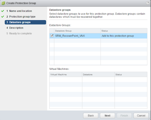
Array based replication does not take much additional effort for VMware Site Recovery Manager, but may take some additional planning to make sure your protection groups are in the right datastores. Remember that all VMs in a datastore will be failed over together.
SRM Sites and resource mappings are all done. It’s time to create some Protection Groups for our new VMware Site Recovery Manager deployment.
A protection group is a collection of virtual machines that should be failed over together. For instance, you may want all of your Microsoft Exchange servers to fail over together, or you may want a Web, App, Database Tier to all failover at the same time. It is also possible that your main goal for SRM is to protect you in the event of a catastrophic loss of your datacenter and you’re concerned with every VM. It still a good idea to create multiple protection groups so that you can fail over certain apps in the event of an unforeseen issue.
Think about it, if your mail servers crashed but the rest of your datacenter is fine, would it make sense to just fail over the mail servers, or the entire datacenter? Just failing over the mail servers would make sense if they are in their own protection group.
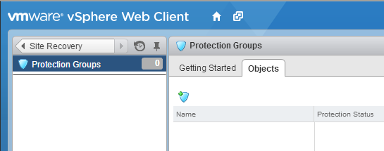
If we look at the protection groups menu of Site Recovery we’ll want to click the shield icon with the “+” sign on it.
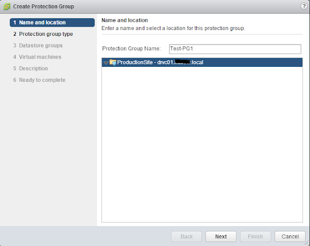
Give the new protection group a name. Of course give it a descriptive name. A name like “Protection Group 1” doesn’t work very well when you have lots of protection groups. Name it something easy to identify. Back to my examples, I’ve named my protection group, “Test-PG1”. Yep, I’m a hypocrite. Click Next.
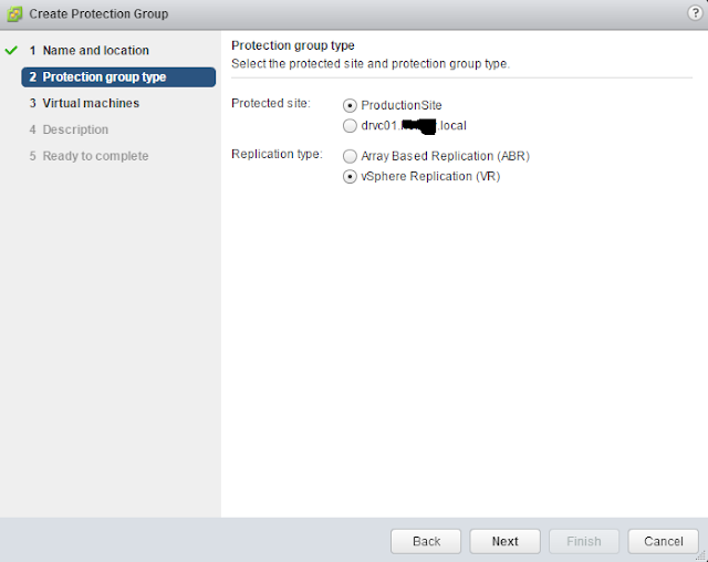
Select the Protected Site and a replication strategy. In my lab, I’ve setup vSphere Replication so I’ve chosen that as my replication type. Click Next.
NOTE If you are using Array Based Replication, make sure that you don’t have multiple protection groups on the same LUN or consistency group. The entire LUN would be taken offline during a failover of a protection group, so having some VMs that aren’t supposed to failover on the same LUN could cause you an issue.
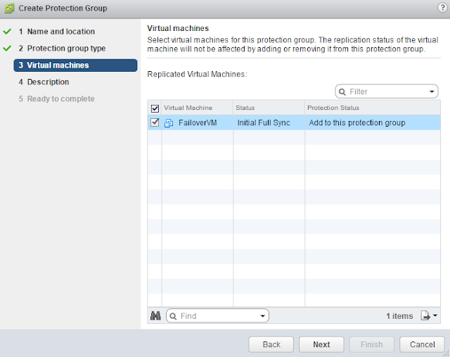
Select the Virtual Machines to fail over. The populated list will only show virtual machines that are being replicated. As you can see from the screenshot below, the VM named “FailoverVM” is available for protection even though I have many VMs in my vCenter. “FailoverVM” is the only one that is being replicated. Click Next.
NOTE: If you are using Array Based Replication, you will be selecting a datastore vs individual virtual machines. The same rule about replication holds true, however. Only replicated datastores should show up in this menu.
Give the Protection group a good description. Click Next.
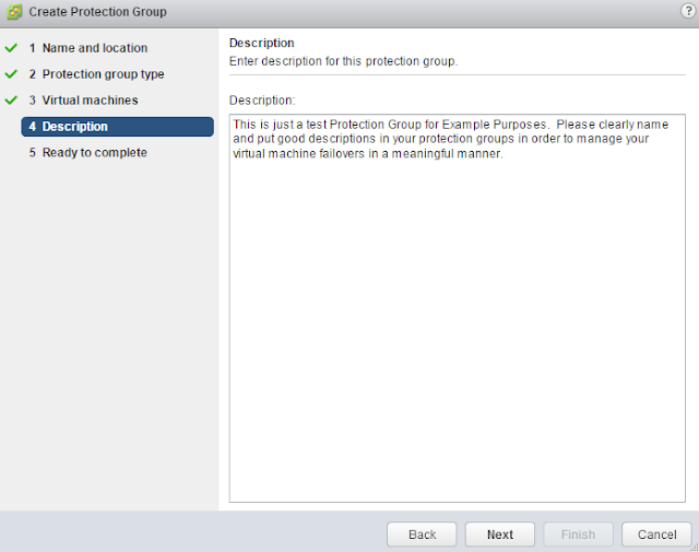
Review the Protection Group settings and click Finish.

Protection groups are simple to setup in Site Recovery Manager, but could take a considerable amount of planning to make sure VMs are in the correct LUNs. The planning of your entire disaster recovery plan should be designed with this in mind.
A recovery plan is the orchestration piece of Site Recovery Manager and likely the main reason for purchasing the product. All of the setup that’s been done prior to creating the recovery plans is necessary but the recovery plan is where magic happens.
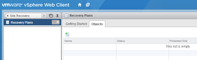
When we go to the Recovery Plans menu in Site Recovery, we’ll see the option to click the notepad with the “+” sign on it to create a new recovery plan.
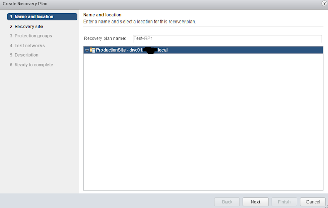
Give the recovery plan a descriptive name. Remember that you can create a recovery plan for individual protection groups, or multiple protection groups. This allows you the opportunity to create individual recovery plans for things like “Mail Services”, “Database Services”, “DMZ”, “File Servers” and then create a catch all named “Full Recovery” that includes all of the protection groups. This allows for flexibility with whatever outage you’re planning for.
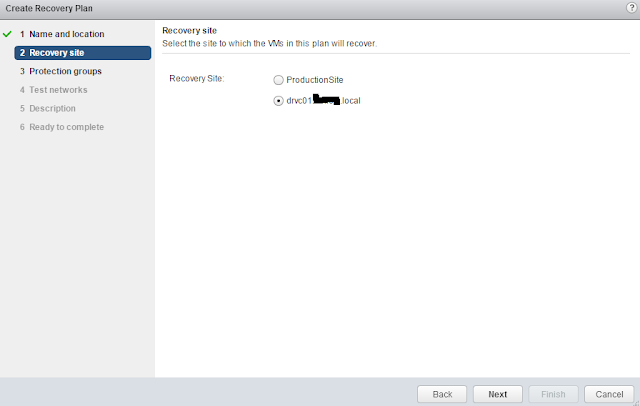
Choose which site is the recovery site and click Next.
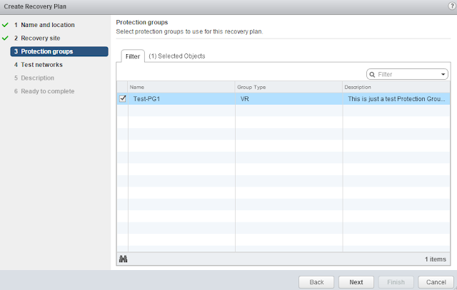
Select the Protection Groups that are part of this recovery plan. In the example below, there is only one protection group, but you could select many if they are available. Click Next.
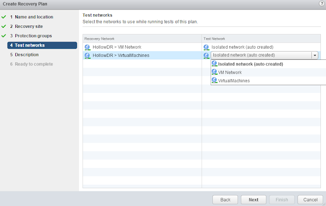
Select the test networks. We’ve already created mapping for networking that should show handle what happens when a virtual machine fails over to the recovery site, but we need to configure what happens when we run a “TEST” recovery. During a failover test, we may not want the VM to be on the same network as our production servers. Leaving the “Isolated network (auto created) as the test network, allows us to create a virtual switch with no uplinks in order to ensure that the virtual machines won’t be accessible via the network during a test.
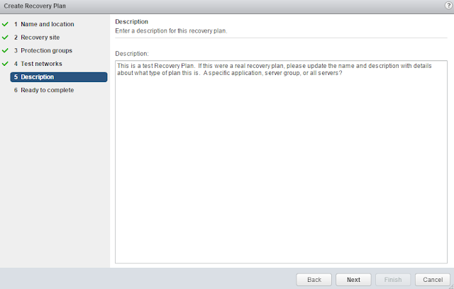
Give the recovery plan a description and click Next.
Review the settings and Click Finish.
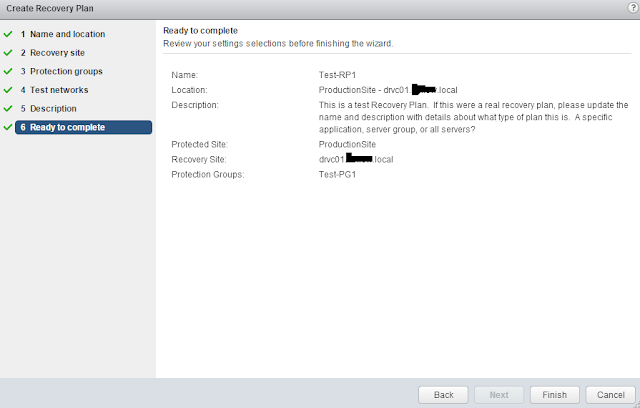
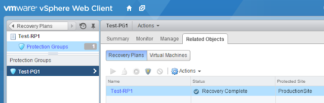
Once done, we can see that a Recovery Plan is available and we can run a test or a failover.
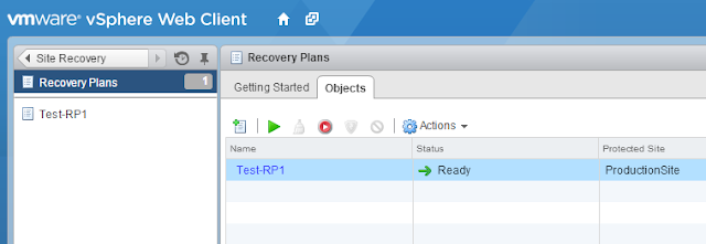
This is the basic layout of a recovery plan. Most disaster recovery plans require a lot more customization than just powering on a virtual machine at another location. In upcoming steps we’ll review many more options that are available when setting up a recovery plan such as IP customization, power-on priorities and scripting.
Some companies have built out their disaster recovery site with a stretched layer 2 network or even a disjoint layer 2 network that shares the same IP addresses with their production sites. This is great because VMs don’t need to change IP Addresses if there is a failover event. This post goes over what options we have if you need to change IP Addresses during your failover.
Network mappings
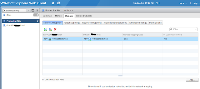
SRM 5.8 has a wonderful new way to manage IP Addresses between datacenters. Prior to SRM 5.8 each VM needed to be manually updated with a new IP Address or done in bulk with a CSV template (show later in this post) if you had to re-IP your VMs. Now with SRM 5.8 we can do a network mapping to make our lives much easier. This is one of the best new features of SRM 5.8 in my opinion.Go to your sites in “Site Recovery” and click the Manage tab. Here, you’ll see our network mappings again. Click the networks that you’ve mapped previously and then you can click the “Add…” button to create some IP Customization Rules.
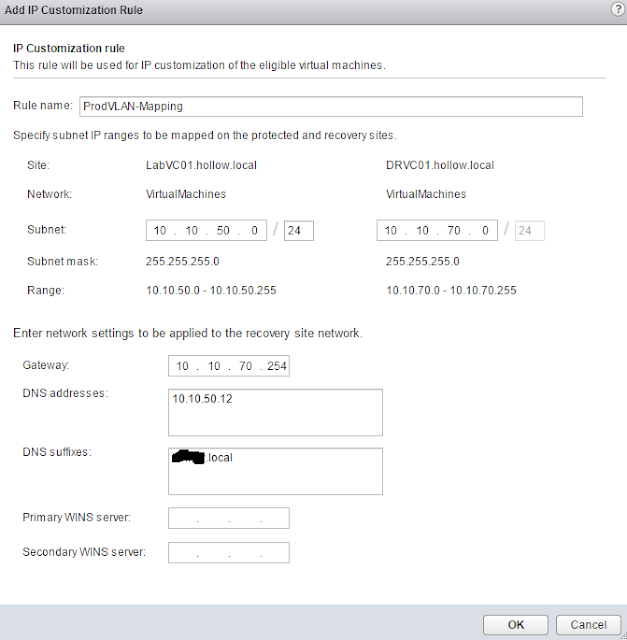
When the “Add IP Customization Rule” screen comes up, you can see that we can now map the networks to one another and the virtual machine will keep the host bits the same between networks. For example, if you have a VM on the 10.10.50.0/24 network with an IP Address of 10.10.50.100, and it needs to failover to the 10.10.70.0/24 network, it will keep it’s hosts bits the same, and just change the network, making it 10.10.70.100 at the DR site
Obviously, there are a few other things that you’ll need to modify such as DNS Servers, suffixes and of course the default gateway.
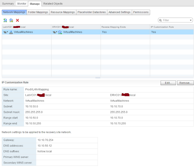
Once you’ve created your IP Customization Rules, you can see them listed below the network mappings for your virtual machines.
Manual IP Customization
If the subnet mapping spelled out above doesn’t work, you can manually customize an IP Address of each VM. Go into your recovery plans and find the virtual machine to customize. Right click and choose “Configure Recovery…”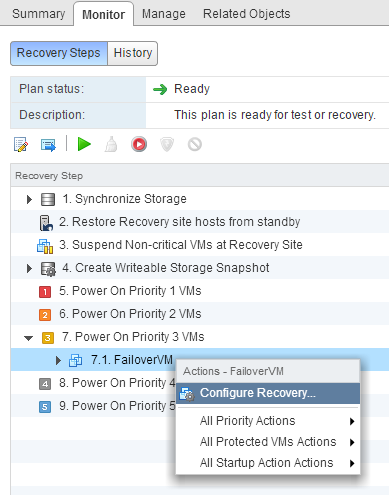
Click the IP Customization Tab. Here you’ll see that you can add IP Addresses for both sites. Be sure to enter IP information in for both sites. If you failover to the recovery site and didn’t set the protected site IP Addresses, you’ll have some IP issues when you try to fail back.
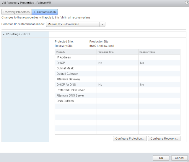
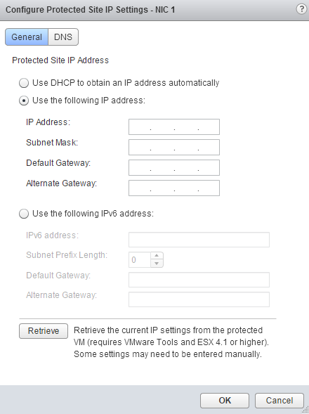
Click either the “Configure Protection…” or “Configure Recovery…” and then you can enter your IP information. Again, be sure to do both sites.
BULK IP Customizer
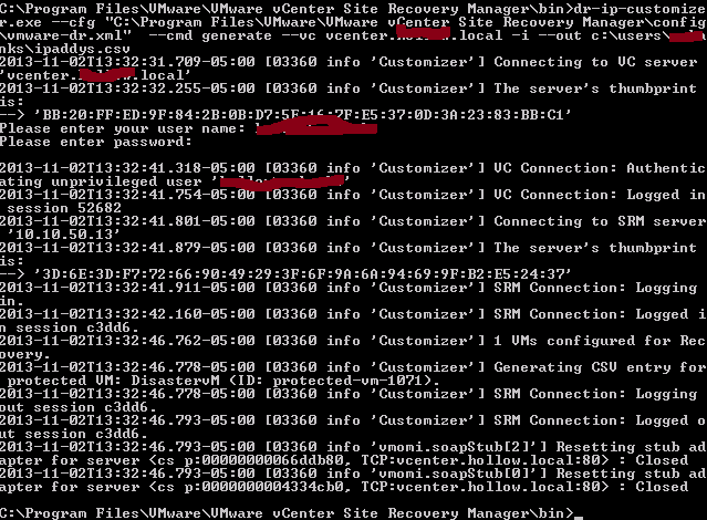
Many times it’s not practical to modify the IP addresses of every individual VM as they are configured. Luckily VMware has provided a way to bulk upload IP addresses.From an SRM server, open a command prompt and change the working directory to: c:Program FilesVMwareVMware vCenter Site Recovery Manager bin
NOTE: Path may be different depending on your install location.
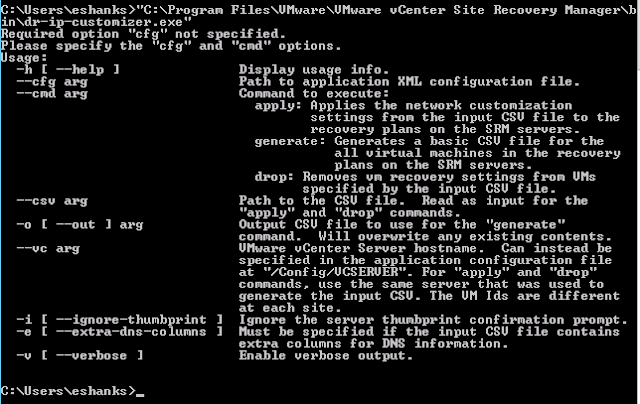
Generate a .CSV file to edit your IP Addresses by running dr-ip-customizer.exe with the –cfg, –cmd –vc -i –out switches.
–cfg should be the location of the vmware-dr.xml file. –cmd should be “Generate”, –vc lists the vCenter server, and –out lists the location to generate the .csv file.
Example: dr-ip-customizer.exe –cfg “C:Program filesVMwareVMware vCenter Site Recovery ManagerConfigvmware-dr.xml” –cmd generate –vc FQDNofvCenter -i –out c:ipaddys.csv
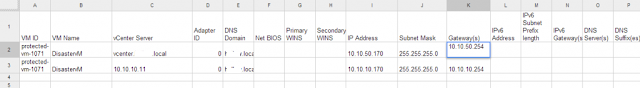
Open the .csv file and fill out the information. Notice that there are two entries for the VM. This is because there are two vCenters and in order to do protection and fail back we need the IP Addresses for both sides.
Once the IP Address information is entered, run the customizer again with the –cmd “Apply” and –CSV file location.
Example: dr-ip-customizer.exe –cfg “C:Program filesVMwareVMware vCenter Site Recovery ManagerConfigvmware-dr.xml” –cmd apply –vc FQDNofvCenter -i –csv c:ipaddys.csv

IP changes during a SRM failover are a necessity for many companies and SRM 5.8 has both made this process easier as well as giving plenty of options depending on your needs. We can now use network mapping, manual IP customization or bulk IP customization to accomplish our objectives.
It’s time to failover your datacenter to your disaster recovery site. Well, maybe you’re just migrating your datacenter to a new one, but this is always a bit of a tense situation.
Go to the Recovery Plan and click the monitor tab. Click the “BIG RED BUTTON” (yeah, it’s not that big, but it has big consequences).

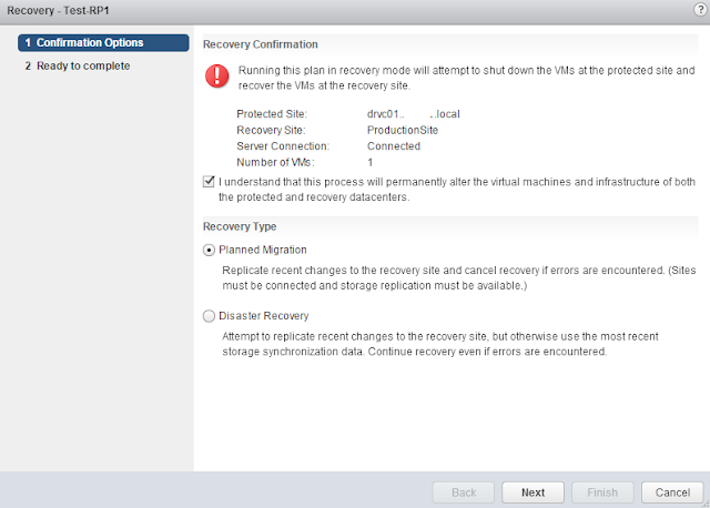
Before the failover actually happens, you’ll be given a warning and you actually have to click a check box stating that you understand the consequences of performing this operation. After that you’ll be given the opportunity to do a Planned Migration which will try to replicate the most recent changes and will stop if an error is encountered, or a Disaster Recovery migration which will just failover anything it can and as fast as it can. Pick your recovery type and click Next.
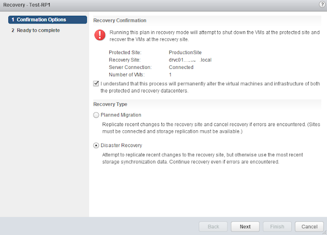
Review the process that is about to happen and click Finish.

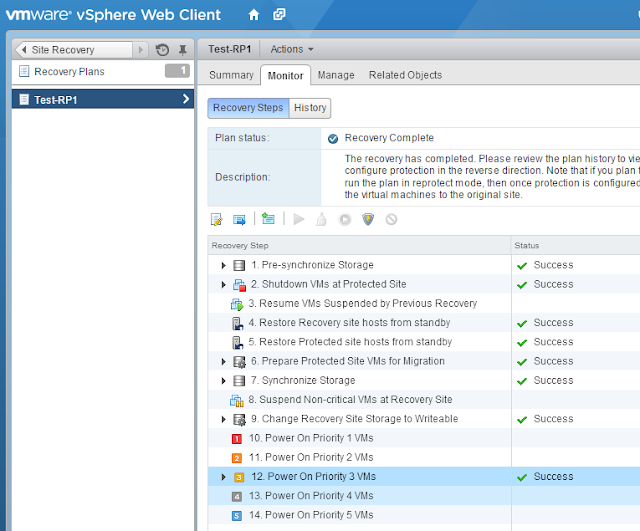
While the recovery is running, you’ll be able to monitor the process on the recovery steps screen. Notice that this is slightly different from a test recovery in a few places, such as not creating a writable snapshot but rather making the existing storage writable in the new datacenter. Hopefully everything is working well for you after the failover.
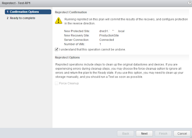
Now it’s time to go back to our original datacenter. Click the “Re-Protect” button which looks like a shield with a lightning bolt on it. This Re-Protect will reverse the direction of the replication and setup a failover in the opposite direction. You can consider the DR site to be the protected site and the original production site to be the recovery site, until you fail back.
When you run the Re-Protect, you’ll need to once again confirm that you understand the ramifications of this operation.
Now that everything is reversed, you can run another failover, but this time a “Planned Migration” is probably more reasonable since you’re likely planning to do a failback and it’s not a second disaster, this time at your disaster recovery site.
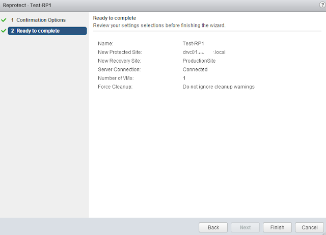
Review the failover and click Finish. When the failover is done, be sure to Re-Protect it again to get your disaster recovery site back in working order.
Failovers can be stressful but thankfully we’ve tested all of our plans before, so that should take some of the pressure off.
Run a Test
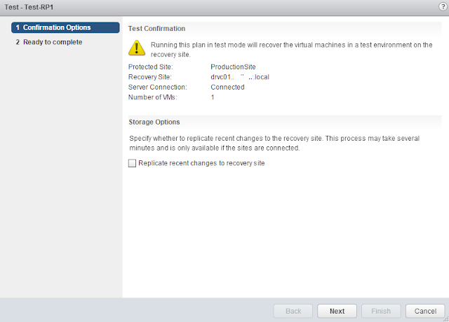
Open up one of your recovery plans and click the monitor tab. Here you’ll have several buttons to choose from as well as seeing the list of recovery steps. To run a “Test” recovery click the green arrow button.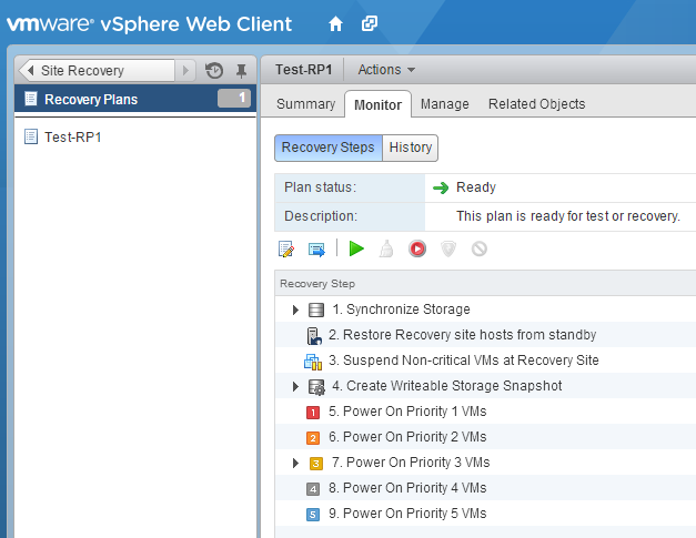
Once you’ve begun the test process, you’ll be prompted about whether or not you want to run one additional replication to the DR site. You’ll have to decide what you’re testing here. If it’s a disaster test, then you probably don’t want to run an additional replication because you can’t hold off your disaster until you replicate one more time. If you’re test is for a planned datacenter migration then maybe this is applicable to you.
Review your test settings and click Finish. Once the test starts, it will create a snapshot of the storage at the DR site so that replication can continue in the background while the test is run. It may also create some new virtual switches if you’re running an isolated test.

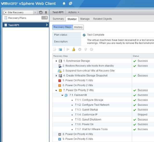
During the test, you’ll be able to monitor the recovery plan every step of the way. If you encounter a failure, you’ll know what step failed and you’ll be able to fix it and try again. Assuming everything goes as planed, you’ll get a “Test Complete” message with a check mark. Once the test is complete you can login to some of your virtual machines to ensure things are how you expect them to be after a failover. When you’re ready to finish the test, click the broom icon in the recovery plan menu.
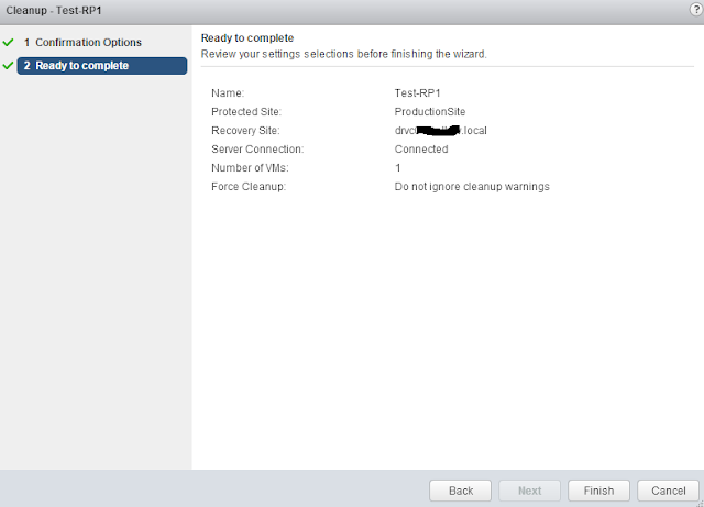
When you click the cleanup button, you’ll get a confirmation much like you did when you ran the test. Click Next.
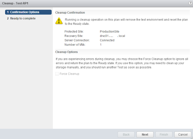
Review the cleanup settings and click Finish. When you click Finish, the snapshots created at the recovery site will be deleted, any isolated virtual switches used for the test will be destroyed, and the placeholder VMs will be ready for another failover.
We don’t have to wait for a long test window to try our DR plan any longer. We can test during the middle of the day, test once a month, week, day or hour if you really wanted to. Now we have some semblance of certainty that our DR plan will work successfully if the time arises.